
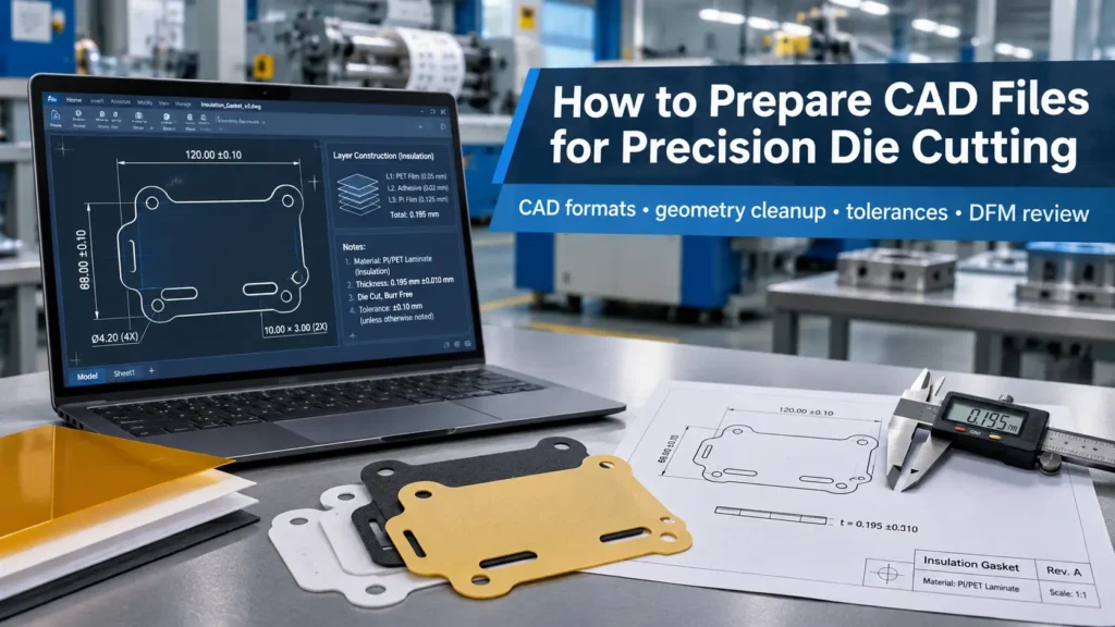
How to Prepare CAD Files for Precision Die Cutting?
Table of Contents
An EV battery manufacturer sends a DXF drawing of a custom insulation pad to a precision die-cutting supplier. The outer profile appears correct, and the mounting holes are positioned as intended. However, the supplier discovers that the drawing units are unclear, several cutting paths overlap, the adhesive and release-liner construction are missing, and some internal features have no defined cutting requirements. The geometry may look complete, but the information needed for manufacturing is not. These gaps can trigger engineering clarification, affect quotation assumptions, and complicate prototype approval.
To prepare CAD files for precision die cutting, engineers should confirm the supplier’s accepted file formats, establish consistent drawing units and 1:1 geometry, remove duplicate or unintended entities, and clearly identify all cutting contours. They should distinguish through-cut from kiss-cut features, specify material and laminate construction, define critical dimensions and tolerances, and include manufacturing notes, inspection requirements, and revision information. Before requesting a quotation, engineers should validate the exported CAD data against an approved PDF engineering drawing and request a supplier DFM review.
A manufacturing-ready CAD package communicates more than the shape of a component. It defines the intended finished-part geometry, material construction, cutting requirements, dimensional expectations, and acceptance criteria.
The distinction matters particularly for custom insulation components, where a thin polymer film, compressible silicone foam, and fiber-reinforced insulation composite may respond differently to the same nominal geometry.
Which CAD File Formats Are Best for Precision Die Cutting?
DXF and DWG are commonly used for exchanging two-dimensional CAD geometry, but neither format is universally preferred by every precision die-cutting supplier. DXF is often a practical exchange format for cutting profiles, while DWG can preserve a broader native drawing environment. PDF provides an important reference for approved dimensions and manufacturing specifications. STEP files add three-dimensional assembly context, and AI or SVG may be useful for certain vector-based workflows if the supplier confirms compatibility.
The correct format depends on the supplier’s CAD/CAM software, supported file versions, geometry requirements, and quotation workflow.
CAD File Format Comparison
| File Format | Typical Role | Main Advantage | Limitation / Supplier Check |
| DXF | 2D cutting geometry | Widely used for exchanging vector profiles | Confirm version, units, entity types, and CAM compatibility |
| DWG | Native CAD drawing | Preserves drawing structure and editable entities | Confirm software and version compatibility |
| Approved engineering drawing | Communicates dimensions, notes, tolerances, and revisions | Vector PDF geometry is not automatically machine-ready | |
| STEP / STP | 3D model and assembly context | Communicates spatial relationships and component interfaces | Usually requires extraction of the relevant 2D profile |
| AI | Vector artwork and paths | Useful for certain vector-based design workflows | Confirm path interpretation, scale, and export requirements |
| SVG | Scalable vector geometry | Supports editable paths and vector exchange | Confirm units, transformations, and curve compatibility |
DXF vs. DWG: Which Should Engineers Submit?
DXF is frequently a practical choice when the primary requirement is transferring a two-dimensional profile into another CAD/CAM environment. It supports geometry exchange without requiring the recipient to work directly with the original native CAD application.
DWG can be more useful when the supplier needs to inspect the original drawing structure, layers, blocks, and other CAD information. However, a DWG file should not be assumed to work in every supplier’s software environment.
A useful submission arrangement is:
- DXF: Editable 2D cutting geometry, if accepted.
- DWG: Native engineering drawing, when requested.
- PDF: Approved dimensional drawing and manufacturing specification.
- STEP: Optional three-dimensional context for assembly interfaces or complex geometry.
A PDF may communicate the approved drawing specification without necessarily providing editable cutting geometry.
Similarly, a DXF containing geometry is not automatically a complete manufacturing specification.
For example, a DXF might define the outline of an insulation pad but provide no information about its adhesive backing, release liner, material thickness, or dimensional acceptance requirements.
Supplier-specific requirement: Before exporting, confirm the accepted file format, software compatibility, supported DXF/DWG version, and whether the supplier needs separate geometry and drawing files.
How Should Engineers Set CAD Units and Scale?
CAD files for precision die cutting should use explicitly defined drawing units and 1:1 model-space geometry. Engineers should identify whether dimensions are expressed in millimeters or inches, verify the exported geometry against known reference dimensions, and confirm that the receiving application interprets the file at the intended scale.
Drawing-sheet scale and model-space geometry are different concepts. A drawing may be displayed at 1:2 or 2:1 on a PDF sheet while its underlying CAD geometry remains at actual size.
Recommended Unit and Scale Controls
- Define native drawing units. Select the project measurement system before creating or exporting the cutting profile. Avoid relying on assumptions based on CAD software regional defaults.
- Confirm unit metadata. DXF and DWG files can contain unit-related settings, but metadata should not be treated as independent proof that geometry is correctly scaled.
- Check a known dimension. Use an independent reference dimension, such as an overall part length or mounting-hole spacing. If the intended dimension is 125 mm, confirm that the exported geometry measures 125 mm in the receiving application.
- Verify export settings. CAD export operations can introduce unintended scale changes. Reopen the exported file and measure the geometry.
- Maintain coordinate consistency. Keep the component in a predictable XY plane unless the supplier requests another convention. Avoid unnecessary rotations, offsets, or unexplained transformations.
Industry Insight 1 — CAD Readability Is Not Manufacturing Readiness
Engineering Observation: A CAD file can open successfully while containing incorrect units, incomplete geometry, or missing manufacturing specifications.
Why It Matters: Software readability confirms only that the file can be interpreted to some extent. It does not establish dimensional correctness or production readiness.
Practical Recommendation: Submit editable geometry together with an approved PDF engineering drawing, and independently compare their critical dimensions before RFQ release.
How Should CAD Geometry Be Cleaned Before Submission?
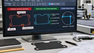
CAD geometry should be checked for duplicate entities, overlapping paths, unintended open contours, small gaps, self-intersections, stray objects, and imported drawing artifacts. The purpose is to make the intended physical cut geometry unambiguous and prevent unintended entities from being interpreted as cutting instructions.
A visually simple drawing can contain significant CAM preparation problems.
CAD Geometry Preparation Errors
| Geometry Issue | Manufacturing Risk | CAD Check | Recommended Correction |
| Duplicate lines | Repeated cutting interpretation | Compare coincident entities | Remove unintended duplicates |
| Overlapping paths | Ambiguous toolpath | Inspect intersections | Consolidate intended geometry |
| Open contours | Incomplete profile interpretation | Run endpoint checks | Close or explicitly define the path |
| Small gaps | Unintended contour breaks | Inspect endpoints at high magnification | Correct endpoint coordinates |
| Self-intersections | Ambiguous profile | Run geometry validation | Redesign the contour |
| Stray entities | Unintended cutting or processing | Inspect drawing extents | Remove irrelevant objects |
| Unsupported splines | Conversion errors | Test export in receiving software | Agree on curve representation |
| Construction lines | Incorrect cut interpretation | Review layer assignments | Isolate non-cutting information |
Important qualification: Not every valid manufacturing design must be represented as one single closed polyline. Some supplier CAD/CAM workflows accept connected lines and arcs, multiple entities, or other curve representations.
The engineering requirement is to communicate the intended physical cut geometry in a representation the supplier can reliably process.
Industry Insight 2 — Clean Geometry Can Matter More Than Visual Complexity
Engineering Observation: A complex profile with correctly defined arcs and connected contours can be easier to process than a visually simple drawing containing duplicate lines and ambiguous entities.
Why It Matters: CAM preparation depends on the quality and interpretation of geometric data, not merely the apparent simplicity of the part.
Practical Recommendation: Prioritize geometric integrity, entity compatibility, and cutting-path clarity over unnecessary simplification of the finished-part design.
Should Cutting Profiles Be Closed Polylines?
A closed polyline is a connected sequence of line or arc segments whose final endpoint joins its starting endpoint. It can be useful for representing a continuous two-dimensional cutting boundary.
However, a closed polyline is not a universal requirement for every precision die-cutting workflow. Some systems accept separate connected entities, while others require specific geometry types or conversion procedures.
Engineers should confirm:
- Whether the supplier accepts lines, arcs, splines, and polylines.
- Whether connected segments must be joined.
- Whether internal contours and external profiles require separate identification.
- Whether small geometric gaps are permitted.
- How the CAM system interprets overlapping or intersecting entities.
- Whether spline conversion is necessary.
The objective is not to force every drawing into one CAD representation. It is to ensure that the receiving system interprets the intended geometry accurately.
How Should Holes, Slots, and Internal Cutouts Be Defined?
Holes, elongated slots, internal windows, and notches should be represented with clearly defined geometry, dimensional references, positional information, and cutting intent. Engineers should identify which features are functionally critical and communicate any restrictions relating to narrow webs, internal corners, and hole-to-edge distances.
A mounting hole, for example, should not be defined solely by its visual position in the drawing.
The engineering drawing should establish:
- Hole diameter or slot width.
- Overall slot length and end geometry.
- Center position or coordinate reference.
- Relationship to datum features.
- Hole-to-edge distance where functionally important.
- Applicable dimensional or positional tolerance.
- Whether the feature is a through-cut or another defined operation.
Internal cutouts should also be distinguished from non-cutting reference geometry.
For asymmetric components, orientation and datum references are particularly important. A correctly sized hole pattern can still produce a functionally incorrect component if its position is interpreted relative to the wrong reference edge.
How Should Through-Cut and Kiss-Cut Features Be Identified?
Through-cut and kiss-cut features must be identified separately because they describe different cutting requirements within a material or laminate structure.
A through-cut generally penetrates the specified material layers to separate the finished component from surrounding stock or to create a fully cut opening.
A kiss-cut generally penetrates a designated surface layer or material combination while retaining an underlying layer, commonly a release liner or carrier.
For adhesive-backed insulation parts, this distinction affects component presentation, handling, and assembly.
CAD Layer and Cutting Intent
| Feature / Layer | Intended Operation | Required Drawing Information | Supplier Confirmation |
| Through-cut profile | Full-depth cutting of defined layers | Profile, affected layers, separation requirement | Confirm process interpretation |
| Kiss-cut profile | Partial-depth cutting | Target layer, retained liner/carrier, removal expectation | Confirm depth-control approach |
| Internal opening | Defined cutout | Geometry, position, criticality | Confirm waste-removal method |
| Reference geometry | No cutting | Reference boundary or assembly context | Confirm exclusion from toolpath |
| Registration mark | Alignment/process reference | Location and purpose | Confirm whether required |
| Inspection reference | Quality verification | Datum or measurement location | Confirm inspection method |
A CAD line by itself cannot communicate the required cutting depth. The supplier needs to understand the material stack-up and the intended relationship between the cutting path and each layer.
Industry Insight 3 — Through-Cut and Kiss-Cut Ambiguity Can Change the Entire Manufacturing Process
Engineering Observation: Identical two-dimensional profiles can represent different manufacturing requirements depending on whether the component is fully separated or retained on a liner.
Why It Matters: The intended cutting depth, retained layers, and part-handling requirements affect process planning and tooling decisions.
Practical Recommendation: Define the laminate construction and cutting intent together. Do not rely on line color or CAD layer name alone to communicate cut depth.
How Should CAD Layers Be Organized?
CAD layers should separate manufacturing geometry from reference information and make different cutting operations easy to interpret. A layer structure should distinguish through-cut profiles, kiss-cut features, dimensions, annotations, construction geometry, and other relevant information.
Illustrative layer names include:
- CUT_THROUGH
- KISS_CUT
- REFERENCE
- DIMENSIONS
- ANNOTATION
- REGISTRATION
These are illustrative naming conventions, not universal standards.
Layer names, colors, and line types should be documented in a drawing legend. Another supplier may use a different naming convention or request separate files. The important principle is consistent interpretation, not compliance with an invented universal color standard.
How Should Material Thickness and Laminate Stack-Up Be Specified?
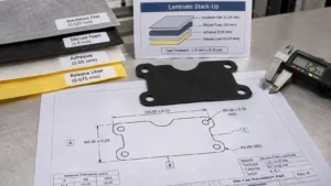
A manufacturing-ready CAD package must identify the material construction associated with the finished component. Nominal base-material thickness and finished laminate thickness are different specifications, particularly when an insulation component contains adhesive, facing films, protective layers, or a release liner.
The drawing should identify the base material, material grade, nominal thickness, layer sequence, adhesive construction, and any relevant cutting-depth requirements.
Material and Laminate Specification
| Material Requirement | CAD / Drawing Input | Manufacturing Impact | Verification Needed |
| Base insulation | Material type and grade | Determines material selection and process considerations | Confirm exact material |
| Nominal thickness | Base material thickness | Influences feature feasibility and tooling review | Verify specification |
| Adhesive backing | Adhesive type and location | Affects lamination and liner construction | Confirm adhesive specification |
| Surface facing | Protective or functional facing | Affects layer identification and finished construction | Confirm facing material |
| Release liner | Liner type and retention requirement | Affects kiss-cut interpretation and handling | Confirm retained layer |
| Carrier film | Carrier type and thickness where relevant | Influences material handling and cutting requirements | Confirm construction |
| Finished laminate | Complete layer sequence | Defines the actual component construction | Confirm finished stack-up |
Base Material Thickness vs. Finished Laminate Construction
These values should never be treated as interchangeable.
For example, an insulation component may contain:
- A base insulation sheet.
- A pressure-sensitive adhesive layer.
- A protective surface film.
- A release liner.
The nominal thickness of the insulation sheet does not describe the entire laminate construction.
Similarly, a release liner may be present during processing but removed during assembly. The engineering drawing should state whether the specified finished-part thickness includes or excludes removable layers.
A CAD design that is easy to manufacture in a thin polymer film may not be equally manufacturable in a thick, compressible foam or a fiber-reinforced insulation composite.
Industry Insight 4 — Material Construction Should Be Defined Before Tooling Review
Engineering Observation: The same CAD profile can create different manufacturing challenges when applied to different material grades, thicknesses, or laminate constructions.
Why It Matters: Tooling feasibility cannot be reliably evaluated from two-dimensional geometry alone.
Practical Recommendation: Include the material specification and complete laminate stack-up with the initial CAD submission rather than postponing material selection until after quotation.
How Should Dimensions and Tolerances Be Defined?
Dimensions and tolerances should communicate the required finished-part geometry, not simply the numerical precision displayed by CAD software. Engineers should identify critical dimensions, functional datums, hole positions, profile requirements, and appropriate measurement conditions.
A drawing tolerance defines an engineering requirement. It does not automatically demonstrate that a particular supplier or cutting process can achieve it.
Dimensions That Deserve Explicit Review
- Overall component length and width.
- Outer-profile geometry.
- Hole diameter and positional accuracy.
- Slot width and length.
- Distance between functional features.
- Hole-to-edge relationships.
- Critical profile characteristics.
- Material thickness requirements.
- Finished laminate dimensions.
A datum is a theoretically exact reference used to establish a measurement or geometric relationship. A consistent datum scheme helps engineering, manufacturing, and quality teams measure the same features from the same references.
ASME Y14.5 and ISO 1101 can provide recognized frameworks for dimensioning and geometric tolerancing. These standards communicate product requirements; they do not establish universal precision die-cutting capability.
Dimensions, Tolerances and DFM
| Drawing Feature | Engineering Concern | Supplier Review | Acceptance Basis |
| Overall dimensions | Component fit | Material and process capability | Agreed dimensional inspection |
| Hole position | Assembly alignment | Datum and positioning method | Drawing tolerance |
| Slot dimensions | Functional clearance | Feature geometry and process suitability | Defined width and length |
| Outer profile | Component boundary | Material deformation and cutting method | Profile requirement |
| Laminate thickness | Assembly stack-up | Material compression and layer construction | Agreed measurement condition |
| Critical edge | Contact or insulation interface | Edge integrity and inspection access | Defined visual or dimensional criteria |
A practical tolerance review should distinguish:
- Critical dimensions: Features directly affecting fit, electrical isolation, thermal interfaces, or assembly performance.
- Functional dimensions: Features influencing installation, alignment, and component interaction.
- Reference dimensions: Informational dimensions that do not independently establish acceptance requirements.
Avoid assigning extremely tight tolerances to every feature without a functional reason.
The drawing defines required product geometry; the supplier must separately demonstrate whether the process can meet it.
Industry Insight 5 — Customers Should Not Assume Universal Die-Cutting Tolerances
Engineering Observation: Dimensional capability varies with material properties, thickness, feature geometry, tooling, process conditions, and inspection method.
Why It Matters: Applying tolerance logic from rigid machined components to compressible insulation materials can create unrealistic acceptance requirements.
Practical Recommendation: Identify functional critical-to-quality dimensions and request a material- and process-specific capability review before approving the production drawing.
Should Engineers Add Kerf or Tooling Compensation to CAD Geometry?
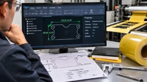
Engineers should generally communicate the required nominal finished-part geometry and agree on any necessary tooling compensation with the manufacturer. Undocumented offsets should not be introduced independently because they can create conflicting interpretations of the intended component dimensions.
Several concepts should be distinguished:
- Nominal geometry: The intended finished-part dimensions.
- Tooling compensation: An adjustment made to account for a particular manufacturing process.
- Cutting allowance: An agreed geometric adjustment associated with the cutting method.
- Material deformation: Changes in geometry resulting from compression, recovery, or other material behavior.
A zero-width CAD line represents a mathematical path, not a guarantee of zero-width physical cutting. The physical result depends on the process, tool geometry, material response, and manufacturing conditions.
Recommended Engineering Communication
- Define the required finished-part geometry.
- Identify critical dimensions and acceptance criteria.
- Provide the original nominal CAD profile.
- Discuss any required compensation with the supplier.
- Document agreed tooling modifications.
- Compare prototype dimensions with the approved drawing.
- Record approved production geometry and revision status.
Industry Insight 6 — The Supplier Should Control Undocumented Tooling Compensation
Engineering Observation: Customer-defined geometry and supplier-managed tooling adjustments serve different purposes.
Why It Matters: Unapproved offsets can cause the manufacturing profile to differ from the nominal engineering requirement.
Practical Recommendation: Keep the approved finished-part CAD geometry as the reference and document any agreed process compensation separately.
How Should Material Direction and Orientation Be Communicated?
Material orientation should be specified whenever the material has a relevant directional characteristic or the component must be installed in a particular orientation.
Potential requirements include:
- Roll direction.
- Fiber orientation, where applicable.
- Surface-facing direction.
- Adhesive-side identification.
- Top and bottom identification.
- Asymmetric component orientation.
- Grain direction or other directional characteristics.
A drawing can include a directional arrow, material orientation note, or separate material specification. Do not add orientation restrictions to materials that have no relevant directional requirement. Instead, establish whether orientation affects performance, processing, or assembly.
How Should CAD Files Account for Die-Cutting DFM?
Design for Manufacturability (DFM) is the engineering review of a component’s design against the requirements and limitations of its intended manufacturing process.
For precision die cutting, DFM review should consider feature geometry, material behavior, tooling accessibility, material support, waste removal, handling, and inspection.
A design that is geometrically valid may still present manufacturing challenges.
Practical DFM Review Matrix
| Design Concern | Potential Issue | Supplier Review | Recommended Action |
| Narrow web | Weak or unstable material connection | Material-specific feasibility | Review spacing and material response |
| Small opening | Feature reproduction difficulty | Tooling and process capability | Validate through engineering review |
| Sharp internal corner | Tooling or geometry limitation | Tool accessibility | Review corner geometry |
| Closely spaced cuts | Material support or separation difficulty | Cutting sequence | Review feature spacing |
| Compressible material | Dimensional variation | Material behavior | Agree on inspection conditions |
| Internal waste | Slug retention or removal concerns | Waste-removal strategy | Identify critical internal features |
| Complex profile | CAM interpretation challenges | Geometry compatibility | Validate exported data |
There is no single universal minimum hole diameter, slot width, or web width applicable to every precision die-cutting application. These limits depend on material grade, thickness, tooling, process, equipment, and quality requirements.
Should Engineers Include Material Nesting in the CAD File?
Material nesting is the arrangement of multiple component profiles within a sheet, roll, or other raw material format to support material utilization and production planning.
Customers should generally prioritize providing an accurate single-part finished geometry and clearly defined orientation constraints. A nesting layout can be provided when relevant, but it should not be assumed to be a universal RFQ requirement.
Before supplying a nesting drawing, clarify:
- Whether the raw material is supplied in sheets or rolls.
- Raw material width and length, where known.
- Whether material direction restricts part orientation.
- Whether multiple parts can be rotated.
- Production quantity.
- Whether the supplier will perform nesting.
- Whether customer-defined nesting is mandatory.
A supplier-managed nesting arrangement may differ from a customer’s preliminary layout because tooling, production sequence, material utilization, and waste-management requirements must also be considered.
How Should CAD Drawing Revisions Be Controlled?
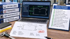
CAD revision control ensures that the engineering drawing, exported geometry, material specification, and manufacturing instructions refer to the same approved design.
A correct CAD file with the wrong revision can still produce the wrong part.
Each released drawing package should identify:
- Part number.
- Drawing number.
- Revision identifier.
- Revision date.
- Change description.
- Approval status.
- Applicable CAD file.
- Matching PDF drawing.
- Superseded file status.
- Supplier acknowledgment.
Recommended Revision Workflow
- Initial design: Create the preliminary CAD model and drawing.
- RFQ release: Submit a clearly marked quotation revision.
- DFM review: Record supplier questions and agreed engineering changes.
- Prototype release: Issue a controlled prototype drawing revision.
- Prototype approval: Document approved geometry and material construction.
- Production release: Confirm that the production drawing and associated files match the approved revision.
Engineering changes should be communicated through a controlled process rather than by silently replacing an attachment with a file carrying the same name.
Industry Insight 7 — Revision Control Is Part of Manufacturing Quality
Engineering Observation: An old CAD file, a newer PDF, and an unsynchronized material specification can describe different products even when the part number is identical.
Why It Matters: Manufacturing and inspection decisions may be made from different revisions if file status is unclear.
Practical Recommendation: Synchronize CAD, PDF, material specifications, and RFQ references at every quotation, prototype, and production release.
What Should Be Included in a Manufacturing-Ready CAD Package?
A manufacturing-ready CAD package should contain sufficient information for the supplier to understand the intended component, evaluate manufacturing feasibility, prepare a quotation, and plan prototype production.
The package should combine editable geometry, an approved engineering drawing, material specifications, cutting requirements, and commercial project information.
CAD Package and RFQ Requirements
| Required Information | Customer Input | Supplier Output | Clarification Risk |
| 2D CAD geometry | DXF, DWG, or accepted format | Geometry review | Unsupported entities |
| Approved drawing | Dimensioned PDF | Drawing interpretation | Conflicting dimensions |
| Material specification | Grade and construction | Material feasibility review | Unspecified material |
| Thickness | Nominal base and laminate thickness | Material confirmation | Incorrect stack-up |
| Cutting instructions | Through-cut and kiss-cut requirements | Process interpretation | Ambiguous cutting depth |
| Critical dimensions | Functional dimensions and tolerances | Capability assessment | Unclear acceptance |
| Orientation | Direction and facing requirements | Manufacturing orientation | Incorrect material alignment |
| Quality requirements | Inspection criteria | Inspection proposal | Undefined acceptance |
| Revision control | Drawing number and revision | Revision acknowledgment | Obsolete geometry |
| Production quantity | Prototype and forecast quantities | Quotation assumptions | Incomplete commercial scope |
Recommended Manufacturing File Package
Part_Number_001/
|
|– CAD/
| |– Part_001_Rev_A.dxf
| `– Part_001_Rev_A.dwg
|
|– DRAWING/
| `– Part_001_Rev_A_Approved.pdf
|
|– MATERIAL/
| `– Material_Specification.pdf
|
`– RFQ/
`– Manufacturing_Requirements.pdf
This is an illustrative folder structure, not a mandatory supplier format.
The package should identify one authoritative revision and make clear which files are approved for quotation, prototyping, or production.
How Can Engineers Validate CAD Files Before Sending Them?
A pre-submission validation workflow should confirm that the exported file is readable, dimensionally correct, geometrically complete, and consistent with the approved engineering drawing.
Engineers should not assume that a successful export guarantees manufacturing readiness.
Pre-Submission CAD Validation Workflow
| Step | Validation Activity | What to Check | Expected Result |
| 1 | Open exported file independently | File readability | File opens correctly |
| 2 | Confirm units | mm or inches | Explicit unit definition |
| 3 | Check critical dimensions | Overall size and reference dimensions | Correct scale |
| 4 | Review cutting contours | Outer and internal geometry | Intended profiles identified |
| 5 | Remove accidental geometry | Duplicates and stray entities | Clean geometry |
| 6 | Check cutting layers | Through-cut and kiss-cut | Clear cutting intent |
| 7 | Verify holes and slots | Position and dimensions | Functional geometry confirmed |
| 8 | Review material notes | Grade and thickness | Complete material definition |
| 9 | Check revision | Drawing number and revision | Consistent document status |
| 10 | Compare CAD with PDF | Geometry and dimensions | No unexplained discrepancies |
| 11 | Confirm supplier compatibility | File version and entity types | Accepted exchange format |
| 12 | Release RFQ package | All required documents | Controlled submission |
Industry Insight 8 — Drawing Ambiguity Often Creates Hidden Quotation Work
Engineering Observation: Missing units, unclear material specifications, and undefined cutting layers require additional interpretation and clarification.
Why It Matters: These questions can affect quotation assumptions, prototype planning, and the likelihood of drawing revisions.
Practical Recommendation: Resolve basic geometry, material, and cutting-intent questions before releasing the RFQ. Ask the supplier to document any remaining assumptions.
What Should Suppliers Check During DFM Review?
A supplier DFM review should establish whether the submitted design, material construction, and manufacturing requirements can be interpreted and evaluated using the supplier’s actual process capabilities.
The review should cover:
- File readability.
- Geometry completeness.
- Material compatibility and availability.
- Laminate and layer requirements.
- Critical features.
- Required tolerances.
- Tooling feasibility.
- Waste removal.
- Prototype and production quantity.
- Inspection method.
- Packaging requirements.
- Open technical questions.
A supplier should distinguish between confirmed manufacturing requirements, assumptions used for quotation, and items requiring customer approval.
Industry Insight 9 — The Best RFQ Package Minimizes Engineering Assumptions
Engineering Observation: A file package that clearly defines geometry, material, function, volume, and acceptance requirements allows the supplier to focus on genuine manufacturing questions rather than reconstructing the customer’s intent.
Why It Matters: Fewer hidden assumptions reduce the risk of inconsistent quotation, tooling, prototype, and inspection interpretations.
Practical Recommendation: Treat the RFQ package as a controlled engineering communication package, not merely a collection of attachments.
Hypothetical Engineering Example: Preparing CAD Files for a Custom EV Battery Insulation Pad
Hypothetical Engineering Example
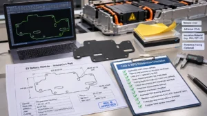
Consider an EV battery Tier 1 supplier developing a custom insulation pad for a battery module. The component contains an external profile, mounting holes, elongated slots, internal cutouts, adhesive backing, and a release liner. The engineering team intends to request a quotation and prototype samples from a precision die-cutting supplier.
Step 1 — Define the Battery Application
Identify the component’s installation location and function. Determine whether the pad provides electrical insulation, thermal protection, mechanical separation, or a combination of functions. Identify the relevant assembly interfaces and critical characteristics.
Step 2 — Confirm the Insulation Material
Select the specified material or identify candidate materials requiring supplier evaluation. Material selection should consider the application’s electrical, thermal, mechanical, and environmental requirements.
Step 3 — Identify the Laminate Construction
Document the intended sequence of base insulation material, adhesive layer, protective facing if applicable, and release liner. Identify which layers remain in the assembled component.
Step 4 — Verify Drawing Units
Set the agreed measurement system and confirm 1:1 model-space geometry. Use an overall dimension and a mounting-hole spacing as independent checks.
Step 5 — Export the Agreed CAD Format
Prepare the DXF, DWG, or other format accepted by the supplier. Retain the original native CAD file where appropriate.
Step 6 — Review Duplicate and Open Geometry
Inspect the external profile, internal cutouts, slots, and mounting holes. Remove unintended duplicates and investigate any open contours.
Step 7 — Identify Cutting and Non-Cutting Layers
Separate through-cut geometry, kiss-cut geometry, reference geometry, dimensions, and manufacturing annotations. Attach a drawing legend.
Step 8 — Define Through-Cut and Kiss-Cut Requirements
Specify whether the external profile must separate the finished part from surrounding stock. Identify features that require cutting through selected layers while retaining the release liner.
Step 9 — Specify Critical Dimensions
Identify overall dimensions, mounting-hole positions, slot sizes, and critical distances affecting assembly. Define relevant datums and tolerances.
Step 10 — Mark Inspection Requirements
Specify which dimensions require verification and whether inspection should be performed with the liner attached or removed. Define required visual or functional checks.
Step 11 — Confirm Material Orientation
Indicate adhesive-side orientation, surface-facing direction, and any relevant directional characteristics.
Step 12 — Attach the Approved PDF Drawing
Include a dimensioned PDF containing the material specification, manufacturing notes, and inspection requirements.
Step 13 — Record Revision Information
Ensure the DXF, DWG, PDF, and material specification identify the same revision.
Step 14 — Include Prototype Quantity and Annual Demand
Provide the requested sample quantity and estimated production volume so the supplier can evaluate the appropriate quotation and manufacturing scope.
Step 15 — Request Supplier DFM Review
Ask the supplier to evaluate file compatibility, material feasibility, cutting intent, critical dimensions, tolerances, tooling feasibility, and outstanding technical questions.
What Is Ready for Quotation?
The supplier can receive a controlled CAD package containing the intended part geometry, identified cutting features, material construction, critical dimensions, drawing revision, and requested quantities.
What Still Requires Supplier Confirmation?
- Accepted CAD format and version.
- Material availability.
- Laminate compatibility.
- Through-cut and kiss-cut interpretation.
- Tooling feasibility.
- Critical tolerance capability.
- Inspection method.
- Prototype requirements.
What Must Be Verified During Prototyping?
- Finished-part dimensions.
- Hole and slot positions.
- External profile.
- Edge condition.
- Adhesive and liner behavior.
- Material orientation.
- Assembly fit.
- Functional performance against approved engineering requirements.
Prototype approval is not complete production qualification. A successful prototype confirms the evaluated sample against its agreed criteria. Production release may require additional process validation, quality documentation, and customer approval.
Common CAD Preparation Mistakes That Affect Precision Die Cutting
| No. | Mistake | Potential Manufacturing Impact | Corrective Action |
| 1 | Sending files without confirmed units | Incorrect dimensional interpretation | Specify units and verify a reference dimension |
| 2 | Exporting at an unintended scale | Incorrect finished geometry | Validate 1:1 model-space dimensions |
| 3 | Leaving duplicate cutting lines | Ambiguous or repeated cutting instructions | Remove unintended duplicate entities |
| 4 | Ignoring open contours | Incomplete profile interpretation | Check and resolve intended endpoints |
| 5 | Mixing construction lines with cutting geometry | Incorrect CAM interpretation | Separate reference and cutting layers |
| 6 | Mixing through-cut and kiss-cut features | Incorrect layer penetration requirements | Define cutting intent separately |
| 7 | Using undefined CAD layers | Supplier interpretation errors | Add descriptive layer names and a legend |
| 8 | Omitting the material grade | Unclear material selection | Identify grade or approved candidate |
| 9 | Omitting adhesive or liner construction | Incorrect laminate assumptions | Provide a layer-by-layer specification |
| 10 | Forgetting critical dimensions | Incomplete acceptance requirements | Identify functional dimensions and datums |
| 11 | Applying unrealistic tolerances | Unachievable or unnecessarily restrictive requirements | Request a process capability review |
| 12 | Sending only an unverified screenshot or raster image | No reliable editable geometry | Submit accepted CAD data and an approved drawing |
| 13 | Assuming PDF is automatically machine-ready | Missing or unsuitable cutting geometry | Confirm vector data and supplier compatibility |
| 14 | Adding undocumented tooling compensation | Nominal geometry becomes ambiguous | Keep nominal geometry and document agreed offsets |
| 15 | Sending conflicting drawing revisions | Incorrect part manufacturing | Synchronize CAD, PDF, and material revisions |
| 16 | Ignoring orientation requirements | Incorrect material alignment | Add orientation arrows and assembly notes |
| 17 | Omitting waste-removal considerations | Unclear internal-feature processing | Identify relevant internal waste and handling requirements |
| 18 | Submitting unnecessary customer nesting layouts | Conflicting production assumptions | Agree on nesting responsibility with the supplier |
| 19 | Ignoring finished-part inspection requirements | Undefined product acceptance | Specify inspection features and conditions |
| 20 | Forgetting prototype and production quantities | Incomplete quotation scope | Include sample quantity and annual forecast |
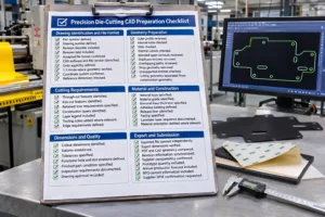
Precision Die-Cutting CAD Preparation Checklist
Drawing Identification and File Format
- Part number defined.
- Drawing number defined.
- Revision identifier included.
- Revision date included.
- Accepted file format confirmed.
- CAD software and file version identified where relevant.
- Units explicitly defined.
- 1:1 model-space geometry verified.
- Coordinate system confirmed.
- Reference dimension checked.
Geometry Preparation
- Outer profile reviewed.
- Internal holes checked.
- Slots checked.
- Internal cutouts checked.
- Intended open contours reviewed.
- Duplicate entities removed.
- Overlapping paths reviewed.
- Stray geometry removed.
- Unsupported entities checked.
- Cutting geometry separated from construction geometry.
Cutting Requirements
- Through-cut features identified.
- Kiss-cut features identified.
- Retained liner requirements specified.
- Construction layers identified.
- Layer legend included.
- Tooling notes added where relevant.
- Edge requirements defined.
Material and Construction
- Material type specified.
- Material grade identified.
- Nominal base thickness specified.
- Adhesive backing defined.
- Release liner identified.
- Facing specified.
- Laminate layer sequence documented.
- Material orientation defined where relevant.
Dimensions and Quality
- Critical dimensions identified.
- Datums established.
- Tolerances specified.
- Functional hole and slot positions defined.
- Finished-part condition specified.
- Inspection requirements documented.
- Drawing approval recorded.
Export and Submission
- Exported file opened independently.
- Export dimensions verified.
- PDF and CAD geometry compared.
- Revision information synchronized.
- Supplier compatibility confirmed.
- Prototype quantity included.
- Annual production forecast included.
- RFQ contact information included.
- Supplier DFM confirmation requested.
RFQ Checklist for Precision Die-Cut Insulation Components
A quotation request should provide enough technical and commercial information for the supplier to assess the intended product and identify outstanding assumptions.
Customer Submission Requirements
- Material type.
- Material grade or candidate.
- Material thickness.
- Adhesive and facing construction.
- DXF, DWG, or supplier-accepted CAD file.
- Approved PDF drawing.
- Part number.
- Drawing revision.
- Critical dimensions.
- Required tolerances.
- Cutting instructions.
- Through-cut and kiss-cut requirements.
- Hole and slot specifications.
- Material orientation.
- Quality requirements.
- Inspection criteria.
- Prototype quantity.
- Annual volume.
- Packaging requirements.
- Requested quotation scope.
- Required technical documentation.
Supplier Confirmation Requirements
- File compatibility.
- Material availability.
- Feature manufacturability.
- Required tooling.
- Tolerance feasibility.
- Prototype requirements.
- Open drawing questions.
- Inspection approach.
- Quotation assumptions and exclusions.
If information is incomplete, the supplier should identify the quotation assumptions rather than implying that all manufacturing requirements have already been confirmed.
How Boost Insulation Supports Custom Die-Cut Insulation Projects
Boost Insulation presents its business around precision die cutting, thermal and electrical insulation materials, thermal management solutions, custom converting, and engineering-oriented manufacturing support. The company website also describes engineering consultation, material selection, DFM support, prototyping, CNC processing, lamination, and custom manufacturing capabilities.
For project-specific work, customers should confirm the exact material grade, thickness, file compatibility, tolerance feasibility, adhesive construction, and prototype requirements with Boost Insulation before production release.
A complete CAD and material specification package gives a converting supplier a clearer basis for discussing tooling feasibility, prototype requirements, critical tolerances, and production expectations.
Suggested verified website pages for the WordPress editor to check before publication:
- Boost Insulation homepage: https://boostinsulation.com/
- About / manufacturing capabilities: https://boostinsulation.com/about/
- Aerogel insulation and DFM solutions: https://boostinsulation.com/products/aerogel-insulation/
- Technical FAQ: https://boostinsulation.com/faq/
Do not create internal links to planned but unpublished articles.
Frequently Asked Questions
1. What CAD file format is best for precision die cutting?
DXF is often a practical format for transferring two-dimensional cutting geometry because it supports editable vector entities. DWG may be preferable when the supplier needs the original CAD drawing structure. PDF should accompany the geometry as an approved engineering reference. The best format depends on the supplier’s CAD/CAM software, supported file versions, and geometry requirements. Always confirm compatibility before exporting.
2. Can I send a PDF instead of a DXF file for die cutting?
Yes, a supplier may be able to review a PDF drawing for quotation or manually reconstruct geometry when necessary. However, a PDF does not automatically provide suitable editable cutting data. A dimensioned PDF communicates product requirements, while a compatible DXF or other accepted CAD format provides more direct access to vector geometry. Ask the supplier whether PDF-only submission is acceptable for the intended project.
3. Do CAD cutting contours need to be closed?
Not universally. Closed contours can make continuous cutting profiles easier to interpret, but some CAD/CAM workflows accept connected lines, arcs, or other entity combinations. The requirement depends on the supplier’s software and manufacturing process. Engineers should inspect unintended gaps, overlapping segments, and incomplete boundaries, then confirm the accepted geometry representation before submitting the production file.
4. How should through-cut and kiss-cut layers be shown in CAD?
Identify through-cut and kiss-cut geometry separately using descriptive layer names and a drawing legend. Through-cut generally penetrates the specified material layers, while kiss-cut penetrates designated surface layers while retaining an underlying liner or carrier. Include the laminate sequence, retained-layer requirements, and inspection criteria. Agree on layer names and cutting conventions with the supplier because no single color or naming system applies universally.
5. What tolerances should be specified for precision die-cut parts?
Specify tolerances according to functional requirements, material characteristics, and the intended inspection method. Identify critical overall dimensions, hole positions, slot dimensions, and profile requirements. Do not assume that every material can achieve the same dimensional accuracy. The drawing establishes the required geometry, while the supplier must separately assess whether the selected material and cutting process can meet the specified acceptance criteria.
6. Should I add cutting compensation or offsets to my CAD drawing?
Generally, provide the required nominal finished-part geometry and discuss any necessary tooling compensation with the supplier. Undocumented offsets can create disagreement about whether the drawing represents the finished component or a modified tooling profile. Cutting allowance, material deformation, and tool geometry should be evaluated within the agreed manufacturing process. Record any approved compensation separately from the authoritative product definition.
7. What information should be included in a die-cutting RFQ?
A precision die-cutting RFQ should include accepted CAD geometry, an approved dimensioned PDF, part number, revision, material grade, nominal thickness, adhesive and liner construction, cutting instructions, critical dimensions, tolerances, and inspection requirements. Include prototype quantity, estimated annual demand, packaging requirements, and requested documentation. These details help the supplier evaluate material suitability, tooling feasibility, manufacturing assumptions, and quotation scope.
8. How can I check whether my CAD file is ready for manufacturing?
Open the exported file independently, confirm drawing units, and verify critical dimensions against the approved engineering drawing. Remove unintended duplicates, overlapping paths, stray entities, and ambiguous contours. Separate cutting and reference layers, define material construction, identify critical tolerances, and synchronize drawing revisions. Finally, confirm file compatibility and request a supplier DFM review before prototype or production release.
Request a CAD and DFM Review for Custom Die-Cut Insulation Parts
Preparing a manufacturing-ready CAD package is an important step in developing reliable custom insulation components. A complete drawing should communicate the finished-part geometry, material construction, cutting requirements, dimensional controls, and quality expectations.
For an initial technical review, prepare:
- DXF, DWG, or another supplier-accepted CAD file.
- Approved PDF engineering drawing.
- Material requirements and material grade.
- Nominal thickness and laminate construction.
- Adhesive, facing, and release-liner specifications.
- Critical dimensions and tolerances.
- Through-cut and kiss-cut instructions.
- Material orientation requirements.
- Prototype quantity and annual production forecast.
Recommended project workflow:
CAD Drawing + Material Specification + Manufacturing Requirements → DFM Review → Prototype Quotation
OEM, Tier 1, manufacturing engineering, and technical procurement teams can submit their engineering drawings and material requirements to Boost Insulation for project-specific technical discussion.
The objective is to establish a clear manufacturing definition before tooling and production commitments are made.
Related Posts:

How Does Battery Aerogel Insulation Work in EV Packs?
How Do You Choose Battery Aerogel Insulation for EVs?

How Do You Test Silicone Foam Recovery in EV Battery Pads?

What Is Battery Aerogel Insulation for EV Battery Packs?
How Does a Mica Insulation Sheet Compare With FR4 Boards?
What Thermal Conductivity Should EV Aerogel Insulation Have?
 root