
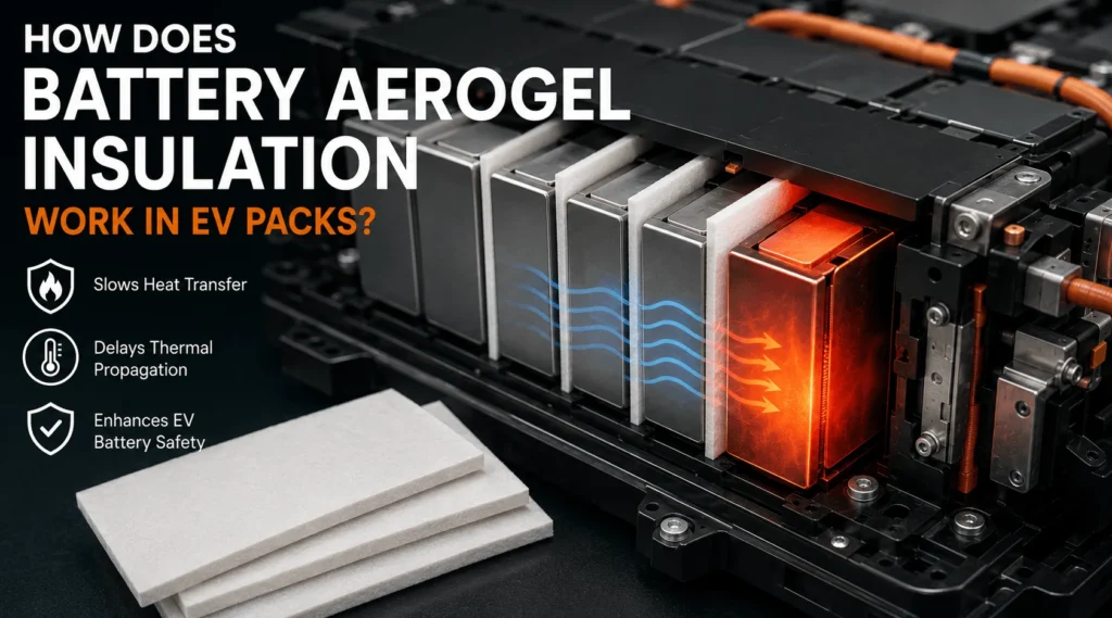
How Does Battery Aerogel Insulation Work in EV Packs?
Table of Contents
When a single EV cell releases intense heat, what actually prevents the cell beside it from following? Cooling hardware may remove everyday operating heat, but an abnormal event develops too quickly and too locally for routine cooling alone. This is where a thin aerogel barrier can change the heat-transfer path – and potentially change the outcome of the entire module.
<a href="https://boostinsulation.com/products/aerogel-insulation/">Battery aerogel insulation</a> works by placing a nano porous, low-thermal-conductivity barrier between EV cells or battery structures. Its fine pore network reduces solid and gas-phase heat transfer, while the converted part limits direct contact and radiant exposure. During a cell failure, the barrier slows heat reaching neighboring cells, buying time for detection, warning, venting, cooling, and other pack-level safety measures.
Engineering Takeaways
- Aerogel is a thermal barrier, not a thermal interface material, it is selected to resist heat flow rather than move heat to a cold plate.
- The finished die-cut laminate—not only the raw aerogel core—must be evaluated for thickness, compression, dielectric behavior, flame response, edge integrity, dust, and adhesive aging.
- Cell-to-cell protection is a system problem. Aerogel performance depends on cell chemistry, state of charge, vent direction, cooling, mechanical compression, bypass paths, and module-level validation.
The Working Principle in One Sentence
Battery aerogel insulation works by increasing thermal resistance across a very small gap, so heat from a hot or failing cell reaches the protected cell more slowly.
The word slowly is important. Aerogel is not an active extinguisher, a coolant, or an electronic control. It is a passive barrier. It cannot remove the initiating fault, but it can reduce the rate of energy transfer across a selected boundary. In a well-designed EV pack, that delay supports the rest of the safety architecture: sensors identify the abnormal event, the battery management system issues a warning, vents direct hot gases away from vulnerable components, cooling hardware absorbs part of the energy, and structural barriers help contain the event.
The practical question for engineers is therefore not simply whether a material is called aerogel. It is whether the complete, installed, die-cut part maintains enough thermal resistance for long enough under the cell chemistry, state of charge, compression, vent direction, and abuse condition defined by the vehicle program.
Why Aerogel Has Such Low Thermal Conductivity
Aerogel is a porous solid with a nano scale network and a very high volume of trapped gas. In silica aerogel, the solid skeleton is sparse and the pores are small enough to restrict gas motion. This structure reduces the two heat-transfer paths that dominate many conventional materials conduction through a continuous solid and conduction or convection through gas-filled voids.
The U.S. Department of Energy notes that aerogel thermal conductivity is strongly related to mean pore size and connectivity between the nano particles in the skeleton. When pores remain in the nano scale range, gas movement is restricted; when the solid network is less connected, less heat can travel through the solid phase. This is the physical basis for achieving high insulation performance in a thin part.
Battery-grade aerogel is normally not a fragile laboratory monolith. It is reinforced with fibers, scrims, binders, or flexible carriers so that it can be handled, laminated, transported, and die-cut. These additions make the part manufacturable, but they also create additional heat paths. The conductivity of the finished composite is therefore higher than that of an ideal aerogel monolith and must be evaluated as an installed construction rather than inferred from a raw-material headline value.
At elevated temperatures, radiative transfer becomes more important. Opacifiers, surface layers, ceramic components, and hybrid constructions may be used to reduce radiation or improve hot-side integrity. A room-temperature conductivity number is useful for screening, but it does not describe the complete response to a thermal-runaway event.
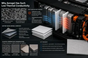
The Four Heat Paths an Aerogel Barrier Must Control
Conduction through the cell face: Closely packed prismatic or pouch cells can transfer heat across a broad contact area. Aerogel adds through-thickness thermal resistance between those faces, slowing the temperature rise of the neighboring cell.
Conduction through pack hardware: Busbars, frames, end plates, fasteners, cooling plates, and enclosure components can bypass the inter-cell barrier. Aerogel cannot compensate for every metallic bridge. The design must identify parallel heat paths and interrupt them with electrical films, structural breaks, thermal isolation, or additional barriers where necessary.
Radiation from hot surfaces and flames: A failing cell may expose nearby parts to high surface temperatures or direct flame. The aerogel core can resist heat flow, while surface films or inorganic layers may protect the core and reduce line-of-sight exposure. The hot-side skin must remain attached and stable long enough to protect the cold side.
Hot gas and particle flow: Vent gases can travel around a flat barrier through gaps, cutouts, cable routes, and poorly controlled edges. Aerogel mainly resists heat through its thickness; it does not automatically block a jet that goes around the part. Vent clearance, vent direction, edge sealing, cover geometry, and gas-channel design are therefore part of the barrier system.
How It Works During Normal EV Operation
During normal charging and driving, aerogel reduces unwanted lateral heat transfer between protected regions. This is different from a thermal interface pad, which is selected to move heat efficiently from a cell or electronic component to a cooling plate. Aerogel is a thermal resistor; a thermal interface material is a thermal conductor.
That distinction affects placement. A low-conductivity barrier placed in the intended cooling path can increase cell temperature and worsen temperature uniformity. Aerogel should be placed across heat paths that the engineer wants to suppress, while cooling plates, gap fillers, gels, and thermal pads should remain in the paths intended to remove routine heat.
In some module designs, the barrier also reduces thermal cross-talk between cells, so a temporary hot spot in one location has less immediate influence on the neighboring cell. The benefit depends on the complete thermal circuit, and the module should still be modeled and tested to confirm that the barrier does not interfere with required cooling.
How It Works During Thermal Runaway
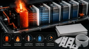
Thermal runaway produces a short-duration, high-intensity heat event. The initiating cell can heat its neighbors by conduction, radiation, flame, and vent gases. If a neighboring cell reaches its own critical conditions, the event can propagate through the module.
Aerogel delays this sequence by reducing the heat flux across the protected face. The neighboring cell heats more slowly, which may keep its internal temperature below the onset threshold during the most severe part of the initiating event. Even when the barrier does not stop propagation indefinitely, added delay can be valuable because it expands the response window for warning, vehicle evacuation, electrical isolation, active cooling, or fire-service intervention.
Open-access experimental work on 18650 cells found that increasing aerogel-felt thickness from 1 mm to 3 mm and 6 mm improved the delay of thermal-runaway propagation. Other module studies have also reported suppression or delay with silica aerogel sheets, while showing that results vary with cell energy, chemistry, state of charge, thickness, trigger method, and module configuration. The engineering lesson is not that one thickness always works. It is that barrier performance is inseparable from the abuse scenario and the pack geometry.
UN Regulation No. 100 includes thermal-propagation provisions for rechargeable electrical energy storage systems, reflecting the industry’s focus on protecting occupants from hazardous conditions after a thermal event. A material datasheet can support design, but only the module or vehicle-level test can demonstrate the behavior of the complete system.
What a Production Aerogel Part Is Made Of
A production battery aerogel part is normally a multilayer conversion rather than a bare aerogel core. The stack may include a fiber-reinforced silica aerogel sheet a PET or polyimide encapsulation film, a fiberglass or nonwoven carrier, a pressure-sensitive adhesive, and a release liner. Each layer solves a practical problem: reinforcement improves handling, film limits dust, adhesive controls placement, and the liner protects the adhesive until assembly.
These added layers also change the thermal, electrical, mechanical, and flame behavior. A film can melt or shrink before the core loses its insulation function. An adhesive can soften, flow, char, or create a local heat bridge. A dense edge seal can conduct more heat than the aerogel center. A carrier can improve tensile strength but add an in-plane path for heat.
For this reason, the drawing should define the complete bill of materials and finished thickness, not only the aerogel grade. The test specimen used for approval should match the production stack-up, adhesive coverage, edge seal, compression, and orientation as closely as practical.
Where Battery Aerogel Insulation Is Installed
Between prismatic cell faces.
This is the most direct cell-to-cell application. The barrier covers the broad face while respecting vent zones, locating features, tabs, weld areas, and sensor routes.
Between pouch cells or cell groups.
Pouch modules must manage swelling and stack pressure. Aerogel may be paired with a compressible layer rather than carrying the full mechanical load by itself.
Around cylindrical-cell groups.
Aerogel can be converted into strips, rings, sleeves, or shaped partitions. The design challenge is controlling three-dimensional gaps and directing vent gases away from adjacent cells.
At module boundaries.
Larger sheets can slow heat transfer into end plates, side plates, covers, electronics compartments, and adjacent modules.
Under pack covers or above cell arrays.
Aerogel may be part of a fire-protection assembly that delays heat reaching the passenger compartment or external structure. This application can require larger area coverage, stronger surface skins, and resistance to puncture or jet exposure.
Near high-voltage components.
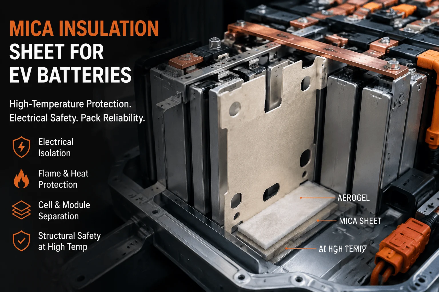
Aerogel can be combined with dielectric films, mica, or flame-retardant polycarbonate where thermal and electrical separation are both required. The finished construction must meet the actual voltage, creepage, clearance, contamination, and aging requirements.
Why Thickness and Compression Change Performance
Thermal resistance increases with effective thickness and decreases as conductivity rises. That simple relationship explains why a thicker aerogel barrier usually delays heat transfer longer, but thickness cannot be selected in isolation. EV module gaps are limited, and every additional millimeter affects energy density, stack pressure, enclosure size, and manufacturing tolerance.
Compression can reduce the effective thickness of the aerogel, increase contact between solid fibers, and change conductivity. It may also damage fragile regions or force the material into vent clearances. The correct input is not the supplier’s free-state thickness. It is the retained thickness under minimum, nominal, and maximum assembly compression after aging and vibration.
Contact conditions matter as well. A small air gap can add thermal resistance during normal operation, but it may collapse under swelling or allow hot gases to circulate during failure. A fully bonded surface improves location control yet can add adhesive heat paths. The module validation sample should reproduce the intended contact pressure, adhesive pattern, and hardware tolerances.
Why Films, Adhesives, and Edge Seals Matter
Encapsulation film improves cleanliness and assembly. It can reduce aerogel dust, strengthen the surface, and provide a printable or bondable skin. The trade-off is that the film may have lower temperature resistance than the core. The engineer should understand whether the film must survive the event or whether it can recede while the core continues to function.
Pressure-sensitive adhesive is often applied in full coverage, strips, frames, or locating dots. Full coverage provides strong placement but can increase cost and heat transfer. A perimeter frame may reduce thermal bridging but requires adequate seal width and peel strength. Small locating areas reduce material use but demand accurate assembly.
Edge seals control dust and prevent the reinforcement from fraying, but dense polymeric seal lands can become bypass paths. The drawing should define minimum seal width, maximum seal encroachment, allowable exposed core, corner radii, pull-tab location, and any no-adhesive zones. These details frequently determine whether a concept can be converted consistently at production volume.
Electrical Insulation and Flame Ratings: Important Limits
Silica-based aerogel cores are generally nonconductive, but the complete part must be assessed for electrical use. Surface film, adhesive, reinforcing fibers, moisture, contamination, crushed edges, and conductive dust from neighboring processes can affect dielectric strength and insulation resistance. Electrical qualification should use the finished part at the intended thickness, compression, temperature, humidity, and aging condition.
Flame-retardant classifications require similar discipline. UL explains that UL 94 ratings are small-scale material tests conducted under controlled conditions and that V-0 and VTM-0 are different classifications based on different specimen configurations. A raw film’s rating, a core’s rating, and a finished laminate’s response are not automatically interchangeable.
UL 94 is useful evidence for material behavior after a small flame exposure. It is not a thermal-runaway propagation certification, a direct-flame jet test, or a complete battery-pack approval. The program should specify exactly which layer and thickness require a rating, then validate the complete barrier and pack against the relevant abuse conditions.
How Polycarbonate Insulation and Silicone Foam Work With Aerogel
Aerogel is strongest when it is assigned the thermal-barrier function rather than forced to solve every module problem. Flame-retardant polycarbonate can add rigidity, puncture resistance, electrical separation, and controlled geometry. Silicone foam can manage cell swelling, assembly tolerance, vibration, sealing, and pressure distribution. Aerogel contributes high through-thickness thermal resistance.
A hybrid construction might use a polycarbonate frame to support and locate a thin aerogel insert, while silicone foam manages compression around the perimeter. Another design may use aerogel on the hot side, a dielectric film for electrical isolation, and foam only in zones that require controlled pressure. The correct layer order depends on the direction of heat, venting, electrical risk, and assembly sequence.
Hybrid parts can reduce assembly steps, but lamination creates new interfaces and change-control risks. The converter should evaluate differential thermal expansion, adhesive compatibility, compression set, edge alignment, liner removal, and the ability to inspect every critical layer.
| Material | Primary Role | Strength | Watch Point | Typical Use |
| Aerogel | Thermal resistance | High insulation per thickness | Compression, edges, dust | Cell-to-cell barrier |
| FR Polycarbonate | Electrical / structural | Rigid, puncture resistant | Polymer temperature limits | End plates, frames, covers |
| Silicone Foam | Compliance / sealing | Gap filling and vibration control | Compression set and flame class | Tolerance and pressure layer |
| Mica | High-temperature fire barrier | Inorganic and arc resistant | Brittleness and thickness | Pack covers and fire shields |
How Precision Die Cutting Preserves the Thermal Function
Die cutting is not merely a shape-making process. It determines whether the thermal barrier covers the intended area, avoids vents, maintains seal width, sits flat, and remains free from tears or crushed zones. A small dimensional error can expose a direct conduction path or interfere with cell spacing.
Tool choice depends on thickness, reinforcement, film construction, tolerance, annual volume, and edge requirements. Flatbed cutting can be suitable for prototypes, thicker laminates, and large parts. Rotary die cutting can support high-volume roll processing when the stack-up has stable web handling. Digital or laser processes may help early development but must be checked for heat-affected edges, fumes, contamination, and dimensional repeatability.
A strong DFM review should address minimum web width, corner radius, internal cutouts, pull tabs, adhesive zones, kiss-cut depth, liner split, edge-seal land, nesting yield, inspection datums, packaging direction, and part removal. The converter should also control dust extraction, tool wear, material conditioning, lot traceability, and protection from crushing during shipment.
Boost Insulation positions itself as an IATF 16949-certified manufacturer of custom EV battery thermal-management and insulation parts, including precision conversion of aerogel, mica, polyimide films, polycarbonate, and related materials. For a technical buyer, the relevant evidence is the ability to translate a performance target and drawing into a controlled, repeatable finished part.
How to Validate an Aerogel Barrier
Level 1 – Material screening. Review thermal conductivity, thickness, density, maximum-use-temperature evidence, tensile or compression behavior, moisture response, flame classification, dielectric properties, and chemical compatibility. Confirm the test method and specimen construction behind every value.
Level 2 – Converted-part validation. Test the actual laminate after die cutting, encapsulation, adhesive application, and aging. Measure finished thickness, mass, flatness, compression behavior, peel strength, dimensional stability, insulation resistance, dielectric withstand, flame response, dust, edge integrity, and packaging effects.
Level 3 – Module and pack validation. Install production-representative parts with actual cells, hardware, cooling, compression, vents, busbars, covers, and sensors. Use the program’s defined trigger and state of charge. Measure hot-side and cold-side temperatures, propagation time, vent behavior, electrical isolation, structural damage, and warning performance.
The design should also be challenged at tolerance extremes. A nominal sample can conceal risk caused by the thinnest barrier, highest compression, smallest gap, weakest adhesive, worst seal alignment, or most energetic cell lot. Validation should include the conditions most likely to reduce thermal resistance or create a bypass path.
Validation principle: material data qualifies the grade, converted-part tests qualify the laminate, module and pack abuse tests qualify the system. Do not use one level as a substitute for another.

Industry Insight: Five Changes Affecting Aerogel Programs
- Higher cell energy raises the value of thin barriers: As cells store more energy and modules become more compact, engineers need more thermal resistance from less space. This favors high-performance insulation but makes defects, gaps, and compression more consequential.
- Cell-to-pack architectures shift responsibility to materials: Removing traditional module hardware improves volumetric efficiency but can eliminate incidental separation and heat-sinking mass. Barrier parts must be designed earlier, not added after the cell layout is frozen.
- Fast charging increases thermal-design coupling: Routine heat rejection and abuse protection must coexist. A barrier that improves propagation resistance but blocks the intended cooling path is not a successful design.
- Buyers increasingly request finished-part evidence: A conductivity value for raw aerogel no longer answers questions about an encapsulated, adhesive-backed, compressed, die-cut component. Supplier qualification is moving toward traceable stack-ups and converted-part test data.
- Multifunctional parts are replacing single sheets: Aerogel is increasingly combined with films, polycarbonate, silicone foam, mica, adhesives, and locating features. This can simplify assembly, but it demands stronger DFM, interface control, and change management.
A Practical Selection Workflow
First- define the failure boundary: Identify the initiating cell, the cell or component that must be protected, the dominant heat paths, the vent direction, and the critical cold-side temperature.
Second- define the timing target: Specify whether the barrier must prevent propagation, delay it for a defined period, protect a cover, or maintain electrical isolation during and after the event.
Third- define the mechanical window: Provide the nominal gap, tolerance stack, compression range, cell swelling, vibration environment, and available edge-seal land.
Fourth- define the finished construction: Select the aerogel core, reinforcement, films, adhesive pattern, liner, electrical layer, foam or polycarbonate support, and packaging method.
Fifth- prototype at multiple conditions: Test at least the expected nominal condition and the combination most likely to reduce retained thickness or create a heat bypass.
Finally- freeze the complete specification: Control the exact raw grades, approved alternates, thickness, density, film, adhesive, liner, seal geometry, tooling, inspection plan, packaging, and change-notification process.
Common Reasons Aerogel Barriers Underperform
Selecting from room-temperature conductivity alone.
The hot-side environment, radiation, compression, and surface layers can dominate performance during a severe event.
Treating aerogel as a universal fire shield.
A flat barrier cannot stop hot gases or flames that bypass it through an open vent channel.
Ignoring compression loss.
A nominal 2 mm sheet that is heavily compressed may deliver much less thermal resistance than expected.
Using material-level flame data as pack evidence.
UL 94 and other coupon tests do not replicate cell venting or module-level thermal runaway.
Allowing uncontrolled layer substitutions.
A change in film, adhesive, liner, carrier, or seal method can alter thickness, flammability, dielectric behavior, and assembly performance.
Skipping converter DFM until tooling.
Early review can improve seal width, reduce dust, simplify liner removal, increase material yield, and avoid late changes to cell or module hardware.
Frequently Asked Questions
Does battery aerogel insulation cool EV cells?
No. It normally resists heat transfer. Routine heat should be moved through dedicated thermal-interface materials and cooling hardware.
Can aerogel stop every thermal-runaway event?
No material can guarantee this across every battery design. Aerogel may delay or prevent propagation under a defined configuration, but the complete module must be tested.
What thickness works best between cells?
There is no universal thickness. It depends on cell energy, chemistry, gap, compression, allowable cold-side temperature, venting, and other heat paths.
Is aerogel electrically insulating?
Many silica aerogel composites are non conductive, but the finished laminate must pass the project’s dielectric and insulation-resistance tests after aging and compression.
Does aerogel need UL94 V-0?
Some programs require a particular flame rating. Confirm the applicable material, thickness, test configuration, and whether the requirement applies to a layer or the finished part.
Can aerogel be adhesive-backed?
Yes. The adhesive pattern and grade should be selected for the cell surface, aging conditions, temperature, flame behavior, and assembly process.
Can aerogel be combined with PC and silicone foam?
Yes. PC can provide structure and dielectric protection, while silicone foam manages tolerance and pressure. The complete stack-up must be validated.
What should be sent for a quotation?
Provide the 2D drawing, available gap, compression range, target thermal delay, material or test requirements, film and adhesive needs, prototype quantity, annual volume, packaging, and schedule.
Turn the Thermal Concept Into a Manufacturable Part
Battery aerogel insulation works because its nano porous structure slows heat through a thin section. In an EV pack, however, the thermal mechanism is only the starting point. The final result depends on retained thickness, contact pressure, hot-side skin, edge sealing, vent routing, dielectric layers, adhesive aging, precision die cutting, and system-level validation.
A useful supplier conversation should begin with the thermal and mechanical boundary conditions, not with a request for the cheapest aerogel sheet. Share the cell format, module drawing, available gap, compression range, vent location, target cold-side temperature or propagation delay, voltage requirement, flame requirement, annual volume, and prototype timeline. Boost Insulation can review the stack-up, provide DFM feedback, and convert aerogel, polycarbonate, silicone foam, and related insulation materials into production-ready battery components.
| Need a Custom Cell-to-Cell Aerogel Barrier?
Send the cell format, available gap, compression range, target thermal delay, dielectric requirement, drawing, annual volume, and prototype quantity. Boost Insulation can review the stack-up and prepare a manufacturable die-cut sample for validation. |
Technical Sources
- Boost Insulation, EV battery insulation, aerogel conversion, thermal-management, and quality-system information. Source
- U.S. Department of Energy. Development of nano porous super insulation: pore size, particle connectivity, and thermal conductivity. Source
- United Nations Economic Commission for Europe. UN Regulation No. 100, Revision 3: REESS safety and thermal-propagation provisions. Source
Liu Q. et al. Influence of Aerogel Felt with Different Thickness on Thermal Runaway Propagation of 18650 Lithium-ion Battery. Electrochemistry 90 (2022), 087003. DOI: 10.5796/electrochemistry.22-00048. Source - Tang J. et al. Suppressing thermal runaway propagation of nickel-rich lithium-ion battery modules using silica aerogel sheets. Process Safety and Environmental Protection 179 (2023), 199-212. Source
- UL Solutions, UL 94 flame classifications, test methods, and the distinction between V-0 and VTM-0. Source
Related Posts:
What Are EV Battery Module Solutions and How Do They Work?
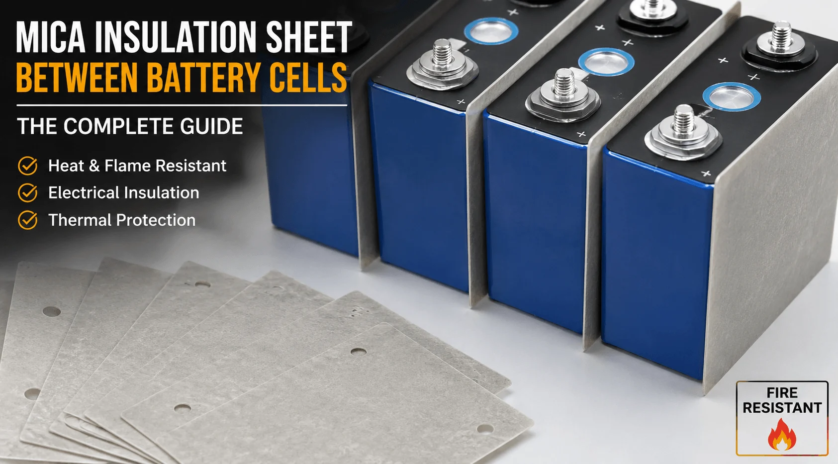
Can a Mica Insulation Sheet Work Between Battery Cells?
How Do You Choose a Flame Retardant PC Supplier?
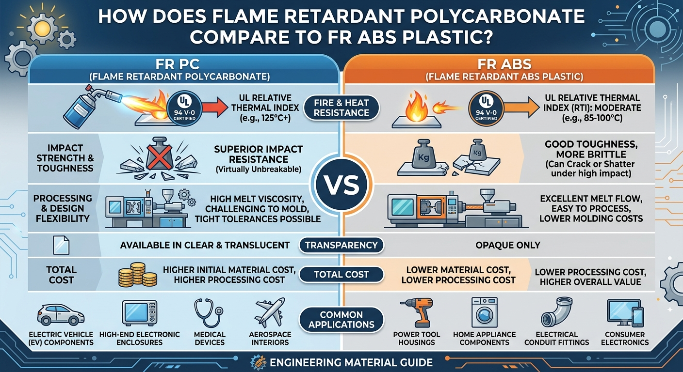
How Does Flame Retardant Polycarbonate Compare to FR ABS Plastic?
What Makes Flame Retardant Polycarbonate Ideal For Batteries?
How Does a Mica Insulation Sheet Protect EV Batteries?
 betty wong
