What Are EV Battery Module Solutions and How Do They Work?
Table of Contents
Here’s a question that catches many EV developers off guard: if two electric vehicles share the same battery chemistry and the same nominal capacity, why can one deliver 400 kilometers of real-world range while the other struggles to reach 300—and fails its safety certification on the way? The difference rarely lives in the cells themselves. It lives in the battery module solution. Whether you’re an automotive OEM designing your next EV platform, a Tier 1 supplier evaluating procurement partners, or an industrial equipment manufacturer integrating electric drivetrains for the first time, understanding what EV battery module solutions are—and precisely how they work—is the engineering and business foundation you cannot afford to overlook.
⚑ QUICK ANSWER
1. The EV Battery Hierarchy: Where Modules Fit
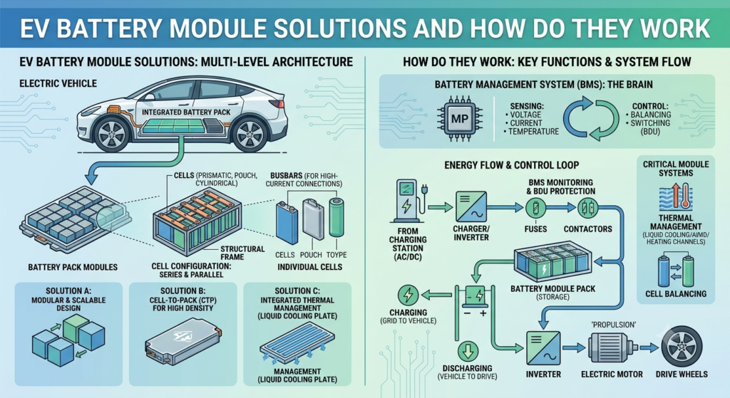
To understand battery module solutions, it helps to visualize the complete hierarchy of an EV’s energy storage architecture. This hierarchy—Cell → Module → Pack → Vehicle—defines how energy is stored, managed, and delivered at every level of the system.
- Cell: The fundamental electrochemical unit. A single lithium-ion cell stores energy through the movement of lithium ions between anode and cathode. Individual cells operate at 3.2–4.2V and range from under 5Wh (small cylindrical) to 300Wh+ (large prismatic).
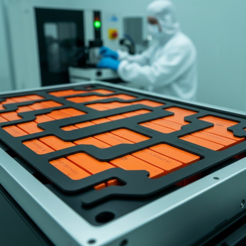
- Module: Multiple cells are grouped, mechanically constrained, electrically connected in series/parallel combinations, and thermally managed. This is the battery module—the unit that battery module solution providers design and manufacture.
- Pack: Multiple modules are integrated with pack-level BMS, high-voltage contactors, cooling manifolds, fusing, and a structural enclosure to create the battery pack ready for vehicle installation.
- Vehicle Integration: The complete pack connects to the motor inverter, onboard charger, and vehicle control unit to form the complete EV powertrain.
The module layer is where the most consequential engineering decisions are made. Cell selection, thermal architecture, electrical topology, and mechanical design at the module level cascade upward to determine pack performance, safety, and longevity over the vehicle’s entire service life. This is precisely why battery module solutions—rather than bare cells—are the primary procurement unit for serious EV development programs.
Key Takeaway: The module is not a commodity component between cells and pack—it is where cells become a system, and where the engineering quality of that system is determined.
2. Core Components of an EV Battery Module Solution
A professionally engineered EV battery module solution is not simply cells placed in a box. It is a precision assembly of interdependent components, each performing a specific function within the overall system. Understanding each component is essential for evaluating module solutions and suppliers.
2.1 Cell Array: The Energy Foundation
The cell array is the heart of any module. Battery module solutions are designed around one of three primary cell formats, each with distinct advantages:
- Cylindrical cells (18650, 21700, 4680): Highly standardized, mechanically robust, and benefit from decades of manufacturing maturity. The 4680 format, pioneered by Tesla, exemplifies the shift toward larger cylindrical cells that improve energy density and simplify pack assembly.
- Prismatic cells: Rectangular aluminum-cased cells that are self-supporting and enable high packing efficiency. Widely used in Asian OEM platforms; provide excellent thermal contact area and stable geometry under cycling.
- Pouch cells: Flexible laminate-cased cells offering the highest gravimetric energy density potential. Require external compression frames but enable highly compact module geometries. Preferred in applications where mass and volume are critical.
Cell chemistry also defines the module’s performance profile: LFP (lithium iron phosphate) delivers maximum cycle life, inherent thermal stability, and lower cost; NMC (nickel manganese cobalt) maximizes energy density for premium range applications; NCA (nickel cobalt aluminum) is optimized for peak performance. The module solution is engineered specifically for the chemistry it employs—a module designed for LFP cannot simply be repopulated with NMC cells without significant redesign.
2.2 Module Housing and Structural Frame
The module housing simultaneously provides mechanical protection, dimensional stability under thermal and mechanical loading, structural interface to the battery pack, and in some designs contributes active thermal conduction via contact with external cooling surfaces.
Housing materials are selected based on performance and cost requirements. Extruded or die-cast aluminum is the preferred choice for performance EV applications—lightweight, thermally conductive, corrosion-resistant, and structurally stiff. Formed steel offers lower cost at higher mass, still used in cost-optimized commercial vehicle programs. Engineering thermoplastics provide electrical insulation and mass reduction, increasingly used in combination with aluminum structural elements for specialized module architectures.
For pouch cell modules, the housing also performs the critical function of compression management—maintaining uniform stack pressure on pouch cells throughout their operational life to prevent capacity fade caused by electrode delamination.
2.3 Busbar and Electrical Interconnection Network
Busbars are the low-resistance conductors that electrically connect cells in series and parallel configurations within the module. The busbar design—material, cross-sectional area, connection method, and thermal expansion accommodation—directly determines:
- Electrical resistance, and therefore I²R heat generation and system efficiency losses
- Peak current-carrying capacity and short-circuit withstand capability
- Mechanical tolerance of cell swelling, thermal expansion differential, and vehicle vibration
- Manufacturing yield and long-term field reliability
Modern battery module solutions use laser-welded aluminum or copper busbars for cell terminal connections, with flexible interface designs that accommodate cell swelling cycles, thermal expansion differentials between materials, and manufacturing dimensional tolerances. Inadequate busbar design—including insufficient cross-section, poor weld quality, or inadequate expansion accommodation—is one of the most frequently cited root causes of field failures in EV battery systems.
2.4 Battery Management System (BMS) Integration Interface
Every battery module solution includes a BMS integration interface—the electrical and communication architecture that enables the BMS to monitor and protect every cell in the module with the resolution and speed required for safe, optimized operation.
- Cell Voltage Sensing (CVS) harness: Individual measurement connections from each cell group to the BMS measurement circuits, enabling per-cell voltage monitoring to within ±1mV resolution.
- Temperature sensors (NTCs): Multiple thermistor sensors distributed throughout the cell array provide thermal mapping across the module, enabling the BMS to detect localized hotspots before they become safety events.
- Cell Supervision Circuit (CSC) / Slave BMS board: In advanced module designs, a dedicated PCB embedded within the module handles local cell-level measurement, balancing, and fault detection, communicating with the master BMS via CAN bus, SPI, or proprietary protocol.
The BMS integration approach is a critical differentiator between module solution providers. A tightly integrated, well-calibrated BMS interface enables precise state-of-charge (SOC) and state-of-health (SOH) estimation, proactive cell balancing to maximize usable capacity, early fault detection before safety thresholds are breached, and controlled safe shutdown upon fault condition detection.
2.5 Thermal Management System (TMS)
Thermal management is arguably the most consequential engineering challenge in battery module design. Lithium-ion cells perform optimally within a narrow temperature window (typically 15–35°C for most NMC/LFP chemistries) and degrade rapidly—or become unsafe—when temperature operation falls outside that range consistently.
EV battery module solutions employ one or more of the following thermal management strategies, selected based on power requirements, charging rate targets, and operating environment:
- Active liquid cooling: Cooling plates fabricated from aluminum or stainless steel, with serpentine or parallel coolant channels, are integrated into the module structure and contact cell surfaces through thermally conductive interface materials (TCIM). This is the most effective and widely adopted approach for passenger and commercial EV applications requiring sustained high power.
- Phase Change Materials (PCM): Wax-based or salt-based materials encapsulated within the cell interstices absorb peak heat loads through their solid-to-liquid phase transition, providing passive thermal buffering. Used in applications where active cooling infrastructure is not available.
- Immersion cooling (dielectric fluid): An emerging technology in which cells are directly immersed in thermally conductive, electrically non-conducting fluid. Enables extremely high heat removal rates and is becoming commercially viable for ultra-fast charging (4C+) applications.
- Air cooling: Forced airflow through cell arrays. Lower cost and lower thermal mass requirement, but significantly lower heat removal capacity. Largely superseded in passenger EV applications by liquid cooling, though still used in some commercial vehicle and stationary applications.
The thermal management system chosen for a battery module solution determines the allowable sustained C-rate, fast charging capability, minimum/maximum operating temperature, and—critically—calendar and cycle life. Under-investing in thermal management at the module design stage is one of the costliest decisions an EV program can make.
2.6 Safety Features and Protection Architecture
Safety engineering is embedded at every level of a professional battery module solution, not added as an afterthought at the pack level:
- Venting channels and gas exhaust pathways: Designed pathways allow cell vent gas—produced under abuse or fault conditions—to exit the module in a controlled direction without building pressure inside the cell array.
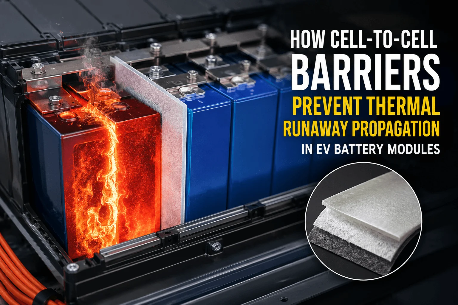
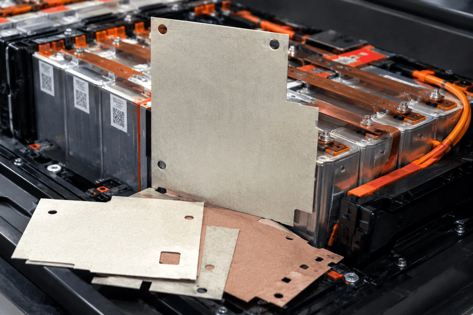
- Thermal propagation barriers: Ceramic fiber sheets, mica plates, aerogel blankets, or intumescent materials positioned between cell groups physically inhibit the spread of heat from a thermal runaway event in one cell to adjacent cells, providing critical time for protective action.
- Electrical isolation barriers: Multiple isolation layers between live HV conductors and accessible module exterior surfaces, validated to automotive HV isolation standards.
- Module-level fusing: Current-limiting fuses or fusible links at the module terminal protect against external short circuits and wiring fault currents.
- Ingress protection (IP67/IP69K): Sealing against water and particulate ingress, validated by standardized water immersion and pressure wash tests per IEC 60529.
Key Takeaway: Safety in a battery module is not a single feature—it is a layered system. Each barrier, pathway, and sensor contributes to a defense-in-depth architecture that must function correctly even when individual components fail.
3. How EV Battery Module Solutions Work: Operational Sequence
Understanding how a battery module solution functions in real-world operation brings all the components above into a dynamic, integrated system. Here is the operational sequence across three key scenarios:
3.1 Normal Discharge (Vehicle Driving)
- The vehicle’s motor controller requests current from the battery pack via the high-voltage bus.
- The pack-level BMS closes the main contactors, enabling current flow from the cell array through the module busbar network to the motor inverter.
- The BMS integration interface continuously measures individual cell voltages, distributed temperatures, and total pack current at frequencies of 10–1000Hz depending on the operating condition.
- The thermal management system removes heat generated by cell internal resistance (I²R losses) and electrochemical inefficiencies, maintaining cells within the target operating temperature window.
- The BMS applies balancing current to equalize cell SOC across the module during operation.
- If any cell voltage drops below its minimum threshold or temperature exceeds its limit, the BMS triggers protective action: reducing requested current or initiating a controlled, safe shutdown.
3.2 Charging (AC or DC Fast Charging)
- The onboard charger (AC charging) or DC fast charger delivers current to the pack’s high-voltage bus.
- Current flows through the module terminals and busbar network into the cell array in the reverse direction from discharge.
- The BMS monitors charge progress continuously, managing cell balancing to equalize state-of-charge across all cells within and between modules.
- The thermal management system removes heat generated during charging—particularly significant during DC fast charging where heat generation rates can be 3–5× higher than during normal discharge.
- The BMS terminates charging when all cells reach their upper voltage limit, preventing overcharge that would cause irreversible capacity loss or safety events.
3.3 Thermal Event Response (Abnormal Condition)
- A cell enters thermal runaway due to an internal short circuit, manufacturing defect, or abuse condition.
- Cell vent gas and heat are directed by the module’s venting channels away from adjacent cells in the designed exhaust direction.
- Thermal propagation barriers slow the conduction of heat to adjacent cell groups, providing time for the safety system to respond.
- The BMS detects the rapid cell voltage collapse and temperature spike, immediately triggering emergency contactor opening to isolate the pack from the high-voltage bus.
- The module housing contains the initial event, preventing direct external exposure to flames or toxic gases during the critical response window.
Key Takeaway: The three-scenario operational sequence above reveals why module solution quality cannot be assessed from a datasheet alone. How a module behaves under fault conditions—not just during normal operation—is the ultimate measure of engineering quality.
4. EV Battery Module Architectures: CTM, CTP, and CTB
The battery module solution industry is undergoing a significant architectural transition that directly affects how modules are designed, manufactured, and integrated into vehicles. Understanding these architectures is essential for aligning your procurement strategy with where the technology is heading.
| Architecture | Energy Density | Repairability | Best Application |
| Cell-to-Module-to-Pack (CTM) | Highest | Excellent | Commercial EVs, buses, trucks |
| Cell-to-Pack (CTP) | High | Limited | Passenger EVs, high-volume OEMs |
| Cell-to-Body/Chassis (CTB) | Highest | Very Limited | Next-gen passenger platforms |
Cell-to-Module-to-Pack (CTM) — The Proven Foundation
The classic architecture: cells are assembled into discrete modules, and modules are assembled into packs using standardized mechanical and electrical interfaces. CTM provides excellent repairability—damaged or degraded modules can be replaced without full pack replacement—standardized module interfaces that support supplier flexibility, and well-established validation and certification pathways. Most commercial EV applications (trucks, buses, construction equipment, marine EVs) continue to use CTM due to its serviceability advantages and architectural modularity.
Cell-to-Pack (CTP) — The Performance Trend
Pioneered by CATL and adopted by a growing number of passenger EV OEMs, CTP eliminates the traditional discrete module layer by integrating cells directly into the pack structure using structural adhesives and pack-level thermal management. CTP improves volumetric energy density (by eliminating redundant module housing mass and volume—typically improving pack energy density by 10–15%) and reduces part count and manufacturing complexity. The trade-off: repairability is significantly reduced. Damaged cells require full pack replacement rather than module swap, increasing warranty repair costs and reducing end-of-life value.
Cell-to-Body/Chassis (CTB/CTC) — The Next Frontier
The most advanced architecture integrates the battery pack directly into the vehicle’s structural body or chassis, using the cells and pack enclosure as a structural load-bearing component of the vehicle frame. Pursued by BYD (Blade Battery CTB platform), Tesla’s structural pack, and others, CTB/CTC maximizes energy density and reduces total vehicle mass—but introduces entirely new engineering challenges around safety compliance, repairability, insurance, and standardization. For module solution providers, CTB/CTC is driving demand for new forms of cell-direct integration technology and structural adhesive systems.
5. Key Performance Parameters to Specify and Evaluate
When evaluating or specifying a battery module solution, the following quantitative parameters define performance and must be precisely aligned with your application requirements. Misalignment on any of these parameters can be costly to correct after module selection is locked.
| Parameter | Typical Range | Application Significance |
| Energy Density | 150–250 Wh/kg (NMC); 90–160 Wh/kg (LFP) | Key driver of range per kg of module mass |
| Volumetric Density | 250–400 Wh/L | Determines pack size for a given range target |
| Cycle Life | 1,000–4,000 cycles to 80% capacity | LFP modules typically outperform NMC here |
| Continuous C-Rate | 0.5C – 3C depending on chemistry | Governs sustained power delivery |
| Peak C-Rate | Up to 10C (5–10 sec) | Critical for acceleration & regen braking |
| Operating Temp. | -30°C to +55°C (with thermal management) | Wider range requires more capable TMS |
| IP Rating | IP67 minimum (automotive standard) | IP69K for high-pressure wash applications |
| Nominal Voltage | Module-level: 24V – 96V typical | Determined by series cell count |
| DC Internal Resistance | < 1 mΩ per 100Ah (high-quality modules) | Lower = better power delivery & less heat |
| Calendar Life | 10–15 years at 25°C typical use | Key metric for commercial vehicle TCO |

6. What to Look For in a Battery Module Solution Supplier
Choosing a battery module solution partner is one of the highest-stakes procurement decisions in any EV development program. The supplier you select becomes a long-term engineering and supply chain partner whose technical capability and organizational stability will affect your program for years. Here is what serious buyers evaluate:
Cell Sourcing Depth and Qualification Rigor
Does the supplier have established, audited relationships with Tier 1 cell manufacturers—CATL, Samsung SDI, LG Energy Solution, Panasonic, BYD, EVE Energy? Can they provide full cell traceability documentation, incoming inspection protocols, and cell-level performance data? Cell quality is the single largest determinant of module performance, and a supplier without robust, documented cell sourcing and qualification protocols represents a critical program risk that cannot be mitigated downstream.
Thermal Management Engineering Capability
Can the supplier perform their own thermal simulation (CFD analysis), design their own cooling architectures, and validate thermal performance on dedicated test rigs? Suppliers who depend on external engineering consultants for thermal design introduce unacceptable risk and lead-time exposure into programs where thermal performance is a competitive differentiator. Ask to see thermal simulation results and physical validation data from comparable applications before proceeding.
BMS Development and Vehicle Integration Support
Is the BMS integrated into the module solution by the supplier’s own engineering team, or outsourced to a third-party BMS vendor without application-specific calibration? Can the supplier support your vehicle control unit (VCU) integration requirements across the CAN/LIN/Ethernet interface stack? BMS calibration for specific cell chemistries, aging models, and operating conditions is a deep technical competency—one that should be verified through reference checking with existing customers before being assumed.
Safety Certification Expertise and Track Record
Which international standards has the supplier certified against, and for which specific products and configurations? Key standards for EV battery modules include: UN 38.3 (transportation safety), IEC 62619 (stationary/industrial), GB 38031 (China automotive), ISO 26262 (functional safety), UL 2580 (US EV batteries), and ECE R100 (European vehicle type approval). A supplier who cannot clearly articulate their certification history, scope of approval, and certification body relationships is almost certainly not a fit for serious OEM production programs.
Manufacturing Scale, Quality Systems, and Process Control
What is their current manufacturing capacity, and what is their demonstrated ramp capability? Do they operate under IATF 16949 (automotive quality management) or equivalent system certification? What in-process controls exist for the critical module manufacturing operations: electrode contamination prevention, busbar torque and weld quality control, thermal interface material application consistency, and 100% electrical end-of-line testing protocols? These are not hypothetical questions—the answers directly predict field quality and warranty exposure.
Configurability: Standard Platform vs. Custom Design
Does the supplier offer a configurable standard module platform, fully custom module design from scratch, or both? Standard platforms offer faster time-to-market and lower engineering risk, with performance proven in existing applications. Custom designs allow optimized fit to unusual form factor, voltage, or thermal requirements. The most capable suppliers offer modular configurability: a proven standard architecture with application-specific customization of voltage (series cell count), capacity (parallel cell count), form factor, and interface—balancing speed-to-market with application optimization.
Procurement Tip: Before finalizing any battery module solution supplier, request a site visit to their manufacturing facility, ask for three customer references from comparable applications, and demand a detailed engineering review of their proposed module design for your application. The quality of that engineering review will tell you more about a supplier’s capability than any marketing datasheet.
7. Common Mistakes EV Programs Make in Module Sourcing
Even experienced engineering teams make avoidable—and expensive—mistakes when sourcing battery module solutions. These are the most consequential:
- Optimizing for cell cost, not module total cost of ownership (TCO): The lowest-cost cells do not produce the lowest TCO when cycle life degradation rate, warranty claim rates, and thermal management system cost are properly modeled over 10 years. Evaluate module solutions on verified 10-year TCO, not purchase price per kWh.
- Underspecifying the thermal management requirement: Thermal management that appears adequate at ambient 25°C in a controlled lab test frequently fails in real-world deployment at -20°C northern winters or 45°C desert operating environments. Specify your complete operating temperature envelope from the first day of project definition and demand module validation data across that full range.
- Treating BMS selection as an afterthought: BMS selection and module solution selection are interdependent decisions that must happen in parallel. A BMS algorithm poorly matched to cell chemistry, aging characteristics, and module architecture is a leading cause of premature range degradation, early capacity loss, and field safety incidents—all of which are exceptionally expensive to address after production launch.
- Ignoring mechanical durability requirements: Automotive and industrial EV applications subject battery modules to sustained road vibration (random vibration per ISO 16750-3 or MIL-STD-810), shock events, chemical splash exposure, and extreme temperature cycling. Modules that pass initial lab acceptance tests but fail in field vibration environments represent one of the costliest failure modes in commercial EV programs.
- Failing to audit supply chain depth: A battery module solution is only as reliable as its deepest single-source dependency. Know exactly where your cells, busbars, thermal interface materials, BMS ICs, and module housings originate—and whether your supplier has supply chain concentration risk that could halt your production at any point.
8. Trends Reshaping EV Battery Module Solutions in 2025–2027
The battery module solution landscape is evolving faster than any other segment of the EV supply chain. These trends are most consequential for buyers and developers evaluating module solutions today:
- Sodium-ion module solutions: Pioneered by CATL’s first-generation sodium-ion cells and BYD’s Eagle platform, sodium-ion battery modules offer a lithium-free chemistry with strong cycle life and superior cold-temperature performance, at potentially lower raw material cost. Module solution providers are actively adapting module architectures for sodium-ion cell formats and voltage requirements.
- Immersion cooling integration in passenger EVs: Dielectric fluid immersion cooling, previously confined to stationary energy storage and niche EV applications, is moving into mainstream passenger EV platforms in response to 800V architectures and 4C+ fast charging requirements. Module solutions designed for direct cell immersion represent a significant near-term growth segment.
- Structural adhesive integration replacing mechanical fasteners: Advanced structural adhesive systems from suppliers such as Henkel, Sika, and 3M are enabling lighter, more thermally integrated module architectures that replace traditional bolted or welded mechanical assemblies—reducing mass, improving thermal contact, and enabling new form-factor flexibility.
- AI-enabled BMS platforms in module solutions: Next-generation BMS integration platforms use machine learning algorithms to continuously refine SOC/SOH estimation models based on in-use data, predict cell-level degradation before it affects performance, and optimize thermal management strategies dynamically. Module solution providers who offer AI-enabled BMS integration are positioned to deliver measurably longer-lived battery systems.
- All-solid-state cell module compatibility: As solid-state battery cells from QuantumScape, Solid Power, Toyota, and Samsung SDI approach commercial availability, module solution providers must develop new compression management architectures—solid-state cells require very different stack pressure profiles than liquid-electrolyte cells, demanding new module housing and compression system designs.
9. Conclusion: Your Competitive Advantage Starts at the Module Level
Every high-performing, long-lasting, and commercially successful electric vehicle begins with a great battery module solution. The performance your customers experience behind the wheel—range, charging speed, cold-weather capability, long-term reliability—is determined, in large part, by the engineering quality, thermal architecture, and manufacturing precision of the battery modules powering the system.
Whether you’re specifying a battery module solution for the first time or re-evaluating your current supplier for a next-generation platform, the decisions you make at the module level ripple through every dimension of vehicle performance, safety, cost of ownership, and regulatory compliance. The module is not a commodity component. It is the core technical differentiator of your EV program.
The buyers and developers who understand module solution engineering today—who can ask the right questions of suppliers, evaluate TMS capability, challenge BMS integration quality, and model true TCO—will build more reliable, safer, and more competitive electric vehicles than those who treat battery modules as a procurement line item.
Related Posts:
How Do Cell-to-Cell Barriers Prevent Thermal Runaway?
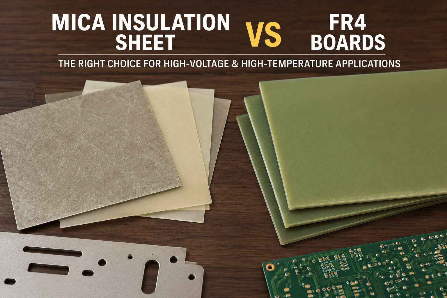
How Does a Mica Insulation Sheet Compare With FR4 Boards?
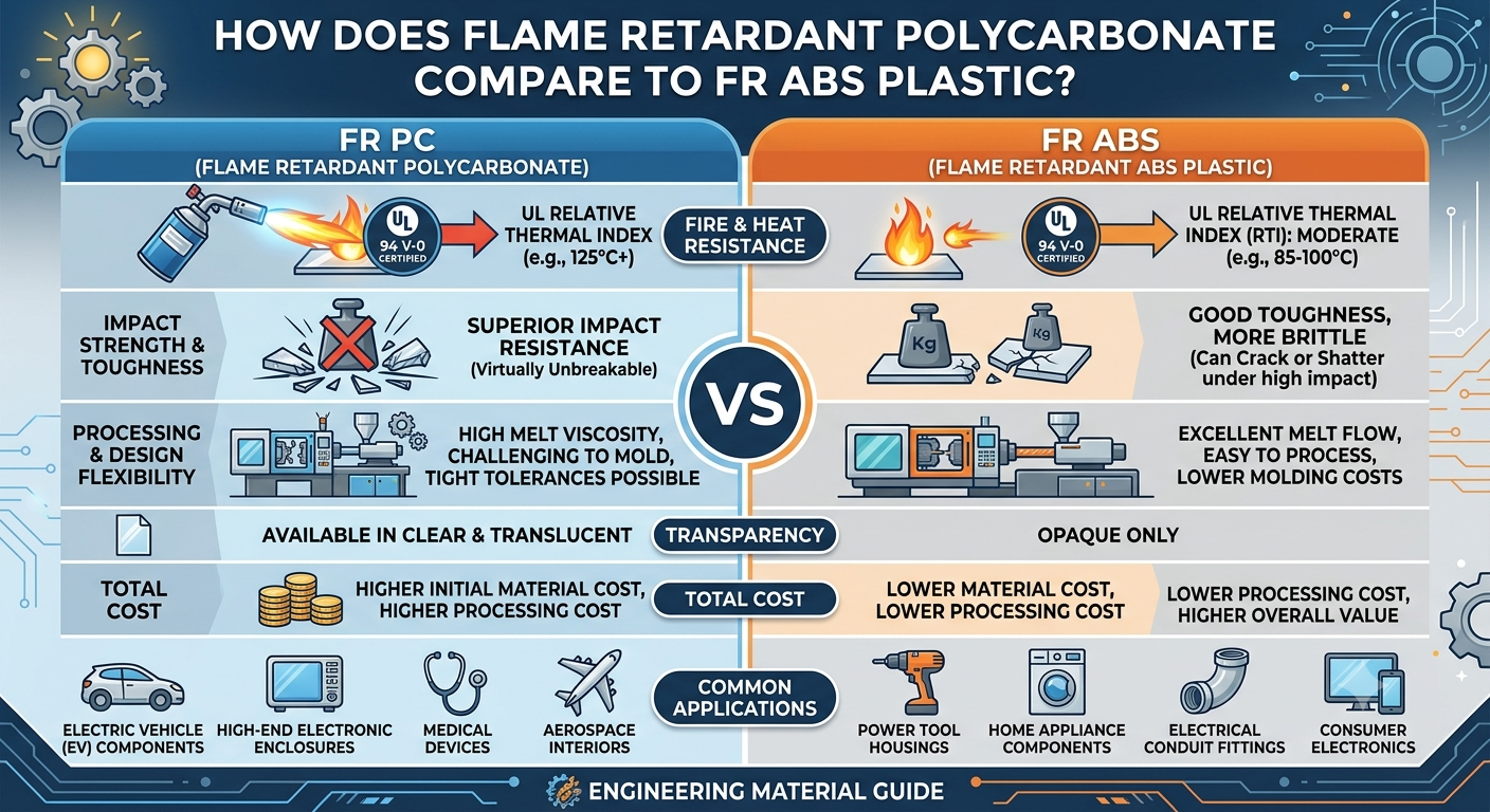
How Does Flame Retardant Polycarbonate Compare to FR ABS Plastic?
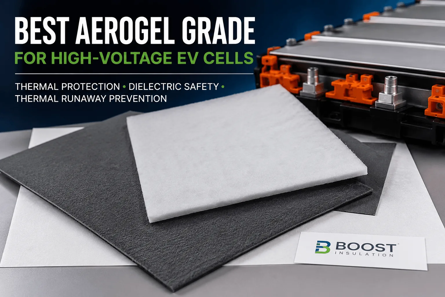
Which Aerogel Grade Is Best for High-Voltage EV Cells?
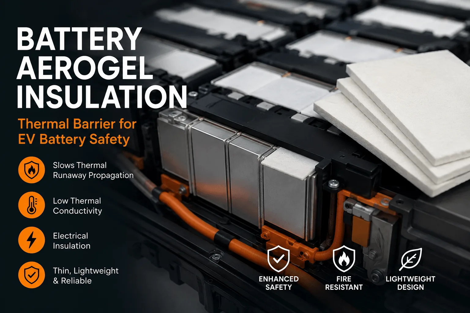
What Is Battery Aerogel Insulation for EV Battery Packs?
What Is a Mica Insulation Sheet for EV Battery Packs?
 betty wong