
How Does a Mica Insulation Sheet Protect Battery Pack Lids?
Table of Contents
The battery-pack lid may sit only millimeters above cell vents, busbars, wiring, and structural ribs. What happens when one cell releases a high-temperature jet that strikes the cover and spreads sideways across seams, fasteners, and adhesive joints? Without an engineered under-lid barrier, the cover can become a secondary heat source, an electrical fault surface, or a burn-through path toward the vehicle structure.
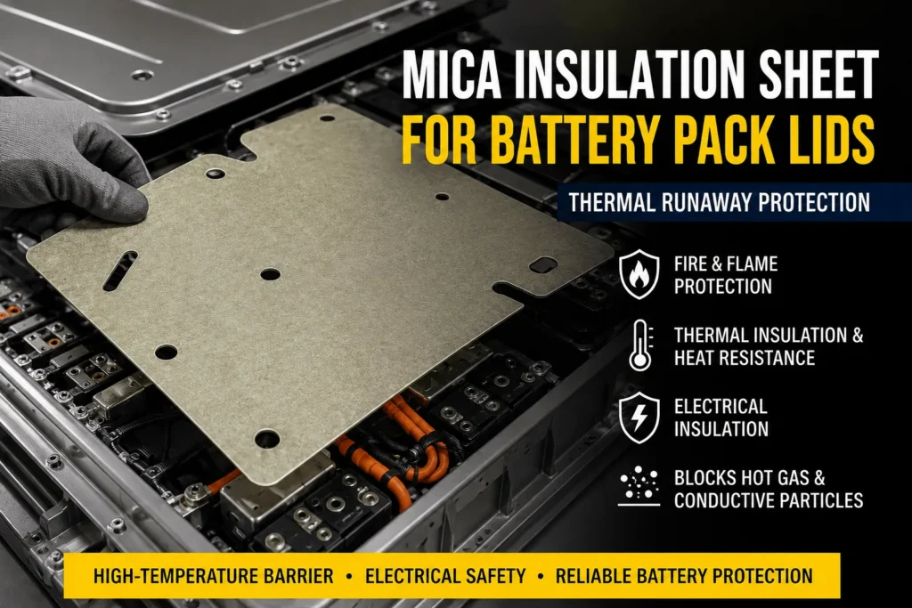
| A mica insulation sheet protects battery-pack lids by forming a high-temperature, electrically insulating barrier between the cell array and the cover. It resists direct flame, hot gas, radiant heat, and particle impact; delays heat transfer into aluminum, steel, or composite lids; and helps prevent conductive ejecta from bridging busbars to the cover. The sheet must cover the real vent-plume footprint, remain attached around ribs and openings, preserve pressure-relief paths, and be validated at the finished thickness with the actual lid, mounting method, cells, and thermal-runaway test. |
Mica Insulation Sheet for Battery Pack Lids: Quick Design Guide
| Lid Risk | Mica Contribution | Typical Construction | Critical Validation |
| Vent flame and hot gas | Creates a durable flame-facing barrier | Reinforced phlogopite or segmented mica | Jet path, burn-through, backside temperature |
| Radiant and conducted heat | Delays lid heating | Mica or mica-aerogel composite | Heat flux, air gap, lid substrate |
| Conductive particles | Separates ejecta from lid and HV hardware | Rigid or glass-backed mica | Edges, seams, fasteners, post-test contamination |
| High-voltage fault | Maintains dielectric coverage near metal lid | Mica or mica-PC laminate | Voltage, creepage, humidity, post-fire insulation |
How a Mica Insulation Sheet for Battery Pack Lids Works
A mica under-lid part is installed on the cell-facing surface of the battery-pack cover or on a supporting frame immediately below it. The part may be one large die-cut liner, several segmented panels, a flexible mica laminate, a rigid board, or a multilayer barrier that combines mica with aerogel, silicone foam, polycarbonate, glass fabric, or another fire-resistant layer.
Its first role is to remain physically present when nearby polymer films, foams, coatings, or adhesives begin to soften or decompose. Its second role is to separate flame and conductive debris from the lid. Its third role is to slow heat transfer into the cover and the vehicle-side structures above it. Its fourth role is to preserve electrical isolation around high-voltage busbars, terminals, and metal ribs.
The protective result is determined by the complete converted part rather than the mica mineral alone. Mica type, binder, reinforcement, thickness, adhesive, edge design, panel joints, mounting, coverage, vent direction, and lid geometry all influence whether the barrier remains effective.
Why Battery Pack Lids Need Thermal-Runaway Protection
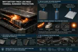
The lid closes the upper boundary of the battery enclosure and often sits in the predicted direction of cell venting. Prismatic cells frequently vent upward, many cylindrical cells vent axially toward the top of the module, and pouch-cell rupture can direct gas toward the cover depending on the cell orientation and support.
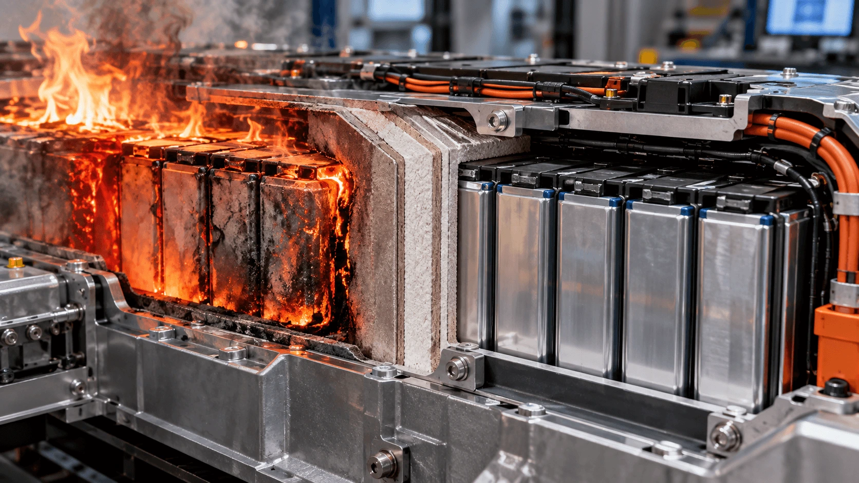
During thermal runaway, the cover may receive a combination of jet flame, high-temperature gas, electrolyte droplets, metal or electrode particles, and intense radiation. The plume can strike one point, spread laterally, reflect from ribs, and enter openings around fasteners, pressure vents, connectors, harnesses, and seal flanges.
Once heated, a metal lid can spread energy far beyond the trigger cell. An aluminum cover is lightweight and conductive, so localized heat can travel rapidly along the panel. Steel has lower thermal conductivity than aluminum but can still transfer heat and remain hot for an extended period. Composite lids can provide lower conductivity but may contain resins or adhesives that soften, delaminate, smoke, or burn.
The lid also separates the battery from the vehicle floor, cabin, cargo space, electronics, or structural adhesives. Protecting it is therefore a pack-level safety function, not merely a cosmetic requirement.
Four Protection Mechanisms of a Mica Insulation Sheet for Battery Pack Lids
The first mechanism is flame separation. Mica provides an inorganic, high-temperature surface that can reduce direct flame contact with the lid and delay burn-through.
The second mechanism is thermal resistance. Mica slows conductive heat flow through its thickness and can reduce the rate at which the cover temperature rises. When greater insulation is required, mica is often combined with a lower-conductivity core such as aerogel.
The third mechanism is erosion and particle protection. A reinforced mica surface can resist hot particles and molten droplets that would damage a thin polymer film or directly strike the cover.
The fourth mechanism is dielectric protection. Mica helps separate high-voltage conductors and conductive ejecta from a metal lid. This is particularly important when vent products contain conductive particles or when busbar insulation is damaged during the event.
A successful design normally uses more than one mechanism. A barrier that resists flame but transfers too much heat may overheat the lid. A low-conductivity layer that erodes under a jet may lose coverage. The mica construction should balance flame, thermal, electrical, mechanical, and manufacturing requirements.
Where a Mica Insulation Sheet for Battery Pack Lids Is Installed
The most direct placement is against the underside of the pack cover. The mica may be bonded to the lid, mechanically retained by clips or ribs, captured between the lid and an inner frame, or installed as a removable fire-protection panel.
A second approach places the barrier on a support structure above the cells, leaving a controlled gap between the barrier and the lid. This can reduce direct conductive contact and allow gas to flow toward a designed exhaust path.
Segmented panels can follow stamped ribs and complex contours more easily than one rigid sheet. Overlaps or shiplap-style joints may be used to avoid line-of-sight flame paths, but the joints must not create excessive thickness, trapped gas pockets, or assembly problems.
Local mica shields may be added above known vent zones, busbar clusters, contactors, service disconnects, or fuse assemblies. However, local protection should be supported by plume mapping because the hot-gas footprint can be much larger than the vent opening.
How Much Lid Coverage Is Required?
The correct coverage is based on the thermal-runaway plume, not only the cell outline. A jet can expand after leaving the vent, strike the lid, spread laterally, and follow ribs or seams. The protected area should include the direct impact zone, expected spread zone, neighboring high-voltage hardware, and potential line-of-sight paths toward lid openings.
A full-area under-lid liner offers broad protection and reduces the risk of missing an unexpected plume direction. It can also add cost, mass, assembly time, and more adhesive area. A zoned design can be lighter and less expensive but requires stronger evidence from testing or simulation.
Coverage should extend around pack vents, pressure-relief devices, service ports, coolant fittings, electrical connectors, and lid bolts without obstructing their function. Clearances and overlaps must preserve the intended gas path and electrical spacing.
When several mica panels are used, the drawing should define overlap width, joint orientation, maximum gap, fastener location, and whether the plume can enter behind the panel.
How Vent Routing Affects Mica Lid Protection
Mica should shield the cover without blocking the cell or pack pressure-relief path. If the barrier traps gas between the cell array and lid, pressure can rise or the jet can be redirected toward a neighboring module.
The design team should map the route from the cell vent to the pack vent. The route must tolerate temperature, pressure, particles, and possible ignition. Mica can line this route, protect corners, and separate the hot stream from sensitive components.
Stand-off features or channels may maintain a controlled flow gap between mica and the lid. Segmented barriers can guide gas toward a relief device, but sharp turns and small openings may increase pressure loss or particle accumulation.
The mica itself is not a pressure-relief device. It is a protective surface within the vent-management architecture. Cell, module, and pack testing should confirm that the barrier does not interfere with vent opening or redirect hazards outside the intended zone.
How Mica Resists Direct Flame and Hot-Gas Jets
A thermal-runaway jet combines heat transfer and mechanical attack. Gas velocity, particles, flame chemistry, distance, angle, and exposure time influence how quickly the barrier erodes or heats through.
Phlogopite-based mica is often selected for severe high-temperature exposure, while muscovite may be suitable where dielectric performance and moderate heat resistance dominate. The binder and reinforcement can be as important as the mineral type.
Glass fabric or other reinforcement can help the sheet remain coherent after the binder changes under heat. A shaped metal or composite deflector may be placed below the mica when the jet is highly concentrated.
Do not use a generic maximum-temperature number as the acceptance criterion. A 1,000°C-class flame claim does not specify heat flux, duration, distance, support, particle impact, or retained electrical performance. Use burner, torch, hot-gas, or cell-vent tests that reproduce the real pack exposure.
How Mica Reduces Radiant Heat to the Pack Lid
Radiation becomes increasingly important as the source temperature rises. Even without direct flame contact, a hot cell, busbar, or plume can rapidly heat the cover through line-of-sight radiation.
A mica sheet interrupts the direct radiation path and absorbs or reflects part of the incident energy, depending on its surface, color, coating, and laminate structure. The cold-side temperature then depends on the mica thickness, thermal conductivity, contact with the lid, air gaps, and any insulating core.
An air gap can add thermal resistance, but it must be controlled so the panel does not sag or contact the lid under pressure, vibration, or heat. Open gaps can also become gas channels.
For high-energy packs, a mica-aerogel or mica-ceramic composite can reduce the backside temperature more effectively than mica alone. The complete stack should be compared under the same heat flux and mounting conditions.
How Mica Protects Against Hot Particles and Conductive Ejecta
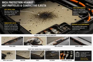
Cell vent products can include metallic particles, electrode fragments, carbonaceous material, and electrolyte droplets. These materials may be hot, mechanically damaging, and electrically conductive.
A mica liner can keep particles away from the lid, lid bolts, busbars, harnesses, and exposed metal surfaces. Reinforced mica is especially valuable when the barrier must tolerate impact without tearing or developing a hole.
Particle accumulation at panel edges, bolt pockets, or ribs can create conductive paths. The design should minimize ledges and unprotected cavities where ejecta can collect.
After testing, inspect not only the central impact area but also the back side, edges, seams, fasteners, and electrical surfaces. A visually intact panel may still allow conductive contamination through a gap.
How Mica Preserves High-Voltage Isolation Near the Lid
Modern EV packs can contain busbars, sense lines, contactors, fuses, service disconnects, and connectors close to the cover. During deformation or thermal runaway, the electrical spacing between these parts and the lid can change.
Mica provides a high-temperature dielectric layer that can remain between energized hardware and a metal cover after ordinary polymer insulation has softened. It can also separate conductive ejecta from grounded metal.
The specification should define dielectric strength, insulation resistance, test voltage, dwell time, leakage current, humidity conditioning, and performance after heat aging or flame exposure.
Creepage and clearance remain geometric properties. Holes, seams, fasteners, adhesive residue, cracked edges, and exposed ribs can shorten the electrical path. The under-lid drawing should include high-voltage keep-out zones and minimum overlaps around conductors.
Mica Lid Protection for Prismatic Cell Packs
Prismatic cells often use a top pressure-relief vent, making the lid a primary receiving surface. The mica liner should be coordinated with vent caps, busbars, sensing harnesses, and top cooling or structural features.
The plume may be narrow near the vent and wider at the lid. A local shield should therefore exceed the vent footprint. For large-format cells, near-full under-lid coverage may be more robust than individual small patches.
Busbar and terminal regions can create additional arc or flame paths. Mica can be integrated with a shaped polycarbonate carrier to maintain electrical coverage around terminal windows and fasteners.
Cell-to-pack designs reduce module walls and can expose a larger continuous lid area. This increases the value of full-system plume mapping and segmented barriers that follow pack ribs without leaving gaps.
Mica Lid Protection for Cylindrical Cell Packs
Many cylindrical cells vent axially toward the top of the module. In a dense array, multiple open channels can direct gas toward the lid, busbar plate, or module cover.
A mica under-lid sheet can protect the broad cover area, while local row barriers, vent manifolds, or busbar shields control the flow before it reaches the lid.
The barrier must not obstruct intended cell venting or normal cooling airflow. Cutouts around busbars and cell holders should preserve dielectric coverage and avoid line-of-sight paths.
For large-format cylindrical cells, sidewall rupture is also possible. Under-lid mica should be combined with perimeter and row protection when the module test identifies radial hazards.
Mica Lid Protection for Pouch Cell Packs
Pouch cells do not always vent through a single engineered opening. Gas can escape through seals or rupture zones, creating a less predictable plume.
Broader under-lid protection may therefore be appropriate. Flexible mica laminates can follow the cover geometry and protect a wide area without placing a rigid layer against the pouch surface.
Tab regions, busbar joints, and polymer frames should be included in the heat and electrical map. Mica can shield the lid while silicone foam or other compliant materials manage cell swelling below.
Testing should include aged cells and realistic mechanical support because pouch-cell swelling can change the distance between the cell and lid over vehicle life.
Muscovite vs Phlogopite for Battery Pack Lids
Muscovite is widely associated with strong dielectric properties and stable electrical-insulation performance. It may be suitable for moderate under-lid heat exposure, busbar zones, and designs where thinness and die-cut quality are priorities.
Phlogopite generally offers higher temperature capability and is often preferred for direct flame, hot-gas, and severe thermal-runaway exposure.
The mineral choice does not determine the finished result by itself. Binder chemistry, mica-paper quality, glass reinforcement, thickness, adhesive, coating, and mounting can change burn-through and post-fire integrity.
A supplier should identify the exact grade and source. Switching mineral type, binder content, or reinforcement after validation should trigger engineering review.
How Thick Should a Mica Insulation Sheet for Battery Pack Lids Be?
There is no universal lid-liner thickness. Thin mica can provide electrical and moderate flame protection; thicker mica can increase burn-through time, stiffness, particle resistance, and thermal resistance.
The correct thickness depends on cell energy, state of charge, vent-to-lid distance, plume angle, lid material, unsupported span, reinforcement, adhesive, available package space, and the required cold-side temperature or burn-through time.
Specify the minimum finished thickness rather than only a nominal value. Pressing, grinding, lamination, adhesive, and local compression can create thinner areas.
Prototype at least two thicknesses or stacks. Compare backside temperature, damaged area, mass, stiffness, assembly time, warpage, cost, and the ability to follow the lid geometry.
How Binder and Reinforcement Affect Lid Protection
Commercial mica sheets use a binder to hold mica paper or flakes together. Silicone binders are common in high-temperature flexible products; epoxy systems can create rigid boards.
Higher binder content can improve toughness and die-cut yield but adds organic material that can smoke, char, or lose strength. Too little binder can cause dust and delamination.
Glass fabric, glass fiber, or other reinforcement can keep the mica layer coherent after heat exposure and improve resistance to particle impact. Reinforcement also changes stiffness, thickness, heat transfer, and edge quality.
The production bill of materials should control mica type, binder, reinforcement, thickness, adhesive, and source. The finished laminate requires its own validation.
Should the Mica Lid Liner Be Adhesive-Backed?
Adhesive backing can simplify placement on large covers and prevent panel movement during lid handling and pack assembly.
Full-face adhesive maximizes initial contact but adds a continuous polymer layer and can increase heat transfer into the lid. It may also create smoke, shrinkage, or loss of attachment during severe heat.
Selective adhesive zones can hold the panel while preserving air gaps or reducing thermal bridging. Perimeter adhesive, central registration points, and mechanically captured edges are common design concepts.
The adhesive should be evaluated on the actual lid finish. Bare aluminum, anodized aluminum, e-coated steel, painted metal, and composite surfaces have different surface energies and aging behavior.
The abuse-event requirement should state whether the adhesive must retain full bond strength, merely hold the panel until mechanical retention engages, or allow controlled charring while the mica remains captured.
Mechanical Retention, Fasteners, and Lid Ribs
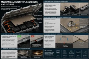
Large under-lid panels may need clips, tabs, ribs, washers, frames, or mechanical capture because adhesive alone may not retain the barrier after prolonged heat.
Fastener holes create stress concentrations and electrical openings. Use adequate hole-to-edge distance, reinforcement, insulating washers, and smooth hardware surfaces.
Stamped lid ribs can support the mica and reduce sagging, but they also create contact lines that conduct heat through the barrier. The panel should not be crushed against sharp rib edges.
Segment joints should be oriented away from direct plume paths where possible. Overlaps need enough width to prevent flame penetration without creating excessive local thickness or assembly interference.
Vibration and thermal cycling can loosen mechanically retained panels. Test the actual lid assembly, not only the mica sheet.
Mica and Aerogel for Battery Pack Lid Protection
Mica is strong against flame, particles, and electrical faults, while aerogel provides much lower thermal conductivity. A composite can combine a mica hot-face with an aerogel insulating core.
This approach is useful when the lid must remain below a defined backside temperature or when the pack has limited clearance to the vehicle structure.
Aerogel is compression-sensitive and can release particles if not encapsulated. The mica facing and edge construction should protect it from the plume without creating a rigid thermal bridge around the perimeter.
Full-face adhesive between layers can change thermal resistance. Test the exact laminate with its installed pressure, air gap, joints, and lid substrate.
Mica and Flame-Retardant Polycarbonate for Lid Liners
Flame-retardant polycarbonate can provide a clean, puncture-resistant, self-supporting carrier for a complex under-lid part. It can include locating holes, formed tabs, identification, and mounting features.
Mica should normally face the expected high-temperature side when direct flame or particles are possible. PC can sit toward the lid or protected side to provide structure, depending on the test result.
A UL 94 V-0 classification for PC is useful for polymer flammability screening, but it does not prove resistance to a battery vent jet or pack-level thermal propagation.
The laminate must control differential thermal expansion, curl, bubbles, adhesive registration, and edge lift. The complete construction should be tested after thermal cycling and humidity.
Mica and Silicone Foam Near Battery Pack Lids
Silicone foam can provide sealing, vibration isolation, gap management, and controlled stand-off between the mica liner and lid structure.
A foam frame can support a mica panel around ribs or maintain a defined air gap. However, the foam should not block pack vents or create a closed pressure pocket.
Direct flame exposure may require a specially qualified flame-resistant silicone construction. Standard cushioning foam should not be assumed to provide the same high-temperature protection as mica.
Compression set, outgassing, adhesive compatibility, smoke, and post-fire support should be evaluated. The mica should remain positioned even if the foam softens or chars.
How Lid Material Changes the Mica Design
Aluminum lids are lightweight and thermally conductive. Mica or a mica-aerogel stack can reduce rapid heat spreading and protect adhesive joints, seals, and vehicle-side structures.
Steel lids can provide strong mechanical and fire resistance but still need electrical isolation and backside-temperature control. Weight and corrosion coatings influence attachment design.
Composite lids may offer lower thermal conductivity and structural integration, but their resin system, fibers, inserts, and bonding adhesives can have different fire behavior. Mica can protect the composite surface from direct flame and particles.
Plastic local covers and service lids may need mica-PC or mica-film laminates that combine shape, dielectric coverage, and a high-temperature face.
The under-lid test must use the actual substrate, thickness, coating, rib pattern, seals, adhesives, and unsupported spans.
Thermal Bridges That Bypass the Mica Lid Liner
Lid bolts, metal ribs, brackets, busbar supports, connector housings, cooling manifolds, and frame contacts can carry heat around the mica panel.
A full-area sheet may still provide limited protection if a steel bolt connects the hot inner structure directly to the lid. Insulating washers, stand-offs, slots, lower-conductivity supports, or local shields may be needed.
Panel edges can become parallel heat paths when a mica-PC laminate or adhesive seam contacts both the hot structure and lid. Joint design should preserve thermal separation.
Thermocouples and heat-flux sensors should be placed on likely bypasses during testing. Measuring only the center of the lid can miss the real maximum temperature.
DFM for a Mica Insulation Sheet for Battery Pack Lids
Under-lid liners are often among the largest and most complex insulation parts in the pack. They may include ribs, bolt holes, connector openings, vent clearances, service ports, overlaps, adhesive zones, and orientation features.
A large rigid mica sheet can crack or warp during handling. Segmentation, reinforcement, controlled radii, adequate webs, and protective packaging may improve yield and assembly.
Flatbed die cutting, rotary die cutting, CNC processing, or other methods may be selected according to material, thickness, geometry, and production volume. Tool sharpness, support, dust control, and edge inspection are critical.
The drawing should define datums, overall dimensions, flatness, thickness, edge chipping and delamination limits, hole tolerance, overlap, adhesive registration, liner split, pull tabs, orientation, labels, and packaging.
Prototype the complete lid assembly. A part that lies flat on a table may lift over stamped ribs, interfere with bolts, or crack during liner removal.
How to Validate Mica Lid Protection
Level 1 validates raw material and laminate properties: thickness, areal mass, dielectric strength, insulation resistance, high-temperature shrinkage, flame response, strength, moisture, and chemical compatibility.
Level 2 validates the converted liner: dimensions, flatness, edge cracks, holes, overlaps, adhesive peel, liner release, particle contamination, and packaging.
Level 3 uses representative lid coupons with the actual substrate, adhesive, air gap, ribs, fasteners, and support. Test heat flux, flame, hot gas, particles, burn-through, and backside temperature.
Level 4 uses a representative module or cell array below the lid. Record plume direction, lid temperatures, barrier damage, gas flow, electrical isolation, pressure, and ignition outside the intended zone.
Level 5 validates the complete pack or vehicle. Confirm warning, controlled venting, external hazard criteria, structural response, electrical isolation, and post-event condition. A mica data sheet alone cannot establish system compliance.
What UN Regulation No. 100 Means for Lid Barriers
UN Regulation No. 100 evaluates the safety of the rechargeable energy storage system and vehicle rather than prescribing one specific lid material.
The 05 series of amendments entered into force in September 2025 and strengthens the system approach to thermal propagation. Transitional dates apply to new and existing type approvals. This regulatory direction increases the value of validated barriers that support warning time, controlled venting, and protection from external hazards.
A mica lid liner may contribute to the pack result, but compliance depends on the cell, enclosure, venting, sensing, electrical design, mounting, and complete test procedure.
Supplier documents should therefore describe material and part performance accurately and avoid claiming that a raw mica sheet is independently ‘UN R100 certifies
Common Battery Pack Lid Protection Mistakes
The first mistake is protecting only the exact area above a cell vent while ignoring plume expansion and lateral spread across the lid.
The second mistake is blocking the intended gas path with a full-area bonded liner that creates pressure pockets.
The third mistake is using the mica mineral temperature as the rating for a laminate containing lower-temperature binder, film, foam, or adhesive.
The fourth mistake is relying on UL 94 V-0 as proof of jet-flame or thermal-propagation performance.
The fifth mistake is ignoring fasteners, ribs, seams, electrical openings, and metal heat bridges.
The sixth mistake is testing a small flat coupon and applying the result to a large stamped lid with unsupported spans and complex attachment.
The seventh mistake is changing the mica grade, reinforcement, adhesive, thickness, or converter after pack validation without technical review.
Industry Insight: Under-Lid Barriers Are Becoming Engineered Assemblies
The industry is moving from simple flat mica boards toward segmented under-lid systems, shaped vent shields, mica-aerogel composites, mica-PC carriers, coated fabrics, ablative layers, and integrated sealing structures.
This shift is driven by larger cells, higher pack integration, cell-to-pack designs, 800 V systems, fast charging, and reduced distance between the cell array and vehicle structure.
Buyers increasingly request application data: backside-temperature curves, burn-through time, particle resistance, post-fire dielectric integrity, pressure behavior, and performance on the actual lid substrate.
For a precision converter, the commercial opportunity is not only supplying mica sheet. It is turning the material into a clean, flat, traceable, assembly-ready liner that fits complex ribs and openings and can be revised quickly after pack testing.
How to Specify a Mica Insulation Sheet for Battery Pack Lids
Identify the cell chemistry, format, capacity, state of charge, vent direction, cell-to-lid distance, module layout, busbar geometry, pack venting, lid material, rib pattern, seals, fasteners, and protected vehicle-side components.
Specify mica type, binder, reinforcement, rigid or flexible construction, nominal and minimum thickness, areal mass, dielectric strength, insulation resistance, flame or heat-flux exposure, backside-temperature limit, burn-through criterion, and approved supplier.
The drawing should define coverage, panel segmentation, overlaps, vent and connector keep-outs, holes, minimum webs, radii, adhesive zones, mechanical retention, air gaps, flatness, edge quality, orientation, labeling, and packaging.
Add aging tests, sampling, PPAP level, lot traceability, and change-control requirements. The specification must cover the complete production laminate and mounting method.
RFQ Checklist for Mica Battery Pack Lid Liners
Provide the lid CAD, cell and module layout, vent locations, cell-to-lid distance, pack voltage, protected components, expected plume direction, pack relief path, lid material, surface coating, and available thickness.
State the required flame, hot-gas, particle, heat-flux, backside-temperature, burn-through, electrical, vibration, humidity, and pack-level test criteria.
Define whether the desired construction is mica alone, reinforced mica, mica plus aerogel, mica plus polycarbonate, mica plus silicone foam, adhesive-backed, mechanically retained, or open for supplier recommendation.
Include prototype quantity, annual volume, tooling strategy, PPAP level, packaging, production timing, and any current burn-through, lid-temperature, delamination, warpage, adhesion, or assembly issue.
How Boost Insulation Supports Battery Pack Lid Protection
Boost Insulation’s current public website describes an IATF 16949- and ISO 9001-certified China manufacturer focused on EV battery insulation and precision die cutting. Its public capabilities include early DFM support, in-house tooling, controlled-environment lamination and die cutting, 48-hour custom samples, APQP and PPAP support, and lot-to-lot traceability.
The company promotes mica, flame-retardant polycarbonate, aerogel, silicone sheets and foams, thermal materials, films, adhesives, CNC processing, slitting, lamination, and rotary die cutting. Its website also states suitable components can be produced with dimensional tolerances as tight as ±0.05 mm.
For a lid project, engineering support can include plume-coverage review, mica-grade selection, panel segmentation, mica-aerogel and mica-PC lamination, adhesive zoning, mechanical-retention features, edge DFM, prototype tooling, dimensional inspection, voltage testing, and validation-sample preparation.
A useful inquiry should include the lid and cell-layout CAD, vent path, voltage, thickness envelope, lid substrate, test target, annual volume, and PPAP requirements.
| Need a custom under-lid mica barrier or multilayer pack-cover liner?
Send Boost Insulation the battery-pack lid CAD and cell-vent layout together with the pack voltage, cell-to-lid distance, plume or heat-flux test, backside-temperature target, lid material, attachment method, annual volume, and PPAP requirements. The engineering team can review mica, aerogel, flame-retardant PC, silicone foam, adhesives, panel segmentation, and precision die-cut options. Visit boostinsulation.com to upload a drawing or request a quote |
Frequently Asked Questions
Why is mica installed under an EV battery-pack lid?
It protects the cover from flame, hot gas, particles, radiant heat, and conductive ejecta while maintaining a high-temperature dielectric barrier around busbars and metal structures.
Should mica cover the entire battery-pack lid?
Full-area coverage provides robust protection, but zoned coverage can reduce mass and cost when plume behavior is well understood. The final coverage should be based on vent and heat-path testing.
Can mica stop the pack lid from heating?
Mica delays heat transfer but does not eliminate it. Backside temperature depends on thickness, contact, lid material, heat flux, duration, air gaps, and whether aerogel or another insulating layer is added.
Is mica better than aerogel under the lid?
Mica is stronger against direct flame, particles, and electrical faults. Aerogel provides lower thermal conductivity. A mica hot-face with aerogel behind it is often effective for severe exposure.
Can mica be bonded directly to an aluminum lid?
Yes, but the adhesive must be compatible with the aluminum finish, heat, humidity, vibration, and fire scenario. Mechanical capture or selective adhesive may improve abuse-event retention.
How thick should an under-lid mica sheet be?
There is no universal thickness. Select the minimum production thickness that passes the required burn-through, backside-temperature, dielectric, mechanical, and pack tests with margin.
Does UL 94 V-0 prove that the lid liner stops thermal runaway?
No. UL 94 is a small-scale material flammability classification. It does not reproduce battery vent jets, particles, pressure, pack geometry, or thermal propagation.
What files are needed for a custom lid liner?
Provide the lid CAD, cell and vent layout, pack voltage, plume or heat-flux test, lid material, attachment method, thickness envelope, volume, and PPAP requirements.
Technical References
- Boost Insulation. EV battery insulation, precision die cutting, DFM, 48-hour prototyping, IATF 16949, ISO 9001, APQP, PPAP, and traceability capabilities. Source
- Electrolock. Thermal Runaway Protection in EV Batteries: The Role of Mica, including battery-pack lid applications and rigid or flexible mica constructions. Source
- Boyd. EV Battery Protection Materials Comparison: mica use under battery lids, covers, and separators. Source
- E-Mobility Engineering. Battery Thermal Barriers in E-Mobility: mica flame, thermal, dielectric, and high-temperature barrier functions. Source
- Nambisan, P. et al. Characterization of Commercial Thermal Barrier Materials to Mitigate Thermal Runaway Propagation in Lithium-Ion Battery Modules. Journal of Energy Storage, 2023. Source
- Kim, H. S. et al. Flame-Retardant Battery Pack Case Design for Delaying Thermal Runaway Propagation. Materials, 2025. Source
- UL Solutions. Combustion Tests for Plastics and the application limits of UL 94 classifications. Source
- UNECE. UN Regulation No. 100, Revision 3. Source
- UNECE. Proposal and adopted 05 series framework for improved thermal-propagation requirements under UN Regulation No. 100. Source
- Global Auto Regs. UN Regulation No. 100 modification history, including entry into force of the 05 series on 26 September 2025. Source
Related Posts:
Why Does EV Battery Insulation Need UL94 V-0?
How Does a Mica Insulation Sheet Compare With FR4 Boards?
How to Choose EV Battery Cell Insulation Pads?
Where Should Thermal Barriers Be Placed Between Cells?
Why Does Mica Insulation Survive High Heat in EV Batteries?
How Does Cell-to-Cell Thermal Barrier Improve ESS Safety?
 betty wong
