
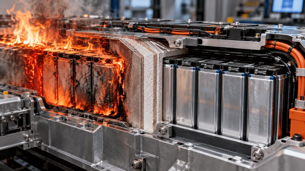
Why Does Mica Insulation Survive High Heat in EV Batteries?
Table of Contents
A mica sheet may be described as highly heat resistant—but what actually happens when the finished insulation part faces intense radiant heat, direct flame, a vent jet, or conductive heating from a nearby battery component? The answer matters because the material that survives on a datasheet is not always the same as the assembly that survives in a pack. In practice, mica mineral, binder, reinforcement, adhesive, laminate geometry, mounting method, and exposure profile all contribute to the final result.
Mica insulation survives high heat primarily because its inorganic, layered silicate structure does not soften and melt like many thermoplastic insulation films. For mica heat resistance for EV batteries, however, the decisive question is not whether the mineral survives, but whether the complete component remains useful. Mica type, paper structure, binder chemistry, reinforcement, thickness, adhesive, lamination, heat flux, exposure duration, and mechanical support can all change post-exposure integrity. Engineers should therefore evaluate the finished die-cut part—then the installed assembly—rather than assign a raw-mineral temperature capability to the entire insulation system.
Key Takeaways
- Mica mineral heat resistance is not the same as finished mica component heat resistance.
- Heat resistance describes survival under temperature; thermal insulation describes resistance to heat transfer. They are related but not interchangeable.
- Binder, glass reinforcement, adhesive, films, lamination and mounting features can become the limiting elements before the mica mineral itself.
- Direct flame, radiant heat, conductive heating and hot-gas jets create different thermal and mechanical loads, so one test cannot represent every battery location.
- The most useful severe-heat metric is often retained function after exposure: continuity, position, attachment, electrical isolation and absence of critical damage.
- Qualification should progress from raw material to finished component, installed assembly, and finally module or pack validation.
What Does “Heat Resistant” Mean for EV Battery Insulation?
Heat resistance is not one temperature number. In an EV battery, a material may see years of moderate operating temperature, repeated thermal cycling, a short high-temperature excursion, or a highly localized thermal-runaway event. Each case imposes a different combination of temperature, time, heat flux and mechanical stress. A useful specification therefore separates continuous operating conditions from abnormal-event exposure and identifies what function must remain afterward.
For a severe event, peak temperature alone can be misleading. A thin flame plume with very high local heat flux may damage a surface faster than a larger region held at a lower temperature. Conversely, a material may tolerate a short exposure that would be unacceptable as a continuous-use condition. The test setup—distance to the source, sample support, airflow, pressure, exposed area and dwell time—can materially change the result.
Battery insulation engineers should define the exposure in physical terms: direct flame or no flame; radiant heating; conductive contact to a hot surface; hot gas or vent ejecta; exposure duration; expected heat flux where known; and whether the required output is no burn-through, a maximum cold-side temperature, retained dielectric performance, retained attachment, or some combination. A single generic “maximum temperature” rating cannot communicate all of these conditions.
Industry Insight 1 — Post-exposure function is becoming more useful than a single maximum-temperature claim. For engineers and buyers, this means RFQs should specify the required retained function and exposure profile, not just a temperature number.
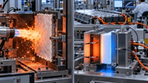
Heat Resistance vs Thermal Insulation: What Is the Difference?
Heat resistance is the ability of a material or component to resist unacceptable softening, decomposition, shrinkage, cracking, loss of cohesion or functional failure at elevated temperature. Thermal insulation is the ability to reduce heat transfer from the hot side to the cold side. A material can be very heat resistant yet not provide the highest thermal resistance per millimeter.
This distinction is critical when mica is compared with aerogel. Mica is frequently selected where the barrier must remain physically present, electrically insulating and resistant to flame or hot-particle attack. Aerogel is frequently selected where very low heat transfer through a thin gap is the dominant need. The engineering decision should therefore be based on the failure mode and required function, not on which material has the more impressive temperature statement.
For buyers, the practical implication is that “high-temperature” and “high thermal insulation” should be separate specification lines. If the application needs both, a multilayer construction may be appropriate—but the stack must be validated as a stack because adhesive, compression, seams and edge bridges can change the heat path.
Why Is the Mica Mineral Itself Heat Resistant?
Mica is an inorganic silicate mineral with a layered crystal structure. Unlike many thermoplastics used in battery insulation, the mineral does not rely on polymer-chain integrity to maintain its basic solid form. That is one reason mica can remain present when nearby polymer films shrink, soften, melt or decompose under severe heat.
This does not mean all mica grades behave identically. Muscovite, phlogopite and synthetic mica differ in chemistry and in the products made from them. More importantly, commercial EV insulation is rarely a piece of pure mineral. It is usually mica paper or reconstituted mica combined with a binder, reinforcement and sometimes additional films or adhesive. Established manufacturers publish materially different constructions and ratings, illustrating why the raw mineral cannot be used as a universal finished-part specification.
The design value of mica in a battery barrier is therefore its combination of inorganic thermal stability, dielectric behavior and ability to be converted into sheets, tapes or reinforced laminates. The exact thermal limit remains grade-dependent, thickness-dependent, construction-dependent and test-method-dependent.
Muscovite vs Phlogopite: Does Mica Type Matter?
Yes. Muscovite and phlogopite are different mica minerals, and commercial sheet suppliers commonly position them differently. Phlogopite grades are often selected when higher-temperature capability is the primary requirement, while muscovite grades can offer attractive electrical or mechanical properties for other applications. This is a selection trade-off, not a universal ranking.
For an EV battery engineer, the mineral name should not be the final specification. The required question is: which specific sheet construction—mineral type, mica content, binder system, reinforcement and thickness—has data that match the exposure and function? Two sheets labeled “phlogopite mica” can behave differently if their binder, reinforcement, density or lamination architecture differs.
Selection should also consider converting behavior. A grade that survives the intended heat exposure but cracks around narrow webs, cannot hold the required flatness, or becomes too fragile after punching may be a poor finished-component choice. Thermal capability and manufacturability have to converge in the same part.
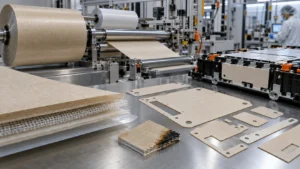
How Does Mica Paper Become a Battery Insulation Sheet?
The path from mineral to installed EV component matters because each processing step adds a new variable. Natural or processed mica is converted into mica paper; the paper is consolidated with a binder; reinforcement may be added; the sheet may be laminated to films, foam, aerogel or pressure-sensitive adhesive; and the resulting stack is die-cut into the final geometry. The finished component then experiences handling, liner removal, alignment, fastening, compression and vehicle-life aging before any abnormal thermal event occurs.
Mica paper provides the inorganic high-temperature backbone, but it needs sufficient cohesion for handling and conversion. Binder chemistry helps hold the structure together and influences stiffness, flexibility and thermal aging. Glass cloth or glass-fiber reinforcement can add tensile support and improve handling. Adhesives and carrier films can make assembly easier but introduce organic layers whose thermal behavior may be very different from the mica.
This is why raw mineral properties cannot simply be copied into a drawing note for a finished laminate. A better specification names the target grade or approved construction, required thickness, reinforcement, adhesive or lamination structure, the expected exposure, and the function that must remain after the exposure.
Why Does the Binder Matter at High Temperature?
The binder is the structural partner that turns loose or reconstituted mica paper into a practical sheet. Silicone-based systems are common in high-temperature mica products, while other resin systems are used where different mechanical, processing or electrical performance is required. The binder influences sheet cohesion, stiffness, dimensional stability, moisture response and how the part behaves during cutting and handling.
Under severe heat, an organic binder can begin to degrade before the mica mineral loses its underlying thermal stability. Depending on chemistry and exposure, that degradation can reduce cohesion, change flexibility, generate char or volatiles, or make the remaining mica structure more fragile. A sample may therefore still look “present” while its mechanical condition has changed significantly.
For engineers, the key question is not simply whether the binder survives unchanged. It is whether the post-exposure construction still performs the required barrier function. Some applications may tolerate binder loss if the reinforced mica remains mechanically captured and electrically isolating; others may require dimensional stability, adhesive retention or crack resistance that makes binder performance a critical design variable.
Why Is Glass Fiber Reinforcement Used?
Glass-fiber reinforcement can improve mechanical support, handling strength, dimensional stability and tear resistance. This is especially useful for large sheets, narrow die-cut webs, parts with multiple holes, or flexible barriers that must be installed without cracking. Established mica-product manufacturers offer constructions with glass cloth or glass fleece precisely because the mica layer and the reinforcement can serve different functions.
The distinction becomes more important after heat exposure. The mica fraction may remain thermally stable while organic constituents lose strength. Reinforcement can help the residual barrier remain continuous and in position rather than becoming a loose or cracked layer. It can also improve the manufacturability of thin components before they ever reach the pack.
Reinforcement is not automatically beneficial in every design. It can change thickness, stiffness, drape, edge quality, thermal path and cost. The engineering choice should be tied to the geometry, mounting method and post-exposure function—not to a generic assumption that more layers are always better.
Can the Adhesive Fail Before the Mica?
Yes. Depending on the adhesive system and the exposure, the adhesive can become the limiting layer before the mica. Pressure-sensitive adhesives are selected for assembly efficiency, initial tack, peel performance, liner behavior and compatibility with the substrate—not solely for extreme-temperature survival. Under severe heat they may soften, lose bond, shrink, outgas, char or allow edge lift and delamination.
This creates a common specification error: assigning the temperature capability of the mica laminate to an adhesive-backed finished part. The construction may still contain thermally stable mica while the part has moved away from the protected surface or opened a seam. If the barrier must stay attached through an abnormal event, adhesive performance and mechanical capture need to be considered together.
Adhesive coverage also changes heat flow. Full-face bonding can increase contact area and reduce an insulating air gap; selective adhesive can simplify removal or limit heat bridging but may create local stress or unsupported regions. The adhesive pattern, thickness, release liner and assembly pressure therefore belong in the thermal design review, not only in the purchasing specification.
Industry Insight 2 — Adhesive and lamination can become the limiting layers in a high-temperature mica component. Buyers should qualify the actual adhesive-backed laminate, not approve mica and adhesive as unrelated line items.
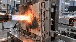
What Happens to Mica During Severe Heat Exposure?
A useful way to think about severe-heat behavior is as a sequence rather than a single pass/fail temperature. During normal operation, all layers should remain within their intended environmental window. As temperature rises, polymeric layers and adhesives may soften or change modulus. At higher exposure, binder and adhesive chemistry may degrade, and local delamination or shrinkage can begin. Under direct flame or a concentrated vent jet, the surface may also experience erosion, particle impact and large thermal gradients.
As organic constituents degrade, the remaining inorganic mica structure may continue to occupy the barrier location, but its mechanical state can change. It may become more brittle, less cohesive or more dependent on reinforcement and mechanical support. Carbonized residues from organic materials can also alter surface electrical behavior, especially if conductive contamination is present.
The correct conclusion is therefore conditional: mica can retain useful barrier structure under severe heat, but the retained function depends on the specific construction and exposure. Engineers should document what happens after the event—not only whether the mica mineral is still visible.
Direct Flame vs Radiant Heat vs Hot Gas vs Conductive Heat
Different heat sources attack insulation differently. Direct flame combines intense convective and radiative heating with a localized flame front. Radiant heating can load a larger surface without direct contact, making emissivity, view factor and exposure time important. Conductive heating transfers energy through contact with a hot cell case, busbar, enclosure or adjacent layer. A hot-gas vent jet can combine convection, flame, pressure, erosion, particles and chemically active ejecta.
Because the mechanisms differ, test outcomes are not directly interchangeable. A material that performs well in a steady radiant panel test may respond differently to a high-velocity vent plume. A thick sheet may resist burn-through under flame but still conduct enough heat to exceed a cold-side limit. An adhesive may survive conductive heating on a supported coupon yet release when a gas jet attacks the edge.
The engineering insight is to match the test to the location. Under-lid barriers should reflect the expected vent direction and plume footprint. Cell-to-cell barriers should consider contact conduction, compression and propagation. Local shields around terminals or busbars may need electrical isolation after heat as much as cold-side thermal performance.
Industry Insight 3 — Thermal-runaway protection is increasingly location-specific. For engineers, this means selecting test methods around the dominant heat-transfer mechanism and vent path instead of using one generic flame test for every barrier.
Why Do Thickness and Layer Construction Matter?
Thickness affects more than one variable at once. A thicker mica barrier can increase the heat path, improve burn-through margin and provide greater mechanical section, but it also consumes package space, adds mass, changes stiffness and can complicate forming or assembly. In tightly packaged battery systems, those trade-offs can be decisive.
Layer construction can be equally important. A thin mica facing over a lower-conductivity core may address flame erosion and thermal resistance differently from a monolithic mica plate. A glass-reinforced flexible mica sheet may survive handling better than an unreinforced thin sheet. A carrier film may improve assembly but become the first layer to shrink during a fault.
Thicker is therefore not automatically better. The correct design uses the minimum architecture that meets the thermal, electrical, mechanical and manufacturing requirements with adequate margin, then verifies the finished stack under representative exposure and mounting conditions.
Industry Insight 4 — Higher energy density reduces the insulation space available. The design response is increasingly architectural: combine functions deliberately rather than adding thickness without understanding the heat path.
What Does “Post-Exposure Integrity” Mean?
Post-exposure integrity means evaluating whether the insulation still performs the functions that matter after severe heat—not whether it merely avoided disappearing. For a battery barrier, the relevant questions may include whether the part remains in position, remains physically continuous, avoids critical cracks, stays attached, prevents direct metal-to-metal contact and retains adequate electrical isolation.
Visual inspection is useful but insufficient. A charred adhesive line may look acceptable while bond strength has collapsed. A mica panel may remain intact but have opened a gap around a fastener. A surface may appear continuous yet carry conductive residue. Conversely, a discolored or embrittled component may still satisfy the required emergency function if it remains correctly located and electrically isolating for the duration of the event.
This shifts the design conversation from “Did the material survive?” to “Which functions survived, for how long, under what boundary conditions?” That is a more defensible basis for engineering decisions and supplier qualification.
Does Mica Remain Electrically Insulating After High Heat?
It can, but it should not be assumed. Post-exposure electrical behavior depends on mica grade, binder degradation, cracking, carbonized organic material, moisture, conductive debris, geometry, electrode spacing and the exact test method. Mica’s inorganic nature is advantageous, but the finished component can accumulate new electrical weak points during an abnormal event.
If high-voltage isolation must remain after heat exposure, the validation plan should include dielectric withstand or insulation-resistance testing on the finished component or assembly after the defined thermal conditioning. The acceptance criterion should be tied to the system requirement rather than to a raw-sheet datasheet value.
This is also why thermal and electrical specifications should be linked. A part that remains physically present but opens a conductive path around an edge, hole or charred adhesive region has not retained the intended insulation function.
Why Finished-Part Validation Matters More Than Datasheet Temperature
A raw material datasheet describes a controlled specimen, not a converted battery part. Die cutting introduces edges, narrow webs, holes and internal corners. Lamination introduces adhesive thickness and registration. Installation introduces pressure, curvature, fasteners, metal burrs, gaps and tolerance stack-up. Vehicle life adds humidity, vibration and thermal cycling. A severe event adds nonuniform heat, flame, vent flow and mechanical movement.
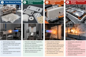
That chain explains why qualification should progress through four levels: raw material, finished component, installed assembly, and module or pack. Each level answers a different question. Raw material testing screens candidate constructions. Finished-component testing checks the real thickness, cut geometry, laminate and adhesive. Assembly testing reveals mounting, edge and contact effects. Pack-level testing addresses the actual thermal event and system interactions.
The engineering objective is not to replace material datasheets; it is to prevent them from being treated as evidence for a question they were not designed to answer.
Industry Insight 5 — Precision converting is moving upstream into insulation engineering. Early DFM can identify narrow webs, edge-lift risks, unsupported areas and laminate-registration issues before thermal validation locks the geometry.
Heat-Resistance Factors in a Finished Mica Insulation Component
| Component | Primary Function | High-Temperature Concern | Possible Failure Mode | Engineering Consideration |
| Mica mineral | High-temperature dielectric backbone | Grade-specific thermal behavior | Loss of required function if wrong grade is selected | Specify mineral/grade only together with finished construction and test evidence. |
| Binder | Holds mica paper structure together | Organic degradation, cohesion loss | Embrittlement, powdering, loss of handling strength | Review binder chemistry and post-exposure mechanical condition. |
| Glass reinforcement | Mechanical support and dimensional stability | Heat-induced strength change or interface damage | Tearing, cracking, loss of support | Use where geometry or post-event continuity requires reinforcement. |
| Adhesive | Assembly and retention | Softening, decomposition, bond loss | Edge lift, delamination, part movement | Do not assign mica temperature capability to the adhesive. |
| Polymer film | Carrier, surface protection, assembly aid | Shrinkage, melting, carbonization | Gaps, exposed edges, conductive char | Validate the actual film/laminate if it remains in the final part. |
| Die-cut edge | Defines barrier coverage | Flame/jet edge attack, cracking | Local burn-through or exposed substrate | Control edge quality, corner radii, narrow webs and burr interfaces. |
| Mounting feature | Locates or fastens the part | Local heat bridge, stress concentration | Gap opening, cracking, metal contact | Review holes, fasteners, clips, compression and tolerance stack-up. |
| Finished laminate | Delivers combined thermal/electrical/mechanical function | Different layers degrade at different rates | Loss of one critical function despite mica survival | Validate the complete laminate under representative exposure and mounting. |
Common Mistakes When Specifying High-Temperature Mica Insulation
- Selecting by a single maximum-temperature number.
- Treating mica mineral capability as the rating of the finished laminate.
- Ignoring binder chemistry and binder loss.
- Assuming adhesive has the same severe-heat capability as the mica layer.
- Confusing heat resistance with low thermal conductivity.
- Ignoring exposure duration and heat flux.
- Treating flame, radiation, conduction and hot-gas exposure as equivalent.
- Ignoring post-exposure electrical performance.
- Validating only raw sheet coupons rather than production-intent parts.
- Assuming thicker mica is automatically better.
- Ignoring edge geometry, holes, fasteners, narrow webs and laminate registration.
- Using a small-scale flame classification as evidence of complete thermal-runaway performance.
How Precision Die Cutting Affects High-Temperature Performance
Precision converting does not change the fundamental chemistry of mica, but it can determine whether the designed thermal barrier remains intact and correctly positioned. A CAD file may specify excellent material, yet narrow bridges, sharp internal corners, poorly supported holes or aggressive adhesive patterns can introduce damage before the part reaches validation.
Edge cracking and delamination matter because severe heat often attacks discontinuities first. A vent plume can exploit an exposed edge, and a fastener can concentrate stress near a hole. Registration error in a multilayer stack can expose a carrier film or adhesive line to the hot side. Cleanliness also matters when the same component has an electrical-insulation role.
Early DFM should therefore review minimum web width, corner radii, hole-to-edge distance, expected bending, adhesive keep-out zones, release-liner strategy, lamination sequence, dimensional inspection and packaging. The goal is not simply to make the part cuttable; it is to preserve the thermal and electrical architecture represented by the drawing.
How Should Engineers Validate Mica for Severe Heat?
1. Raw Material Testing
- Thermal aging or thermal endurance appropriate to the grade
- Relevant flame or heat-exposure screening
- Thickness, density and construction verification
- Electrical properties where required by the application
2. Finished Component Testing
- Production-intent die-cut geometry and minimum thickness
- Adhesion and delamination behavior
- Dimensional change after heat
- Edge condition and crack inspection
- Dielectric testing before and after defined thermal exposure
3. Assembly-Level Testing
- Actual substrate, fasteners, compression and air gaps
- Thermal cycling and vibration before severe-heat testing where relevant
- Representative flame, radiant, conductive or hot-gas load
- Part displacement, seam opening and mounting retention
4. Module / Pack-Level Testing
- Representative cells and vent direction
- Installed stack-up and real enclosure geometry
- System-level temperature, propagation and electrical objectives
- Post-event inspection and electrical verification against the project acceptance criteria
No single test proves that a battery pack is safe. The validation plan should be derived from the battery architecture, applicable regulatory and OEM requirements, the identified failure modes, and the functions assigned to the insulation component.
Engineering Checklist for High-Temperature Mica Insulation
- Application location and protected surface
- Normal operating temperature
- Peak temperature during expected transients
- Abnormal-event temperature or source condition
- Exposure duration
- Heat source and direction
- Heat flux, if known
- Direct flame exposure
- Radiant heat exposure
- Hot-gas or vent-jet exposure
- Required finished thickness and minimum allowable thickness
- Available installation space
- Mica type / approved grade
- Binder system
- Reinforcement requirement
- Adhesive or lamination requirement
- Electrical insulation requirement
- Mechanical load and compression
- Vibration and thermal cycling environment
- Humidity / contamination environment
- Required post-exposure function
- Validation method and acceptance criteria
What to Send With a High-Temperature Mica Insulation RFQ
- PDF, DXF and/or STEP drawing
- Application location in the cell, module or pack
- Battery cell / module / pack architecture
- Target mica grade, if already selected
- Nominal and minimum thickness
- Part dimensions and dimensional tolerances
- Expected heat source and exposure direction
- Normal operating temperature
- Peak / fault exposure condition
- Expected exposure duration
- Direct-flame, radiant or hot-gas requirement
- Adhesive and liner requirement
- Lamination or multilayer stack requirement
- Electrical insulation requirement
- Prototype quantity
- Estimated annual volume
- Validation requirements
- PPAP or automotive quality-document requirements
- Packaging, cleanliness and traceability requirements
From Mica Sheet to Production-Ready Battery Insulation Component
For a real EV program, the sourcing decision is rarely just “buy mica sheet.” The useful deliverable is an assembly-ready insulation component whose material stack, geometry, adhesive, liner, dimensional controls and packaging are compatible with the battery build process. Boost Insulation’s website positions the company around EV battery insulation, DFM, precision die cutting, lamination, adhesive integration, prototyping and production manufacturing rather than raw material supply alone.
That manufacturing role is especially relevant for high-temperature parts because the converting details can determine whether the thermal barrier remains continuous and properly located. Material selection and DFM should therefore be reviewed together, with the validation plan referencing the same construction that will be produced at scale.
Engineering CTA — If you are developing a high-temperature mica insulation component, send Boost Insulation your drawing, application location, available thickness, expected heat source and duration, adhesive or lamination requirements, electrical-insulation requirements, prototype quantity and annual volume. Those inputs allow the material stack, die-cut geometry and converting risks to be reviewed before prototype tooling or production release.
FAQ: Mica Heat Resistance in EV Batteries
Why can mica withstand high temperatures?
Mica is an inorganic layered silicate mineral, so it does not rely on the melt/softening behavior of common thermoplastic insulation materials. That gives mica a strong high-temperature foundation. In a commercial sheet, however, binder, reinforcement, films and adhesive also matter. The usable severe-heat capability of the finished part is therefore construction-dependent and should be verified using the actual laminate and intended exposure.
Does mica melt under EV battery heat?
It is not accurate to treat mica like a thermoplastic with one universal melting point for design purposes. Commercial mica insulation can remain physically present under heat that softens or destroys many polymer films, but a finished sheet also contains binders or other layers that may degrade first. Engineers should use grade-specific supplier data and post-exposure testing instead of assuming all mica products behave the same.
What is the difference between muscovite and phlogopite mica?
They are different mica minerals with different chemistry and commercial performance profiles. Phlogopite-based products are commonly selected when higher-temperature capability is the dominant requirement, while muscovite can offer other electrical or mechanical advantages depending on the grade. The final selection should compare specific sheet constructions, not only mineral names.
Does the binder affect mica heat resistance?
Yes. The binder provides cohesion and strongly influences handling, stiffness and post-exposure mechanical integrity. An organic binder may begin to degrade before the inorganic mica mineral. That can change brittleness, cohesion, dimensional stability or electrical surface condition. For that reason, the binder system should be part of the specification and finished-component validation.
Can adhesive fail before a mica sheet?
Yes. Depending on the adhesive chemistry and heat exposure, a pressure-sensitive adhesive can soften, degrade, shrink, char or lose bond while the mica layer remains present. The part may then lift, shift or delaminate. The temperature capability of the mica should never be assigned automatically to the adhesive-backed construction.
Is heat resistance the same as thermal insulation?
No. Heat resistance describes a material’s ability to avoid unacceptable degradation or functional failure at elevated temperature. Thermal insulation describes resistance to heat transfer. A material can survive very high heat without providing the lowest thermal conductivity per millimeter. This is why mica and aerogel should be selected around different design functions rather than compared by one temperature number.
Does mica remain electrically insulating after high-temperature exposure?
It can, but the result depends on grade, binder degradation, cracking, moisture, conductive debris, carbonized residues, geometry and test conditions. If post-event electrical isolation is required, engineers should test the finished part or assembly after the defined thermal exposure rather than rely solely on pre-exposure datasheet values.
How should engineers select mica thickness for an EV battery?
Thickness should be selected from the required burn-through margin, heat path, mechanical integrity, electrical isolation, package space, mass and manufacturing constraints. Thicker is not automatically better. The correct thickness is application-specific and should be validated in the finished construction at the minimum production thickness and representative installation condition.
Related Posts:
What Insulation Does an Energy Storage System Need?
How Does a Mica Insulation Sheet Protect EV Batteries?
Can a Mica Insulation Sheet Work Between Battery Cells?
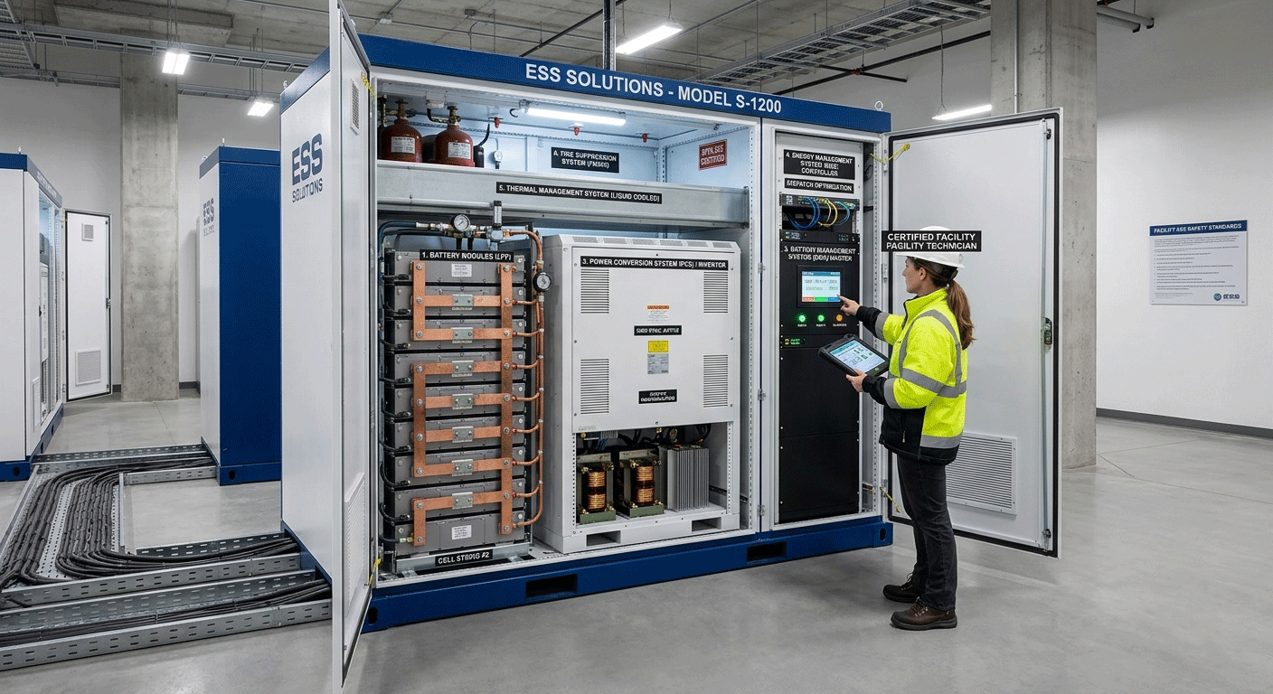
What Are the Main Components Inside an ESS Storage Solution?
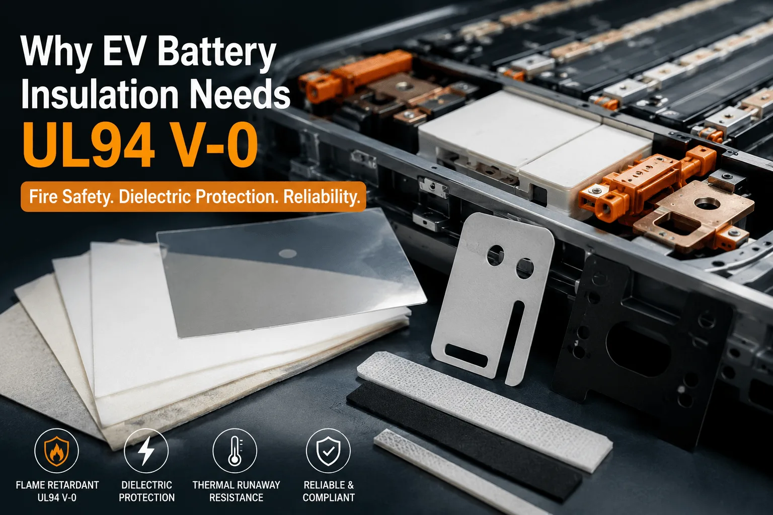
Why Does EV Battery Insulation Need UL94 V-0?
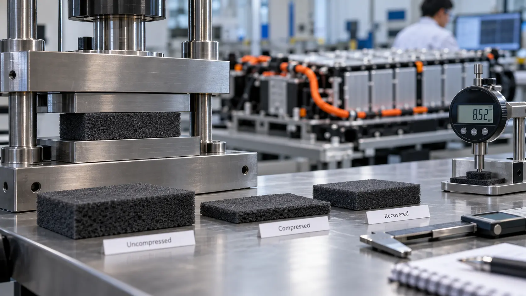
How Do You Test Silicone Foam Recovery in EV Battery Pads?
 betty wong
