
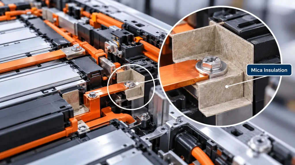
How Does Mica Electrically Insulate EV Battery Packs?
Table of Contents
A battery pack may have excellent cell chemistry and thermal management, but what happens if a busbar, terminal, or energized component moves too close to the enclosure? In a high-voltage EV pack, electrical isolation is not only a material-property problem. It is also a geometry, manufacturing, contamination, aging, and validation problem. Mica is useful because it can provide a solid dielectric barrier while retaining physical integrity under heat, but only when the finished insulator is designed as part of the complete high-voltage system.
⚑ QUICK ANSWER
Key Takeaways
- Mica is a solid dielectric barrier, but a high dielectric-strength datasheet value does not automatically make the complete battery assembly electrically safe.
- Creepage and clearance are functions of the complete geometry. Edges, slots, holes, terminals, fasteners, contamination, and nearby metal can determine the real insulation margin.
- Raw-sheet properties can change after die cutting, lamination, adhesive application, bending, compression, thermal aging, humidity exposure, and installation.
- Busbar and terminal insulation are high-value mica applications because compact high-voltage zones combine energized metal, sharp features, fasteners, and grounded structures.
- Validation should progress from raw material to finished component, assembly, and system level; no single material test proves battery-pack safety.
- For custom parts, DFM and converting quality are part of electrical-insulation engineering, not merely downstream manufacturing.
What Does Electrical Insulation Mean in an EV Battery Pack?
In an EV battery pack, electrical insulation means maintaining intentional separation between conductors at different electrical potentials and between energized high-voltage parts and conductive structures that may be grounded or touch-accessible. The design goal is not simply to stop current through the center of an insulating sheet. It is to prevent unwanted current paths through the material, through air, across surfaces, around edges, and through contamination over the vehicle’s intended life and during defined abnormal events.
That distinction matters because an EV pack is mechanically and environmentally active. Modules expand and contract, fasteners clamp stacks, busbars flex, housings vibrate, condensation or dust can change surface conditions, and service events can introduce debris or damage. The electrical-insulation system therefore includes material selection, insulation coordination, enclosure geometry, attachment method, spacing, surface condition, and verification after environmental and mechanical aging.
For engineers, three related ideas should remain separate. A dielectric barrier opposes current flow through solid insulation. Insulation resistance describes resistance to leakage under specified test conditions. Dielectric withstand or breakdown testing evaluates whether insulation can tolerate a specified electric stress without failure. None of these replaces creepage and clearance analysis, because the shortest electrical path may run around the mica rather than through it.
How Does Mica Provide Electrical Insulation?
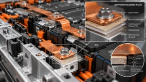
Mica is a family of layered silicate minerals. In engineered electrical-insulation products, mica flakes, splittings, or reconstituted mica paper are typically consolidated with a binder and may be reinforced or laminated with glass fabric, polymer film, pressure-sensitive adhesive (PSA), or other layers. Its mineral structure gives mica strong dielectric behavior, while its inorganic content gives it useful dimensional and physical integrity at temperatures that can severely soften or decompose many polymers.
In an EV battery, that combination is important because the same physical barrier may face two very different conditions. During normal service, it must isolate high-voltage hardware while fitting into a tight package. During abnormal heat exposure, it may need to remain present after an adjacent polymer film, adhesive, carrier, or molded feature has lost stiffness. That does not make every mica construction equivalent: binder chemistry, reinforcement, thickness, moisture condition, temperature, manufacturing history, and test method can materially change electrical and mechanical performance.
Accordingly, engineers should avoid specifying a universal dielectric-strength number for ‘mica.’ The relevant value is grade-dependent, thickness-dependent, conditioning-dependent, and test-method-dependent. A supplier datasheet can support screening, but the production design should be tied to the exact grade and finished construction, including any adhesive and lamination, at the minimum permitted thickness.
Industry Insight 1 — Higher-voltage architectures raise the value of insulation coordination
As EV platforms move toward higher DC bus voltages, electric-field stress and spacing decisions become less forgiving. The practical implication is that engineers and buyers should review geometry, surface paths, fastener interfaces, and production variation together rather than asking only for a material with a higher dielectric-strength value. IEC 60664-1 is a useful insulation-coordination reference for concepts such as clearances, creepage distances, and solid insulation; the applicable automotive requirements still depend on the system and governing standard.
Where Is Mica Electrical Insulation Used in EV Battery Packs?
Mica can be used wherever a battery design benefits from a thin solid barrier that combines electrical isolation with useful high-temperature integrity. The exact location and construction depend on the hazard being controlled.
Busbars and busbar covers
Risk: energized copper or aluminum sits near frames, lids, fasteners, or adjacent conductors.
Why mica: a profiled barrier can isolate the metal and remain dimensionally present during severe heat.
Design focus: edge coverage, bend regions, mounting hardware, sharp busbar edges, adhesive placement, and sufficient creepage around exposed conductor ends.
Cell terminals and interconnect zones
Risk: dense terminal geometry can create short air paths and surface paths around tabs, washers, sensing features, or weld areas.
Why mica: it can create a stable dielectric shield.
Design focus: hole and slot geometry, local tolerances, contamination control, and avoidance of exposed conductive paths.
Module frames and end plates
Risk: cells and interconnects may sit close to conductive structural parts.
Why mica: it can create a solid isolation layer between the active assembly and frame.
Design focus: compression, edge protection, tie rods or fasteners, local metal burrs, and movement over life.
High-voltage junction, fuse, and contactor areas
Risk: multiple conductors, bolted joints, service hardware, and grounded enclosure features occupy a compact region.
Why mica: custom profiles can separate energized hardware from neighboring structures.
Design focus: service clearances, fastener heads, arc or heat exposure, assembly sequence, and inspection access.
Battery enclosure interfaces and pack covers
Risk: energized hardware or conductive debris can approach the metal enclosure, especially during deformation or abnormal events.
Why mica: a dielectric liner can add a solid separation layer.
Design focus: seams, ribs, mounting holes, attachment, vent paths, and avoiding unintended bridges across the barrier.
Selected cell-to-cell locations
Risk: adjacent cells may require both electrical separation and a barrier that retains integrity under heat.
Why mica: it can provide dielectric and flame-facing support.
Design focus: compression, swelling allowance, thermal path, cell venting, and whether a composite with aerogel or foam is more appropriate.
Why Is Mica Useful Around EV Battery Busbars?
Busbar zones concentrate several electrical-insulation risks in one small space. The conductor itself operates at high potential, its edges may be sharp, bolted joints create local protrusions, adjacent module frames or pack structures are conductive, and the available package height may be limited. A simple rectangular sheet may not protect the real fault path if the conductor edge, fastener, or terminal remains exposed.
Custom die-cut mica busbar insulation can be shaped to wrap or shield the high-risk region, add local surface path length, and place a durable dielectric layer between the busbar and nearby metal. Slots, tabs, windows, notches, adhesive zones, and fold lines can be used to fit the assembly sequence. The important engineering question is not whether mica is ‘good for busbars’ in general, but whether the finished profile preserves electrical separation at the worst-case tolerance condition.
Particular attention should be paid to busbar edge radius, burr direction, terminal height, washer and fastener position, coating transitions, and the possibility of movement during vibration or crash deformation. If a metal feature can cut, puncture, or rub the insulator, the local mechanical interface may control electrical reliability. This is why a DFM review should include both CAD geometry and information about the mating conductive parts.
Dielectric Strength vs. Insulation Resistance
Dielectric strength and insulation resistance describe different aspects of electrical behavior. Dielectric strength concerns the electric field a material can withstand before breakdown under a defined test. Insulation resistance concerns leakage through or across an insulation system under specified voltage, time, temperature, humidity, and measurement conditions. A material can have an impressive breakdown value yet still create an unacceptable assembly if surface leakage, contamination, insufficient creepage, or a thin damaged zone dominates the actual current path.
Datasheet comparisons can also be misleading because reported dielectric strength may vary with specimen thickness, electrode geometry, conditioning, ramp rate, and test standard. For procurement, the more useful specification is a defined material grade plus measurable finished-part and assembly requirements: minimum thickness, test voltage and duration, leakage or resistance criteria, conditioning state, and whether testing occurs before or after environmental aging.
Creepage vs. Clearance: Why Mica Alone Is Not Enough
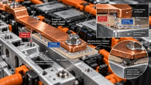
Clearance is the shortest distance through air between two conductive parts. Creepage is the shortest distance along the surface of an insulating material between conductive parts. Both are system-level geometric properties. Adding mica can create a solid barrier and can change the surface route, but it does not automatically correct inadequate spacing around the barrier, a poorly located opening, or a conductive fastener that bypasses the intended path.
Consider a busbar sitting above a grounded aluminum frame. A mica sheet beneath the busbar may prevent direct contact through the center of the sheet. But if the sheet terminates too close to the busbar edge, the shortest path may be around the edge through air or along a contaminated surface. If a mounting hole brings a metal screw close to the conductor, the screw can become the limiting feature. If adhesive squeezes toward the edge, its surface behavior may differ from the mica and should not be assumed equivalent.
Creepage design must also consider the environment. Humidity, condensation, dust, electrolyte residue, processing contamination, and carbonized debris can lower surface resistance or create tracking paths. Comparative Tracking Index (CTI) can be relevant for polymeric insulating surfaces, but it should not be treated as a universal shortcut for an EV assembly. The governing standard, pollution conditions, material group, working voltage, transient stress, altitude, and actual system architecture all influence spacing decisions.
For this reason, this article does not give a universal creepage or clearance distance. IEC 60664-1 provides insulation-coordination principles and methods for determining clearances, creepage distances, and solid insulation within its scope, while automotive systems also need to satisfy the relevant vehicle, battery, and OEM requirements. Engineers should calculate and validate the complete design rather than copy a generic distance from a material brochure.
Why Cut Edges and Holes Can Become Electrical Weak Points
A CAD drawing can specify an excellent mica grade and still produce an unreliable insulator if converting quality is poor. The center of a flat coupon is often the least difficult part of the design. Electrical and mechanical stress concentrates around cutouts, narrow webs, sharp internal corners, mounting holes, unsupported edges, and interfaces with hard metal features.
Edge cracking or delamination can expose a shorter path or reduce local thickness. A hole that drifts toward an energized terminal can reduce both clearance and creepage. A narrow web may fracture during handling. A sharp internal corner can become a crack initiation point. A metal burr can puncture the insulation during clamp-up, while a misregistered laminate can leave adhesive or a lower-performance carrier exposed in the critical zone.
Minimum feature size should therefore be treated as an electrical-insulation variable, not only a manufacturing variable. DFM should review hole diameters, hole-to-edge distance, corner radius, minimum web width, edge finish, fold direction, registration between layers, and the relationship between the die-cut part and the mating busbar, terminal, frame, and fastener. Prototype inspection should use the same critical dimensions that control electrical isolation in the production assembly.
Industry Insight 2 — Precision converting is becoming part of insulation engineering
As battery packaging gets denser, the difference between raw-material capability and finished-component capability grows. For engineers and buyers, this means supplier evaluation should include converting process control, dimensional inspection, edge quality, lamination registration, cleanliness, and packaging—not just a mica datasheet.
What Happens to Electrical Insulation During Thermal Runaway?
Thermal runaway matters here only insofar as it changes the electrical-insulation environment. Severe heat can soften, melt, shrink, or carbonize polymer films. Flame and hot gas can erode surfaces or displace parts. Conductive particles and electrolyte residues can contaminate dielectric surfaces. Pressure and mechanical movement can shift a conductor toward grounded metal. A previously adequate surface path can therefore become shorter, dirtier, hotter, or mechanically damaged.
Mica’s value in this scenario is its ability to retain a mineral-based barrier after many organic materials have lost mechanical integrity. That can help preserve physical separation around busbars, terminals, module structures, or enclosure surfaces. The finished construction still needs scrutiny: binder, reinforcement, adhesive, attachment method, and support can fail before the mica mineral itself. Post-exposure condition—cracking, delamination, displacement, and retained electrical isolation—is more informative than a single maximum-temperature claim.
Mica does not prevent thermal runaway by itself, and a mica insulator does not prove that a battery pack is safe. It is one component in a broader thermal and electrical safety architecture that includes cell design, sensing, current interruption, vent management, structural protection, cooling, spacing, and system-level testing.
Mica vs. PET vs. PI vs. Polycarbonate for EV Electrical Insulation
These materials often overlap in battery insulation, but they are not interchangeable. Functional zoning is more useful than declaring one material universally superior.
| Material | Primary function | Electrical insulation | Temperature capability | Mechanical support | Flexibility | Severe-heat behavior | Typical EV use / limitation |
| Mica | Dielectric barrier with high-temperature integrity | Strong; grade- and construction-dependent | High relative to common polymer films; binder-dependent | Moderate; reinforced/rigid grades available | Flexible to rigid by grade | Mineral phase can remain physically present under severe heat | Busbars, junctions, frames, lids; limitation: brittleness/handling and thermal design depend on construction |
| PET film | Thin dielectric film | Strong in normal service for suitable grades | Moderate; grade-dependent | Low to moderate | High | Can soften, shrink, melt, or decompose in severe heat | Thin wraps, liners, laminated insulation; limitation: severe-heat integrity |
| Polyimide (PI) | High-performance thin dielectric film | Strong; thin-film data are well established for specific grades | High for a polymer; grade-dependent | Low | High | Better heat capability than many common films but still an organic polymer | Thin high-temperature insulation; limitation: cost and limited structural support |
| Polycarbonate (PC) | Dielectric plus mechanical protection | Good for suitable electrical grades | Moderate; grade-dependent | High relative to films | Moderate | Can soften/deform under sufficiently severe heat | Covers, shields, structural liners; limitation: severe-heat integrity |
| Aerogel composite | Thermal resistance | Depends on carrier/composite; not assumed equivalent to dedicated dielectric films | Varies by product construction | Low to moderate | Varies | Excellent thermal resistance; flame-facing durability depends on facing | Cell-to-cell thermal barriers; limitation: handling, dust/edge protection, electrical properties must be verified |
| Silicone foam | Compression and gap management | Can be dielectric by grade | Broad operating range by grade | Low; compliant | Very high | Can char or degrade under extreme exposure | Compression pads, sealing, tolerance management; limitation: not a substitute for a rigid high-temperature dielectric shield |
The correct material often depends on which function is dominant. PET and PI are efficient thin dielectric films; polycarbonate can combine dielectric separation with puncture or structural protection; mica is useful when electrical isolation must coexist with severe-heat integrity; aerogel is primarily selected for thermal resistance; silicone foam is primarily selected for compression, sealing, and gap management. Multi-material stacks are appropriate only when each layer has a defined function and the assembled stack is validated.
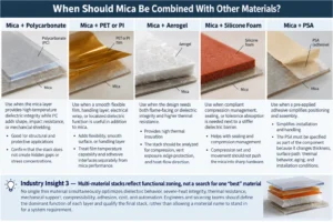
When Should Mica Be Combined With Other Materials?
Mica + polycarbonate
Use when the mica layer provides high-temperature dielectric integrity while PC adds shape, impact resistance, or mechanical shielding. Confirm that the stack does not create hidden gaps or stress concentrations.
Mica + PET or PI
Use when a smooth flexible film, handling layer, electrical wrap, or localized dielectric function is useful in addition to mica. Treat film temperature capability and adhesive interfaces separately from mica performance.
Mica + aerogel
Use when the design needs both flame-facing or dielectric integrity and higher thermal resistance. The stack should be analyzed for compression, vent exposure, edge protection, and heat-flow direction.
Mica + silicone foam
Use when compliant compression management, sealing, or tolerance absorption is needed next to a stiffer dielectric barrier. Compression set and movement should not push the mica into sharp hardware.
Mica + PSA
Use when a pre-applied adhesive simplifies positioning and assembly. The PSA must be specified as part of the component because it changes thickness, surface path, thermal behavior, aging, and installation conditions.
Industry Insight 3 — Multi-material stacks reflect functional zoning, not a search for one “best” material
No single thin material simultaneously optimizes dielectric behavior, severe-heat integrity, thermal resistance, mechanical support, compressibility, adhesion, cost, and automation. Engineers and sourcing teams should define the dominant function of each layer and qualify the final stack, rather than allowing a material name to stand in for a system requirement.
Adhesive Design Matters More Than Many Buyers Expect
Adhesive-backed mica can reduce assembly time and improve part positioning, but the adhesive becomes part of the insulation construction. Raw mica properties are not the same as laminated-component properties. PSA chemistry, coat weight, carrier, thickness tolerance, temperature capability, bond strength, surface preparation, liner design, and coverage pattern can all affect the finished part.
Full-surface adhesive is not always necessary or desirable. Patterned adhesive can reduce squeeze-out near critical edges, leave vent or sensing regions clear, and lower the risk that a lower-performance adhesive becomes the shortest surface path. Conversely, insufficient adhesive can allow lifting, flutter, or positional drift during handling and vibration. The correct pattern depends on installation method and the mechanical support available after final assembly.
Release liner design also matters in production. Split liners, pull tabs, kiss-cut features, and staged liner removal can make a large or complex insulator easier to locate without trapping contamination. Automated assembly may require controlled peel force, part flatness, and liner stiffness. These manufacturing details should be finalized before validation tooling if they influence the installed geometry.
Common EV Battery Electrical Insulation Design Mistakes
- Selecting material only from dielectric strength. Breakdown data are useful, but the assembly may fail around the material rather than through it.
- Ignoring creepage and clearance. A solid sheet cannot compensate for an exposed edge, short air gap, or conductive fastener that bypasses the barrier.
- Putting holes too close to energized features. Hole tolerance, screw position, washers, and stack-up can shrink the real insulation distance.
- Ignoring metal burrs and sharp edges. Local puncture or abrasion can defeat an otherwise capable dielectric sheet.
- Using sharp internal corners and narrow webs. These features can crack during converting, handling, bending, or clamp-up.
- Assuming adhesive has the same electrical and temperature performance as mica. The laminate must be evaluated as a distinct construction.
- Ignoring contamination and humidity. Surface leakage and tracking risk can change after exposure to moisture, dust, process residues, or electrolyte contamination.
- Ignoring dimensional tolerance stack-up. Nominal CAD clearance is not the same as worst-case production clearance.
- Validating raw material but not the finished die-cut component. Edges, holes, lamination, compression, and handling can change the result.
- Treating thermal insulation and electrical insulation as the same requirement. A material optimized for low thermal conductivity may not provide the required dielectric geometry or severe-heat mechanical integrity, and vice versa.
DFM Considerations for Custom Die-Cut Mica Insulators
For a custom die-cut mica insulator, Design for Manufacturing should start before the electrical validation plan is locked. Early DFM can identify geometry that is difficult to cut consistently, likely to crack, or likely to shift during lamination. More importantly, it can identify features where manufacturing variation directly affects electrical spacing.
- Part geometry: identify which contours are electrically critical and which are only packaging boundaries.
- Thickness: specify nominal and minimum finished thickness, including any adhesive or laminate stack that matters to fit or dielectric performance.
- Minimum web width: avoid fragile bridges around windows, slots, and closely spaced holes.
- Hole diameter and position: review fastener head/washer geometry and worst-case positional stack-up, not only the nominal hole center.
- Corner radius: use manufacturable internal radii where the electrical function allows; sharp corners can concentrate stress and cracking.
- Edge quality: define acceptable chipping, cracking, delamination, fiber exposure, or debris for the selected construction.
- Registration: control relative position between mica, films, foam, PSA, liners, printed marks, and cut features.
- Adhesive placement: keep squeeze-out or exposed adhesive away from critical electrical paths unless validated for that function.
- Release liner: design tabs, splits, or staged removal for repeatable assembly and contamination control.
- Kiss cutting: useful for parts supplied on a carrier or liner, but depth control must avoid damaging the functional insulation layer.
- Multi-layer stack: define order, orientation, bonding method, and which layer faces heat, metal, or the installer.
- Dimensional inspection: prioritize characteristics tied to creepage, clearance, alignment, and fit, not only overall length and width.
- Packaging and cleanliness: prevent edge damage, particles, moisture uptake, and distortion before installation.
Industry Insight 4 — Denser packs shift risk toward tolerances and interfaces
Higher energy density generally reduces available space for insulation and can increase the number of functions packed into each millimeter. The implication for engineers and buyers is that tolerance capability, laminate registration, and interface design become more important. A small positional error can consume a meaningful fraction of the intended insulation margin.
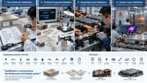
How Should Engineers Validate a Mica Electrical Insulator?
A robust validation plan separates four levels. The tests at each level answer different questions, and passing one level should not be treated as proof of the next.
1. Raw Material Validation
Confirm the exact mica grade, thickness range, binder or reinforcement construction, relevant electrical data, environmental conditioning, and lot documentation. Review the test methods behind dielectric strength and insulation resistance rather than relying on headline values. If flame classification is relevant, remember that UL 94 is a small-scale flammability classification for specified specimens; a V-0 rating is not a thermal-runaway certification and does not demonstrate battery-pack performance.
2. Finished Component Validation
Test production-intent die-cut parts, especially worst-case geometry and minimum permitted thickness. Depending on the program, this can include dielectric withstand, insulation resistance, dimensional inspection, edge inspection, adhesion, thermal aging, humidity exposure, thermal cycling, and post-aging electrical testing. For laminated parts, test the complete construction rather than the mica core alone.
3. Assembly-Level Validation
Install the part with representative busbars, terminals, fasteners, frames, compression, and assembly processes. Evaluate whether tolerance stack-up, clamp load, vibration, abrasion, liner removal, or metal edges damage the barrier. Confirm that the insulator stays in position and that the shortest electrical paths match the design assumptions after aging.
4. System-Level Validation
Validate the relevant battery or vehicle electrical-safety and abnormal-event requirements at system level. ISO 6469-3 addresses electrical safety for voltage class B electric circuits in electrically propelled road vehicles. UNECE Regulation No. 100 contains requirements for electric power train and rechargeable electrical energy storage systems in its applicable markets. Program-specific OEM requirements may be more detailed. No coupon or component test should be presented as proof that the complete pack is safe.
Industry Insight 5 — Qualification is moving toward the finished part and installed system
Raw-material certificates remain necessary, but they are increasingly insufficient for compact high-voltage designs. For engineers and procurement teams, the practical change is to require traceability between the qualified material, converted component, assembly process, and validation sample. Substituting a binder, adhesive, carrier, or converting route can justify re-evaluation even when the word “mica” on the drawing does not change.
Engineering Selection Checklist
Before selecting or releasing an EV battery mica electrical insulator, define the following inputs:
- System voltage and working voltage at the insulation location
- Required dielectric withstand and the associated test method/conditioning
- Required insulation resistance or leakage criterion
- Creepage requirement and governing standard or OEM rule
- Clearance requirement and governing standard or OEM rule
- Operating temperature range and local hot spots
- Abnormal-event temperature/exposure scenario where applicable
- Nominal and minimum finished part thickness
- Mechanical load, clamp pressure, and compression conditions
- Humidity, condensation, dust, electrolyte, or cleaning-chemical exposure
- Thermal cycling and vibration environment
- Metal edge condition, burr control, and puncture/abrasion risks
- Fastener location, washer/head size, and tolerance stack-up
- Adhesive requirement, coverage pattern, substrate, and release liner
- Assembly method: manual placement, fixture, automation, bending, or forming
- Validation plan from raw material through component, assembly, and system level
What to Send With a Mica Insulation RFQ
A useful RFQ gives the converter enough information to identify material, geometry, lamination, and manufacturing risks before tooling or production. Send:
- PDF drawing plus DXF and/or STEP geometry where available
- Application location and a brief description of the mating parts
- System and working voltage relevant to the part
- Target mica grade or approved material family, if already defined
- Nominal and minimum thickness requirements
- Critical dimensional tolerances and datum scheme
- Dielectric withstand, insulation resistance, and conditioning requirements
- Operating temperature range and abnormal/fault temperature or exposure scenario
- Adhesive type or functional requirement, coverage area, substrate, and liner preference
- Lamination or multi-layer stack requirements
- Prototype quantity and development schedule
- Expected annual volume and packaging unit
- Required component or assembly validation support
- PPAP or customer-specific quality documentation requirement
- Packaging, cleanliness, and handling requirements
- Lot identification and traceability requirements
From Mica Sheet to Assembly-Ready Insulation Component
The commercial distinction is important: sourcing mica sheet is not the same as sourcing a repeatable electrical-insulation component. The production part may require material selection support, DFM, precision die cutting, multi-layer lamination, adhesive integration, prototyping, dimensional inspection, packaging, and volume manufacturing. Boost Insulation’s current EV battery module-insulation pages describe engineering/DFM support, die cutting and CNC processing, multi-layer lamination, adhesive/film integration, and mica/aerogel/film/foam material combinations. Those capabilities align with projects where the electrical function depends on both material and converted geometry.
For buyers, the useful supplier conversation therefore starts with the drawing and failure modes, not only with a request for a mica price per square meter. A converter should understand which edges, holes, fastener zones, and laminate interfaces are electrically critical, because those features should drive process selection and inspection. If the raw sheet passes but the installed part cracks, misregisters, lifts, or leaves a conductive bypass path, the insulation system has not succeeded.
Engineering Project CTA
Send Boost Insulation your PDF/DXF/STEP drawing, system voltage, target mica grade and thickness, creepage and clearance constraints, operating and fault exposure conditions, adhesive or lamination requirements, prototype quantity, and annual volume. The engineering team can review the geometry, material stack, and converting risks before prototype tooling or production release. Contact
Frequently Asked Questions
Is mica electrically insulating?
Yes. Mica is widely used as an electrical-insulation material because engineered mica products can provide high dielectric resistance while remaining stable under heat. The exact performance is not universal, however. Mica type, binder, reinforcement, thickness, moisture condition, temperature, and test method all matter. In an EV battery, the useful question is whether the finished mica component preserves isolation at edges, holes, fasteners, and interfaces after manufacturing and environmental aging.
Why is mica used for high-voltage EV batteries?
Mica can combine electrical isolation with high-temperature physical integrity in a thin barrier. That is useful around busbars, terminals, module structures, junction areas, and enclosure interfaces where a polymer-only layer may lose stiffness under severe heat. Mica is not a complete safety solution; it must be coordinated with creepage, clearance, mechanical protection, contamination control, thermal management, and system-level validation.
Can mica insulate EV battery busbars?
Yes. Mica can be die cut into busbar covers, separators, shields, and local dielectric barriers. Busbar applications should be designed around exposed conductor edges, bolted joints, fasteners, nearby grounded structures, vibration, metal burrs, and worst-case tolerance stack-up. The required geometry and thickness depend on the voltage, material grade, applicable standards, environment, and validation plan.
Is mica better than PET or polyimide for electrical insulation?
Not universally. PET and polyimide are efficient thin dielectric films, and polyimide can offer strong high-temperature performance for an organic film. Mica is particularly useful when the insulation must also retain a mineral-based physical barrier during severe heat. The appropriate material depends on thickness, flexibility, mechanical support, temperature exposure, assembly method, cost, and the required validation. Hybrid constructions are common when functions differ by layer.
Does mica remain electrically insulating at high temperatures?
Mica is valued because its mineral phase retains electrical-insulation and physical-barrier characteristics at temperatures that can damage many polymers. But the finished product also contains binders, reinforcement, adhesive, and possibly films or foam. Those layers may degrade earlier. High-temperature performance is therefore grade-dependent and construction-dependent, and should be validated after representative heat exposure rather than assumed from the mica mineral alone.
How thick should mica electrical insulation be?
There is no universal thickness for an EV battery insulator. Required thickness depends on material grade, test method, working voltage, dielectric-withstand target, geometry, mechanical loading, manufacturing tolerance, heat exposure, and the required safety margin. Creepage and clearance can also dominate even when through-thickness dielectric capability is high. Specify a minimum finished thickness and qualify the exact construction at worst-case production conditions.
Can adhesive-backed mica be die cut?
Yes. Mica can be laminated with pressure-sensitive adhesive and converted into custom die-cut parts, including kiss-cut constructions on a release liner. The adhesive system should be treated as part of the component. Review temperature capability, dielectric behavior, bond durability, coverage pattern, squeeze-out, thickness tolerance, liner design, substrate compatibility, and whether adhesive placement changes critical surface paths.
What information is needed for a custom mica insulation quote?
Provide the PDF drawing and preferably DXF/STEP data, application location, voltage, target mica grade, thickness, critical tolerances, dielectric requirements, operating and fault exposure conditions, adhesive/lamination needs, prototype quantity, annual volume, validation expectations, PPAP requirements, packaging, and traceability. Highlight features that control creepage, clearance, fastener separation, or alignment so the DFM review focuses on electrically critical dimensions.
Related Posts:
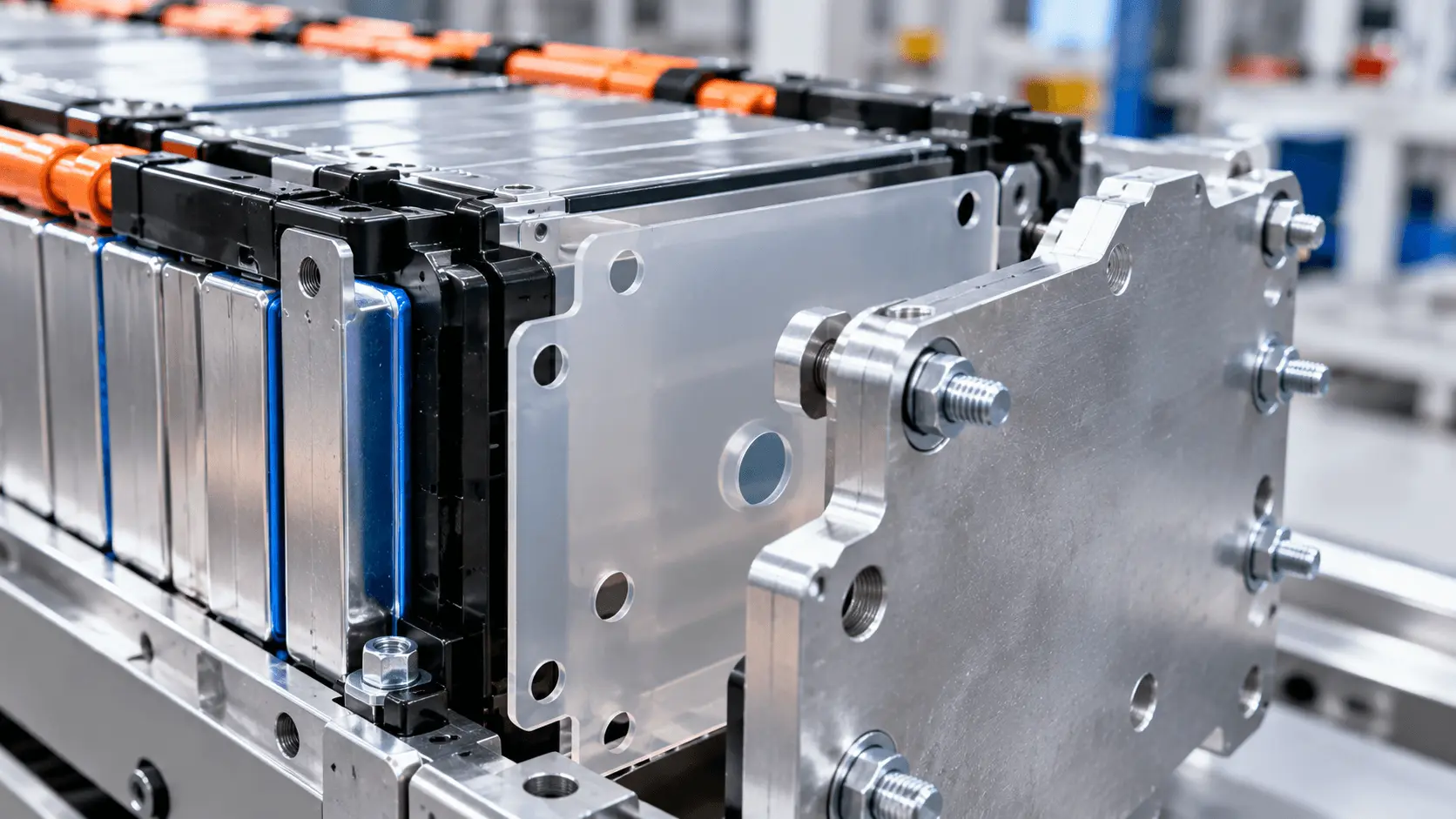
How Does PC Insulation Protect EV Battery End Plates?
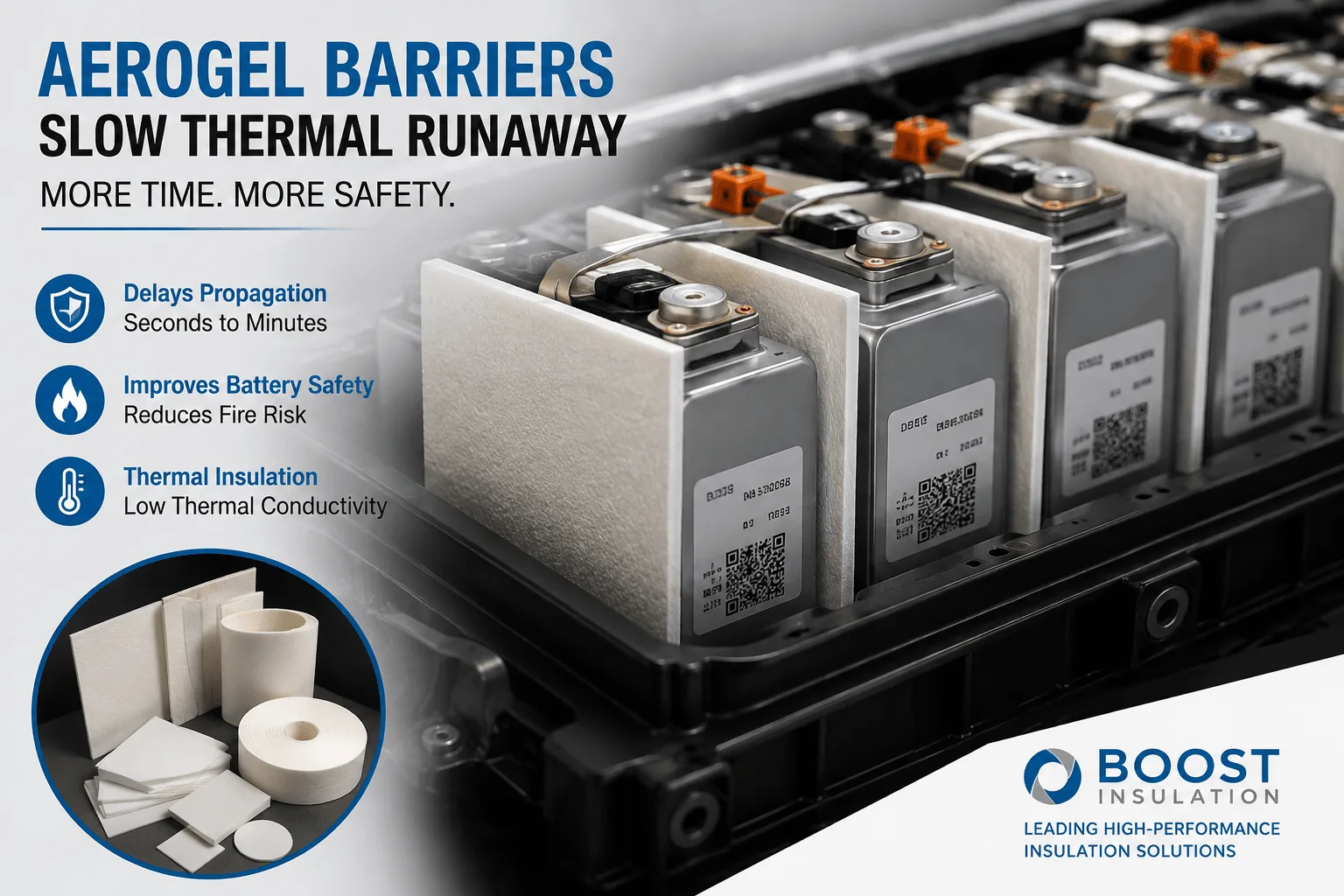
How Much Delay Can an Aerogel Barrier Provide in EV Packs?
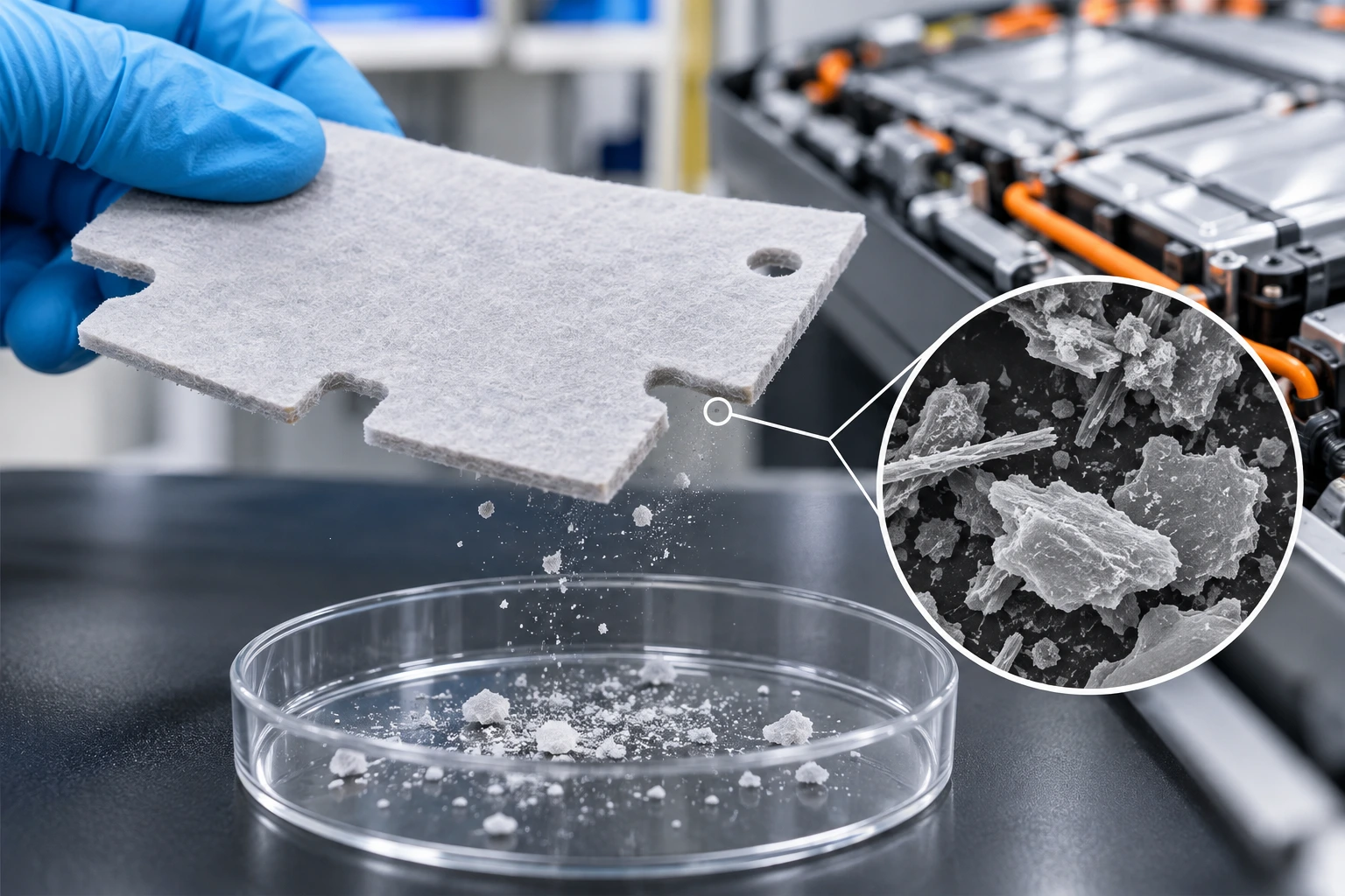
How Do You Measure Particle Shedding From Die-Cut Aerogel?
How Do You Select Aerogel Thickness Between Cells?
How Does a Mica Insulation Sheet Protect EV Batteries?
How Does a Mica Insulation Sheet Compare With FR4 Boards?
 betty wong
