
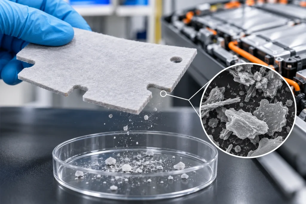
How Do You Measure Particle Shedding From Die-Cut Aerogel?
Table of Contents
A die-cut aerogel insulation pad can meet its dimensional drawing and appear undamaged, yet still release loose particles during pick-and-place handling, packaging, or installation in an EV battery module. Surfaces, cut edges, and packaging can contribute particles. Appearance alone does not establish a cleanliness result. Battery engineers need to know exactly what was released, under which handling conditions, how it was collected, and whether the result meets the assembly’s specific contamination requirements.
Engineers measure particle shedding from die-cut aerogel by identifying the material grade and finished-part geometry, conditioning representative specimens, and applying a defined handling or mechanical exposure. Released particles are collected using a documented procedure with appropriate environmental, procedural, and handling blanks. Depending on the risk, laboratories measure collected mass, particle count, size distribution, or particle identity, while evaluating collection efficiency and repeatability. Results are reported per component or another justified geometric basis and compared with customer-defined acceptance criteria. Distinguish induced shedding from pre-existing contamination without unrepresentative specimen damage.
Why Does Particle Shedding Matter in EV Battery Aerogel Pads?
Aerogel cell-to-cell barriers are converted parts that pass through cutting, inspection, protective packaging, transport, liner removal, and module assembly. Each operation may expose loose material or transfer particles already resting on the surface. An EV battery manufacturer therefore needs to establish which released particles could reach sensitive locations: adhesive-bonding surfaces, connector housings, sensing hardware, busbar interfaces, tooling, or an inspection camera. Potential consequences depend on particle chemistry, size, number, location, and migration path; not every particle causes a functional failure.
The key question is whether the part releases acceptable debris during assembly, not why aerogel slows cell-to-cell heat transfer.
Industry Insight 1 — Shedding depends on exposure. A pad that appears clean after stationary inspection may release material when gripped, slid, unpacked, or bent. Conversely, severe rubbing may create debris unrelated to ordinary assembly. Qualifying a release result therefore requires a documented mechanical history, not simply the word “dusting.”
What Is the Difference Between Shedding and Residual Contamination?
Particle shedding is the release of particles from a part during an explicitly defined operation or exposure. Residual contamination is particulate material present on or associated with the part before that operation. Particle generation means a process creates new debris, while particle release describes its detachment or transfer to a collection environment. A loose fragment made during die cutting may later fall from a pad during installation; it is released during installation but was not necessarily generated then.
This distinction determines the test design. A residual-cleanliness inspection may extract particles already present without applying realistic use-related loading. A shedding test deliberately applies a relevant stimulus and measures what that stimulus releases. A combined method is possible, but the sequence, preconditioning, extraction, and result attribution must be disclosed. ISO 16232’s cleanliness framework does not validate arbitrary aerogel abrasion tests.
What Types of Particles Can a Finished Aerogel Part Release?
Potential constituents include aerogel-rich fragments, ceramic-fiber fragments, reinforcement debris, dust from an exposed face, loose cut-edge chips, adhesive-related material, liner fragments, and external packaging contamination. The mix depends on the approved laminate. Fiber-like morphology alone does not identify ceramic composition.
| Potential Source | Release Mechanism | Identification Method | Engineering Concern |
| Broad felt face | Handling contact or local surface disturbance | Documented surface collection; microscopy | Transfer to mating cell or tooling |
| Exposed die-cut perimeter | Edge fragmentation or trapped cutting debris | Edge-versus-face comparison; imaging | Debris from long or intricate profiles |
| Holes, slots, and notches | Local cutting and later contact | Region-specific inspection and collection | Release near sensors or fasteners |
| Fiber reinforcement | Fragment detachment under defined load | Morphology; chemistry if required | Fiber-like particles entering assembly |
| Film, adhesive, or liner | Interfacial damage or liner removal | Controls for individual layers | Non-aerogel particulate contamination |
| Packaging and fixtures | Abrasion or external transfer | Packaging blank and fixture blank | False attribution to the aerogel |
The table lists hypotheses to investigate, not confirmed emissions from any particular Boost Insulation product.
Where Should Engineers Look for Particle Sources?
Map the finished profile: broad-surface area, exposed edge length, cutouts, narrow bridges, facings, and gripper contact zones. Two parts cut from one sheet may shed differently if their exposed perimeters differ. A general inspection photograph cannot prove the particle source.
To compare sources, test broad-face reference specimens, edge-exposed references, and actual finished components under controlled, comparable loading. Masking or isolating surfaces may be informative only if the masking itself does not alter the release mechanism. Do not assume cut edges caused all collected debris simply because the part was die-cut.

How Do You Define a Representative Shedding Test?
Begin with the intended decision: material screening, die-cut process approval, packaging verification, incoming inspection, or assembly-risk qualification. Then translate the expected operation into controlled contact area, grip location, number of handling events, pressure or displacement where relevant, motion, duration, and environmental conditions. Distinguish customer inputs from method requirements; avoid arbitrary loads.
| Exposure Method | Application Scenario | Required Controls | Test Limitation |
| Controlled pick-and-place | Gripper transfer to module fixture | Contact material, force, location, repetitions | Does not capture transport vibration |
| Contact transfer | Touching a defined mating surface | Contact area, pressure, dwell, separation | Captures transfer, not all airborne release |
| Representative sliding | Installation across a guide or carrier | Travel, contact load, surface roughness | May exaggerate abrasion if poorly matched |
| Packaging / unpacking | Removal from trays or protective layers | Stack orientation, packaging revision, unpacking method | Packaging particles may be counted too |
| Agitation or vibration | Specified transport or handling event | Fixture, loading spectrum, duration, orientation | Not equivalent to normal manual assembly |
| Local bending | Only when handling requires deformation | Geometry and cycles justified by use | Mechanical damage merits separate qualification |
Specify whether particles are captured during movement or by subsequent collection: these measure potentially different fractions and should not be compared without qualification.
How Should Representative Aerogel Specimens Be Prepared?
General aerogel grade verification establishes traceable identity; the shedding test adds controlled evidence about the finished component.
Record supplier, grade, construction, thickness, facings, drawing revision, and lot. Measure or document outer dimensions, exposed edge length, available surface area, major cutouts, and starting condition. Retain specimens from relevant stages: incoming felt, converted parts, packaged parts, and—where feasible—parts subjected to representative installation. Controls should follow the same conditioning and handling history except for the intended exposure variable.
Select sample quantity from the customer plan and method variability; aerogel has no universal sample count. Avoid pre-cleaning a specimen unless the procedure explicitly requires it, because pre-cleaning may remove residual debris, change the surface, or create new particles. Document any preconditioning temperature, humidity, holding time, and the point at which packaging is opened.
How Do Background Blanks Prevent Misleading Results?
A procedural blank follows collection and analysis steps without a test part. A handling blank evaluates particle contribution from the operator, gloves, tools, or fixture operations; a packaging blank can evaluate tray or liner contribution separately. Collection media need their own baseline. These controls expose contamination that might otherwise be wrongly credited to aerogel. They are especially important near the detection capability of the chosen measurement method.
Measure and report blank variability rather than assuming a single blank subtraction always solves the problem. A blank-corrected result near zero may still have substantial uncertainty. If blanks approach the amount collected from the sample, improve the procedure or report that the method cannot reliably distinguish the component signal. Environmental air classification does not substitute for part-specific blank control.
| Error Source | Potential Impact | Control Method | Reporting Requirement |
| Collection-media residue | Artificially increases mass or count | Media blank / matched preparation | Blank results and treatment |
| Fixture and glove shedding | False component attribution | Handling blank and fixture cleaning | Contact materials and blank history |
| Airborne background | Particles enter open collectors | Controlled workstation and field blank | Environmental controls |
| Transfer loss | Underreports released mass or count | Transfer validation; retained-media checks | Estimated recovery limitation |
| Incomplete capture | Misses particles leaving collection zone | Capture design and efficiency assessment | What fraction the method observes |
| Different size thresholds | Invalid count comparison | Agreed lower detection/classification limit | Instrument settings and size bins |
| Uncontrolled specimen history | Adds handling or humidity variation | Standardized storage and conditioning | Conditioning / packaging record |
Industry Insight 2 — Low readings require stronger controls. When the measured signal is small, blank particles and recovery losses can dominate the apparent result. A supplier cannot credibly promise “zero particles” merely because a particular method returned no detectable particles above its stated threshold.
How Should Released Particles Be Collected?
Choose collection around the question being answered. A clean witness surface can capture particles transferred by contact; a controlled enclosure with appropriate collectors may capture material released during movement; a membrane can retain material transferred from a compatible collection medium. Airborne sampling can answer an airborne-concentration question, but sampling flow and capture location must be appropriate. The chosen method must document the collection zone, material losses and potential substrate interactions.
Liquid extraction can be useful for some automotive components, but a porous, fragile aerogel may absorb liquid, disperse material, change its structure, or release particles by the extraction itself. Before adapting an extraction method, test compatibility on sacrificial specimens and compare it with the intended handling exposure. Report whether the objective is residual particulate cleanliness, induced release, or both.
The revised 2026 VDA 19.1 guidance includes expanded dry-extraction and analysis options, but suitability for the particular aerogel grade and procedure still requires method development. A reference to a cleanliness guideline is not evidence that the aerogel, supplier or laboratory has obtained a specific certification.

How Do You Measure Particle Mass, Count, and Size?
Three measurement outputs answer different engineering questions. For gravimetric analysis, determine the mass retained on suitably prepared collection media, account for baseline media mass and controlled conditioning, and report the result with uncertainty and collection efficiency considerations. Weighing the specimen before and after exposure provides a different metric: a change can include moisture effects, lost fragments that were never captured, or handling changes. Specimen mass loss is not equal to collected particle mass by definition.
Microscopy or suitable imaging may count detectable particles and classify their projected dimensions. State the method’s size threshold, imaging resolution, examined area, overlapping-particle rule, and treatment of fibers or irregular fragments. Counts from different thresholds cannot be compared as equal. Size distributions reveal whether the result includes many small particles, a few large fragments, or fiber-like objects; none is automatically more critical without the assembly’s risk model.
| Method | Measured Output | Important Controls | What It Cannot Prove |
| Pre/post specimen weighing | Net change in specimen mass | Conditioning, scale sensitivity, handling | Exact mass or identity of captured particles |
| Collected-particle gravimetry | Mass retained on medium | Media tare, blank, transfer recovery | Particle count or size distribution |
| Optical microscopy / imaging | Count and projected particle dimensions | Size threshold, coverage, classification rules | Chemical identity from appearance alone |
| Targeted chemical characterization | Composition of selected recovered particles | Representative selection, contamination control | Composition of every particle in the lot |
| Contact witness collection | Transfer to a defined surface | Contact pressure, material, separation | Total release to all environments |
| Airborne collection | Particles detected in a defined sampled air volume | Airflow, enclosure, sampler position | Total settled or contact-transferred debris |
Industry Insight 3 — Mass and count are complementary. A heavy fragment can outweigh hundreds of smaller particles, while a high count can contribute little mass. Customer specifications should identify which burden threatens the assembly and require the corresponding measurement rather than substituting a convenient number.
How Can Engineers Identify Fibers and Other Particles?
Classify visible particles first by reproducible morphology—compact, elongated, film-like, or irregular—at a known optical resolution. A high aspect ratio is a useful descriptor but does not establish that a fragment is a ceramic fiber. When material identity affects acceptance, consider appropriate microscopy and elemental analysis such as SEM/EDS on selected particles, with background controls and limitations recorded. Elemental evidence may help differentiate an inorganic fragment from polymeric packaging material, but identification must remain consistent with what the analytical method can actually resolve.
Particle morphology and composition do not independently establish occupational health classification; workplace exposures require separate material safety and industrial hygiene evaluation. A shedding inspection is not a toxicological certification.
How Should Engineers Normalize and Compare Results?
For an OEM accepting a specified part, particles per component or mass per component often aligns most closely with potential delivered contamination. For process development, counts per exposed edge length or per measured face area can help compare geometries. Always report the denominator, geometry, and inclusion or exclusion of cutouts. An edge-normalized result is a diagnostic process indicator, not a substitute for a per-part cleanliness limit at assembly.
| Metric | What It Measures | Engineering Value | Main Limitation |
| Mass per finished part | Collected burden associated with one part | Incoming/finished-part acceptance | Hides count and size |
| Count per finished part | Detected particles above defined threshold | Direct part-to-part comparison | Highly sensitive to threshold |
| Count by size class | Distribution of detectable fragment sizes | Screens application-specific critical classes | Does not itself determine composition |
| Count per face area | Result normalized to accessible surface | Screens differences between flat specimens | May hide long cut perimeters |
| Count per exposed edge length | Result relative to exposed cutting geometry | Compares edge-related process designs | Cannot prove the particles came only from edges |
| Fiber-like count per part | Morphology-classified objects | Tracks a specific inspection concern | Fiber-like is not chemical identification |
Industry Insight 4 — Cut edges and broad faces need controlled comparisons. A large panel with little perimeter differs from a small perforated pad with long internal cuts. Report total part burden alongside optional process-development normalizations, and avoid attributing every recovered particle to cutting without source-specific evidence.
How Do Packaging, Facings, and Adhesives Change the Result?
Test parts immediately after converting and after the specified packaging or handling sequence when both stages matter. Stacking pressure, tray movement, liner separation, protective film edges, and unpacking motions can change the mixture of loose material and externally introduced contaminants. Compare packaging configurations using matching parts and a packaging-only blank; do not infer contamination mechanisms from a single post-shipment particle count.
Protective facings or adhesive constructions may help retain material in some designs, but can introduce adhesive transfer, torn film fragments, exposed cut-core zones, or different stiffness and contact behavior. The validation specimen should match the approved finished bill of materials. A bare felt coupon cannot automatically substitute for an adhesive-backed, faced production pad. Boost’s aerogel insulation product page describes custom converting and multilayer configurations; exact grade, edge design, and the customer’s contamination criterion still require project review.
What Do Repeatability, Collection Efficiency, and Uncertainty Mean?
A repeatable test gives acceptably consistent outcomes under the same documented conditions. A reproducible test also addresses differences between personnel, equipment, days, or laboratories when that comparison is required. Shedding may be inherently heterogeneous: a local nick, different gripper placement, or a lot-level surface variation can change the result. Report individual specimen values when possible, not only an average that obscures occasional large fragments.
Collection efficiency addresses whether released material reaches and remains in the measurement system. Characterize recovery without creating an unrealistic aerogel release mechanism. Measurement uncertainty also includes blank variation, instrument capability, sampling and particle classification. A result close to an acceptance boundary should trigger the agreed decision rule rather than an automatic pass based on excessive numerical precision.
How Should EV Battery Teams Set Shedding Acceptance Criteria?
Use the battery architecture and material requirements in the aerogel insulation selection guide as context, without treating that broader guide as a particle measurement standard.
Start with the sensitive location and the consequence of contamination. Determine whether the critical risk is transferred mass on an adhesive surface, large foreign fragments near a high-voltage interface, fine debris accumulating on assembly tooling, or another verified mechanism. Then select a representative exposure, the relevant mass/count/size metric, the per-part or normalized basis, test method capability, and a supplier/customer decision rule. There is no universal shedding limit for all die-cut EV aerogel components.
| Requirement | Customer Input | Supplier Evidence | Acceptance Question |
| Critical contamination location | Sensitive interfaces and migration paths | Risk review and sample geometry | Is the tested exposure representative? |
| Approved material construction | Grade, facing, adhesive, revision | Traceability and controlled BOM | Does the evidence cover this finished part? |
| Particle metric | Mass, count, class, or identity | Defined laboratory procedure | Does the output measure the actual risk? |
| Exposure conditions | Handling, packing, assembly simulation | Fixture and procedural record | Are conditions repeatable and justified? |
| Measurement validity | Blank, capture, threshold, variability | Raw data and method qualification | Can the signal be distinguished from background? |
| Release acceptance | Program-specific criterion and rule | Individual results and disposition | Is this lot accepted under the agreed rule? |
| Packaging release | Approved tray, liner, storage condition | Post-packaging inspection if required | Is cleanliness maintained through delivery? |
Do not mistake passing a particle limit for proof that the complete battery pack is safe. Contamination-sensitive system validation remains an OEM or system integrator responsibility. ISO 16232:2018 explicitly leaves component-specific cleanliness limits to the relevant specialists and does not impose one universal numerical threshold.
Industry Insight 5 — Geometry is part of the cleanliness specification. A drawing change that introduces another slot, a narrower bridge, or a new exposed edge can change the available release surfaces even if the raw aerogel grade remains unchanged. Supplier change control should therefore consider both material and converted-part revisions.
What Should a Supplier Particle-Shedding Report Include?
A supplier report must connect every result to the component revision and lot. Record purpose, sample selection, packaging condition, material construction, geometry, exposure fixture, conditioning, collection media, blanks, analysis settings, size thresholds, particle classifications, individual and normalized results, deviations, method limitations, and acceptance rule. Include traceable images when they inform identification or disposition.
Separate customer-required fields from method-dependent fields. SEM/EDS is unnecessary in routine reports unless identity matters; cleanroom classification is not a part-level particle limit. A controlled procedure and raw evidence support a meaningful pass/fail decision.
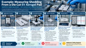
Example: Measuring Shedding From a Die-Cut EV Aerogel Pad
Hypothetical engineering example — not a Boost customer test or reported test result. A module designer plans to install a ceramic-fiber aerogel pad between prismatic cells. The part includes exposed outer edges, a locating slot, and a narrow bridge. The assembly team identifies a sensitive adhesive interface nearby and requests a controlled pick-and-place release assessment before prototype approval.
Engineering defines the approved grade and drawing revision, then selects representative die-cut parts and matching blanks. The agreed fixture reproduces the intended handling contact rather than intentionally abrading the material. Particles are collected using a method shown to be compatible with the aerogel and the anticipated release path. The team evaluates a customer-selected mass or count metric, documents its threshold and collection limitations, and compares the individual results against the program’s predetermined acceptance rule. Because the slot may change shedding behavior, it is included in the finished geometry rather than replaced by a rectangular raw-felt sample.
The decision is recorded as Accepted, Rejected, or Additional Testing Required. The example intentionally specifies no invented particle count, test duration, extraction recovery, acceptance limit, or passing outcome.
Common Mistakes in Aerogel Shedding Measurement
- Calling a part “low dust” without a procedure: The claim lacks a testable boundary; define exposure, collection, and metric.
- Confusing residual contamination with induced shedding: The result answers the wrong question; specify initial and post-exposure states.
- Ignoring grade and construction: Material substitutions invalidate comparison; record the approved grade and facing revision.
- Ignoring finished-part geometry: Flat coupons miss slots and perimeters; test drawing-representative parts.
- Testing raw felt alone: Conversion can alter release behavior; qualify the finished construction separately.
- Omitting exposed edge length: Geometry comparisons become misleading; document perimeter and internal cuts.
- Using undefined handling: Operator variation dominates; use a controlled, representative action.
- Ignoring environmental particles: Background inflates the result; control air and work surfaces.
- Skipping blanks: Component attribution is uncertain; include appropriate media, procedural, and handling controls.
- Equating mass loss with captured mass: Uncollected debris and conditioning distort results; measure the intended output directly.
- Using mass alone when size matters: Large critical fragments may be obscured; add relevant particle classes.
- Comparing different optical thresholds: Apparent improvement may be instrument-driven; standardize detection limits.
- Calling all fragments ceramic fibers: Appearance is insufficient; classify morphology and confirm identity when required.
- Ignoring recovery and repeatability: Results cannot support supplier acceptance; characterize method capability.
- Inventing universal limits: Customer risk is not addressed; define application-specific acceptance and disposition.
Engineering Checklist for Aerogel Particle-Shedding Testing
Confirm the application and part: battery position; contamination-sensitive interfaces; supplier; grade and construction; thickness; facing/adhesive; drawing revision; total surface area; exposed perimeter; holes, slots and bridges; incoming lot; packaging state; initial visual condition.
Confirm the test procedure: screening or acceptance objective; conditioning; representative exposure and fixture; contact materials; motion and duration; background controls; procedural, handling and packaging blanks as needed; collection medium; transfer pathway; possible material/extraction incompatibility; capture efficiency; required sample selection.
Confirm the measurement and disposition: collected mass, count, size bins or identity as appropriate; lower detection threshold; microscopy/classification rules; blank variability; recovery limitation; individual results; normalization basis; repeatability; uncertainty; customer limits; decision rule; report revision; material traceability; package verification; approval authority.
RFQ Checklist for Custom Die-Cut Aerogel Insulation Pads
Send the application package: battery cell/module location, thermal-barrier purpose, sensitive nearby interfaces, expected handling sequence, packing/unpacking requirements, and available assembly model. Provide a PDF drawing plus DXF/DWG or other agreed CAD format, specifying nominal thickness, profile, holes, cutouts, narrow bridges, critical edges, orientation, facing or adhesive layers, and prototype/annual demand.
Send the cleanliness requirement: whether the objective is residual contamination, induced shedding, or both; representative exposure; collection compatibility constraints; preferred measurement metric and size threshold if established; sample plan; program acceptance criterion; reporting requirements; and customer validation responsibilities. If limits are not yet defined, supply the contamination risk, sensitive locations, handling conditions, and measurement objective so the test specification can be developed rather than invented.
How Boost Insulation Supports Custom Die-Cut Aerogel Components
Boost Insulation’s aerogel product page describes material selection, drawing and DFM review, die-cut converting, and prototype-oriented services. Its EV battery module insulation page also describes multilayer converting. For a shedding-sensitive request, customers should review the proposed aerogel grade, perimeter geometry, facings, packaging requirements, and inspection expectations before tooling is released. Confirm specialized particle-counting or chemical-characterization evidence with the supplier or a qualified laboratory; published manufacturing capabilities do not establish laboratory accreditation.
Industry Insight 6 — Acceptance is a chain of evidence. A raw-material certificate, good die-cut dimensions, and an attractive packaging photo cannot replace a defined component cleanliness result. Conversely, even an accepted part-level result does not remove the need to manage particle sources elsewhere in battery assembly. Link material approval, converting conditions, delivery state, and the customer’s system-level controls.
Frequently Asked Questions
1. How do you measure particle shedding from die-cut aerogel?
Define a representative handling, contact, or packaging exposure for the actual finished component. Condition and identify specimens, run background and handling blanks, then collect released particles with a documented, aerogel-compatible method. Measure the relevant mass, count, size distribution, or composition, noting detection limits and recovery. Report results per part or an explicitly justified normalization basis, and compare individual results with the battery customer’s acceptance rule.
2. Why can die-cut aerogel release particles during handling?
Potential sources include loosely attached material on broad faces, debris retained after cutting, exposed composite edges, damaged narrow sections, and facing or adhesive fragments. Pick-and-place contact, liner removal, sliding, and unpacking may transfer particles that already existed or create new debris. The size and amount of release depend on the grade, geometry, conversion process, and handling conditions. The source should be investigated, not assumed from appearance.
3. What is the difference between particle shedding and residual contamination?
Residual contamination describes particles present before the defined exposure, while shedding describes particles released during that exposure. A fragment made by die cutting can remain attached until the component is handled, so a later release does not establish when it was generated. To separate the questions, document the initial part condition and specify whether the method is a residual-cleanliness extraction, induced-release test, or deliberately combined procedure.
4. Should engineers measure particle mass or particle count?
Select the metric from the contamination-sensitive application. Collected mass helps quantify total particulate burden, whereas count and size classes show how that burden is distributed among detectable fragments. A few large pieces and numerous small particles may have similar mass but different practical consequences. When necessary, combine methods and record their thresholds. Neither mass alone nor count alone proves chemical identity or battery assembly cleanliness.
5. How can ceramic fibers be distinguished from other aerogel particles?
Optical microscopy can classify elongated, fiber-like objects and describe their measured dimensions, but morphology is not proof of a specific ceramic composition. If identity affects acceptance, selected particles may require suitable additional characterization such as SEM/EDS, with representative sampling and background controls. Other fragments can originate from aerogel, adhesives, protective films, packaging, or the test fixture. The report should distinguish observation from confirmed identification.
6. Can ISO 16232 or VDA 19.1 be used for aerogel cleanliness testing?
ISO 16232:2018 provides an automotive component particulate-cleanliness framework; VDA 19.1 offers technical-cleanliness inspection guidance, including a revised 2026 edition. They can inform method development, reporting, and laboratory practices. However, residual contamination inspection is not automatically an induced-shedding test, and aggressive extraction may disturb porous aerogel. Validate material compatibility, exposure relevance, collection performance, and acceptance rules before asserting applicability to a specific aerogel component.
7. How should particle-shedding acceptance limits be established?
Start with the battery assembly’s sensitive locations, possible particle migration, and consequences of contamination. Define the representative handling exposure, the critical measurement metric, any relevant particle-size classes, and the required analytical capability. Then agree a lot-level decision rule supported by blanks and repeatability evidence. There is no universal particle-shedding limit for all EV battery aerogel pads; limits must be established for the application and verified method.
8. Should suppliers test raw aerogel sheets or finished die-cut pads?
Both can be useful, but they answer different questions. Raw-sheet specimens help screen material grades and incoming variation. Finished die-cut pads include actual perimeters, holes, narrow bridges, adhesives, and packaging interfaces that may change particle release. For component acceptance, use drawing-representative finished parts under specified handling conditions. Where delivery cleanliness matters, consider an additional post-packaging assessment rather than assuming cutting-stage results remain valid through shipment.
Request a DFM Review for Custom Die-Cut Aerogel Pads
If you are sourcing die-cut aerogel insulation for an EV battery, share your material grade or candidate, part drawing, thickness, exposed cut-edge geometry, cutouts, handling and packaging conditions, cleanliness expectations, requested shedding metric, prototype quantity, and annual volume. A material and manufacturability discussion can establish which component details and inspection evidence should be confirmed before samples are submitted for customer validation.
Send Aerogel Part Drawing + Particle-Shedding Requirements + Handling Conditions → Material / DFM Review → Prototype Request.
Related Posts:

How Does Battery Aerogel Insulation Work in EV Packs?

What Insulation Does an Energy Storage System Need?

How to Choose EV Battery Cell Insulation Pads?
How Can You Prevent UV Yellowing in FR Polycarbonate?

How Do You Design Die-Cut PC Battery Insulation?

Why Does EV Battery Insulation Need UL94 V-0?
 root
