
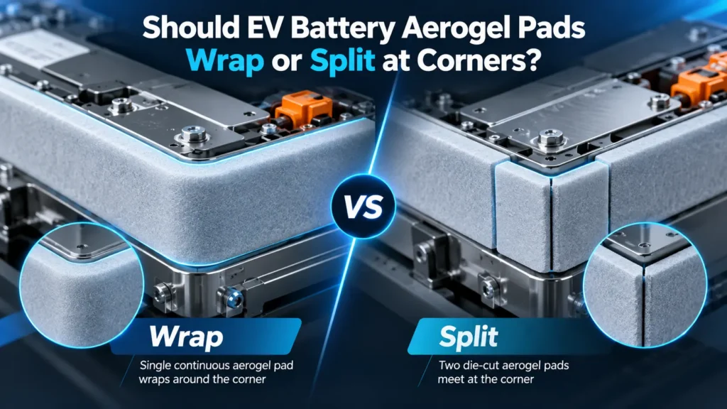
Should EV Battery Aerogel Pads Wrap or Split at Corners?
Table of Contents
An EV battery module corner may require thermal-barrier coverage across two adjacent surfaces, yet a designer can achieve that coverage with either one bent aerogel pad or several precision-cut pieces. A continuous pad eliminates an intentional joint but may introduce bending strain, springback, local creasing, or difficult placement. Segmented pads simplify certain geometries and assembly steps but create interfaces that require defined alignment and gap control. The practical question is not which drawing looks cleaner; it is which installed architecture maintains the specified barrier function through production variation and validation.
⚑ QUICK ANSWER
Why Are Battery Corners Difficult for Aerogel Barriers?
A “battery corner” may be the transition from a prismatic cell face to a shoulder, a module sidewall to its end structure, or a bracketed enclosure interface. The relevant surfaces may move relative to one another during stack compression, swelling, vibration, or assembly. Different corners therefore impose different functions and constraints. Engineering drawings should name the protected region, neighboring parts, exposure direction, mounting surfaces, required thermal coverage, and any electrical or venting exclusions.
Unlike an ideal flat panel, a corner couples curvature with finite thickness. The inside of a bend follows a shorter path than the outside; the composite may develop compression, tension, or changes in contact pressure. Access for fingers or automated placement tools may be restricted. Even a perfectly cut part can shift during installation, and a nominally closed seam can open at the tolerance extremes. Specify the installed condition rather than treating the undeformed pad outline as the final barrier.
Industry Insight 1 — Fewer seams do not guarantee better protection. A single component removes an intentional joint but does not eliminate local damage, edge lift, or loss of contact. The practical implication is to inspect the bend zone after installation and assess thermal coverage, not simply count pieces.
What Is a Continuous Wraparound Aerogel Barrier?
A continuous wraparound barrier uses one aerogel component to cover both sides of the corner. It can simplify part identification and eliminate a separate alignment operation between adjacent pads. It may also avoid a deliberate seam on a critical hot-face path. These advantages are conditional: the actual finished composite must tolerate the installed bend geometry, including any facing, adhesive carrier, release liner removal, and restraint imposed by the neighboring hardware.
Continuous does not mean strain-free. Watch for localized buckling at the inner face, cracking or fiber disruption near the outer face, corner creases, springback-driven edge lift, damaged cutouts, and installation drag. A generous nominal radius may still produce a small local effective radius if the pad contacts a sharp housing feature. Inspect the installed arc, not just the nominal CAD radius. A one-piece solution should advance only when the candidate grade and thickness have representative bend and retention evidence.
What Is a Segmented Aerogel Corner Barrier?
A segmented architecture divides the coverage into two or more discrete die-cut aerogel pads. The pieces can remain largely flat, permitting controlled placement on separate surfaces and reducing the need to force a thick or stiff composite around a transition. The architecture can also accommodate separate installation stations or subassemblies. Its key limitation is the additional interface: each seam has location, alignment, gap, handling, and retention requirements.
A segmented layout does not necessarily require overlap. Butt joints, offset joints, staggered layouts, and locally protected transition pieces can be evaluated according to space and thermal objectives. Do not assume a closed seam on a drawing stays closed after compression or under repeated movement. The design must define a measurable installed state at both nominal and worst-case assembly conditions. Each additional part also needs identification, orientation control, traceability, and mistake-proofing appropriate to the manufacturing process.
Industry Insight 2 — Additional pieces may improve assembly control while increasing interface risk. Separate pieces can reduce bending demands and improve placement access, but every added edge requires a defined inspection and retention plan. Evaluate the complete manufacturing sequence rather than the die-cutting step alone.
When Does Continuous Wrapping Make Engineering Sense?
Continuous wrapping is a credible candidate when the corner has an achievable radius, the selected grade remains intact after representative installation, and there is adequate clearance to place and retain a single pad. Favor it when an intentional seam would be difficult to inspect or would intersect a critical thermal path. The approach also benefits from stable datum features and accessible assembly tooling that can seat the entire component without dragging exposed aerogel across sharp hardware.
Before approving it, identify the bending direction and whether fiber orientation, surface facings, or asymmetric layers matter for the selected construction. Inspect representative finished pads, including holes and slots, not only blank material coupons. Record free-state and installed thickness at the corner; any localized compression or recovery should be evaluated against the actual barrier function. No universal minimum safe bend radius applies to every ceramic-fiber-reinforced aerogel grade, so require grade-specific evidence and customer-defined acceptance rules.
When Are Segmented Aerogel Pads Preferable?
Segmentation becomes attractive when a tight corner would impose unqualified strain, a sharp geometric transition prevents smooth contact, or the assembly sequence requires independent access to two mounting faces. It may also suit designs with structural brackets, large cutouts, vent pathways, or service features near the corner. Separate flat components can permit simpler material nesting, but cost and yield should be quoted from the actual drawing, chosen grade, and intended process—not inferred from part count.
The decision changes when seam control is poor. If two pads cannot be reliably located, restrained, or inspected after the module is closed, a segmented solution may produce unacceptable uncertainty despite easy die cutting. Engineers should test a representative assembly fixture and document positional repeatability. Any joint that cannot be measured directly may require indirect control through robust datums, in-process vision inspection, or controlled assembly features established with the OEM and supplier.
How Should Engineers Compare Continuous and Segmented Designs?
Use an architecture comparison that assigns requirements before scoring convenience. Thermal coverage, electrical and venting restrictions, actual installed thickness, dimensional capability, particle cleanliness, and inspection accessibility should be gates rather than discretionary preferences. After these gates are addressed, compare material utilization, installation steps, tooling, rework, and supplier process capability. A favorable concept on one dimension may be unacceptable on another; avoid averaging away a safety-critical failure mode.
Table 1 — Continuous Wrap vs. Segmented Aerogel Pads
| Design Factor | Continuous Wrap | Segmented Pads | Engineering Decision |
| Thermal coverage | No intentional joint; bend condition matters | Joint placement and gap matter | Validate assembled heat path |
| Mechanical demand | Requires grade-specific bending | Reduces bending for some layouts | Test finished-part integrity |
| Installed thickness | May crease or compress at arc | Overlap may create buildup | Measure under representative pressure |
| Placement | One item; potentially difficult routing | Multiple, potentially accessible steps | Trial actual assembly sequence |
| Retention | Control springback and edge lift | Control each piece and seam | Define inspection and aging checks |
| Manufacturing | Larger outline and nesting constraints | More items and edge length | Obtain supplier DFM and quotes |
Table 2 — Corner Geometry and Design Constraints
| Geometry Condition | Potential Problem | Design Consideration | Required Verification |
| Tight inside corner | Concentrated bend strain | Segmented or revised contour | Installed bend inspection |
| Sharp housing transition | Local abrasion or damage | Edge relief or protected contact | Representative handling trial |
| Narrow clearance | Compression or interference | Thickness budget and joint strategy | Worst-case stack build |
| Nearby vent route | Unintended obstruction | Keep-out and coverage boundary | Pack-layout design review |
| Busbar or HV interface | Electrical clearance conflict | Defined exclusion and fixation | Electrical integration review |
| Hidden assembly joint | Unverified opening | Datum and process controls | In-process inspection evidence |
Industry Insight 3 — Joint position can matter more than joint count. A seam outside the critical heat-transfer corridor may be less consequential than one seam placed directly across the target protection area. Map the local thermal exposure and plausible part movement before locating the joint.
How Should Aerogel Joints Be Positioned at Battery Corners?
Position a joint as a functional feature, not a cutting convenience. A butt joint at the exact corner can be difficult to align if both surfaces are angled or under different compression. An offset joint moves the interface to a more accessible surface but can place the opening in a different thermal exposure zone. A staggered arrangement may reduce direct line-of-sight exposure in some layered designs, while introducing material and assembly complexity. These are candidates, not universal rankings.
Annotate the seam in the assembly coordinate system. Define the supported surfaces, nominal edge location, allowable positional variation, direction of potential movement, and method for checking the finished joint. Consider whether the seam is exposed to a hot gas jet, conductive support, or sensitive electrical component. A nominal butt gap of zero does not mean that every assembly produces zero opening. Evaluate both manufacturing tolerances and the thermal consequence of the resulting gap distribution.
Table 3 — Joint Design Options
| Joint Configuration | Possible Advantage | Main Limitation | Validation Focus |
| Direct-corner butt joint | Minimal nominal thickness buildup | Hard to align around curvature | Worst-case joint opening |
| Offset butt joint | Accessible location away from arc | May shift exposure zone | Local heat-flow path |
| Overlap joint | May sustain coverage under variation | Thickness and compression buildup | Interference and thermal testing |
| Staggered layered joint | May interrupt a direct gap path | Added layers and assembly work | Installed geometry repeatability |
| Separate corner piece | Can isolate transition geometry | More edges and retention needs | Piece migration and joint control |
How Can Engineers Prevent Thermal Coverage Gaps?
Distinguish nominal CAD coverage from assembled coverage. Nominal outlines omit pad placement error, die-cut variation, module datum drift, compression-induced movement, adhesive positioning, and surface mismatch. The gap question is therefore a tolerance-chain question. Identify the edges that define the thermal opening, construct a worst-case or statistically justified stack-up, then assess whether the resulting installed configuration still meets the customer’s barrier requirement.
Record both intended minimum coverage and the maximum credible uncovered region under the defined build conditions. If the drawing specifies a gap, identify its datum, measurement state, and inspection method. Do not use an arbitrary universal maximum acceptable gap: allowable geometry depends on source temperature distribution, adjacent hardware, material construction, exposure duration, and the battery platform’s thermal safety objectives. Use representative prototypes and risk-based testing to determine project acceptance, especially when the seam lies on a critical thermal pathway.
Can Overlapping Aerogel Pads Improve Corner Coverage?
Overlap can sometimes accommodate placement variation, but it trades a seam opening risk for a local thickness and force-management challenge. Two nominal thicknesses cannot simply be added to predict installed height: compressibility, pressure, coating thickness, and construction affect the measured result. A thick overlap may distort the module, interfere with an adjacent bracket, or increase local contact forces. Conversely, a poorly constrained overlap can slide and expose an edge after cycling.
Treat overlap as an engineered configuration with a measured assembly state. Define which piece goes over the other, where the overlap ends, how the edges are secured, and how the stack affects contact and thermal pathways. Test likely extremes of placement and compression. If a butt joint provides adequate validated performance within available clearance, overlap offers no automatic advantage. A staggered layout should receive the same scrutiny rather than being treated as intrinsically protective.
Industry Insight 4 — Overlap is a thickness-and-clearance trade-off. Extra nominal coverage may consume stack space and change adjacent part loads. Require installed-thickness and interference evidence before giving overlap preference in a design review.

How Do Thickness, Compression, and Tolerances Affect Corner Design?
Distinguish material nominal thickness, measured free-state thickness, and installed thickness under representative constraint. Ceramic-fiber aerogel composites are not necessarily rigid spacers; loading pressure and measurement method influence results. A bend can redistribute material locally, while a seam can produce an abrupt transition between covered and uncovered regions. Tooling and assembly specifications should define the thickness measurement force or method, measurement locations, and recovery or relaxation interval where applicable.
The tolerance chain must account for material and converted-part dimensions, assembly datums, fixture positioning, adhesive or facing layers, module hardware, and relevant cell expansion states. Analyze more than an ideal room-temperature installation. Thermal aging, humidity exposure where applicable, and compression history may affect positioning and fit, but the magnitude must be demonstrated for the actual construction. Release drawings only after the tolerance assumptions and inspection capabilities have been reviewed with the integrator and supplier.
Table 4 — Thickness, Clearance, and Tolerance Risks
| Design Variable | Potential Effect | Control Method | Inspection Requirement |
| Felt thickness | Gap or interference variation | Grade-specific thickness specification | Defined contact pressure |
| Bend-zone thickness | Crease or local thinning | Controlled installed curvature | Local thickness map |
| Overlap buildup | Assembly force change | Defined overlap construction | As-built stack measurement |
| Die-cut edge location | Joint opening variation | Datum-based tolerance drawing | Finished-part profile inspection |
| Adhesive/facing | Asymmetric bending response | Approved finished construction | Interface and peel checks |
| Pad placement | Lost intended coverage | Locators and work instructions | Joint photographs or gauges |
How Do Facings, Adhesives, and Retention Change the Architecture?
A bare felt coupon and a laminated finished component can bend differently. Protective facings may add stiffness, alter friction during placement, or bridge a small surface crack; adhesives may restrict sliding or create peel loading at the arc. These effects should be verified for the selected facing, adhesive, substrate, temperature history, and surface preparation. An adhesive label by itself does not establish long-term retention, nor does a smooth-looking outer facing prove the aerogel beneath is undamaged.
For continuous pads, retention must resist springback, edge lift, and misrouting. For segments, it must preserve each edge location and the intended joint relation. Decide whether the fixture, adhesive, mechanical feature, or stack compression supplies positional control, and identify which condition continues after service exposure. Verify retention without obstructing ventilation, electrical clearances, coolant paths, or disassembly access. Where released particles are a concern, handle both candidates with a project-specific cleanliness check rather than assuming more cuts always mean more contamination.
How Should Vent Paths and Electrical Clearances Be Protected?
A thermal barrier is one layer of pack protection, not authorization to cover nearby functionality. Before detailing an aerogel corner, mark cell vents, gas-routing corridors, busbars, live terminals, cooling interfaces, pressure-relief features, and tooling access zones in the 3D assembly. These restrictions may eliminate an otherwise convenient wrap path or force a seam to move. The required electrical clearances depend on the actual voltage architecture, environment, applicable requirements, and validated insulating system; do not substitute a generic distance.
Joint and retention changes should trigger cross-functional review. A newly added adhesive tab, overlapped edge, or corner piece may encroach on a vent or inspection opening that the previous layout preserved. If the aerogel is being asked to provide dielectric as well as thermal function, specify and independently verify each duty. Do not infer battery-level abuse-test success from a thermal conductivity value, a bending coupon, or one visually successful prototype.
How Do Precision Die Cutting and Assembly Sequence Affect DFM?
Material utilization is only one manufacturing metric. Continuous outlines can require larger blank dimensions, awkward nesting, or fragile narrow bridges. Segmented pieces may nest efficiently but increase edge length, pick-and-place operations, handling exposure, item tracking, and placement checks. Holes, slots, internal corners, and small tabs can become crack initiators or difficult-to-control features, especially when they coincide with a required bend. A supplier DFM review should distinguish what is geometrically possible from what is stable in serial production.
Define the installation order before selecting the architecture. Can a one-piece pad pass between adjacent components without scraping? Must one segment be applied before the module is closed? Which surface serves as the placement datum? Is joint inspection possible before the next station blocks access? Compare prototypes made by representative production-intent cutting and handling methods. Use actual material yield, cycle-time, scrap, and process-capability evidence from supplier trials; do not claim a generic cost winner.
Industry Insight 5 — The finished geometry determines manufacturability. A material can be cut as a simple sheet yet fail at an intricate corner component with narrow sections or challenging handling. Supplier feasibility must be demonstrated on revision-controlled drawings and intended production materials.
Table 5 — Manufacturing and Assembly Comparison
| Evaluation Area | Continuous Architecture | Segmented Architecture | Supplier / OEM Input |
| Material nesting | Potential larger blank | Potential smaller nested parts | Quoted yield by revision |
| Cutting features | Bend-adjacent details may be sensitive | More exposed cut edges | Feature capability review |
| Handling | One flexible shape | Multiple identified shapes | Particle and damage controls |
| Assembly time | Fewer picks, complex routing | More picks, potentially simple placement | Time study at target station |
| Quality checks | Bend/fit inspection | Seam/position inspection | Inspection access and gauges |
| Traceability | Single finished item | Multi-piece set control | Lot and set identification |
How Should Engineers Validate the Selected Corner Design?
Validate the full chain: candidate material, converted component, installed geometry, and resulting thermal function. Begin with grade-specific material data and relevant flex or damage screening. Then test finished shapes at representative radii, orientations, compression states, and mounting conditions. Photograph any bend damage, gap, edge lift, delamination, or shifts after handling. For segmented candidates, measure joint location and opening at nominal and tolerance-extreme installation states. Conduct repeatability trials with the intended assembly process, not only careful laboratory placement.
Thermal screening may include guarded comparisons of specimens and assembly-level heat-flow or temperature measurements that reflect the critical transfer path. ASTM C518 and ISO 8301 address steady-state heat-transfer measurements for flat slabs; their outputs do not automatically qualify a curved, jointed battery assembly. Battery-level thermal-runaway and abuse-test acceptance must be set by the OEM system-validation plan. Where relevant, add vibration, aging, swelling/compression, cleanliness, and retention exposures. Compare both architectures against the same acceptance criteria and preserve test uncertainty and sample traceability.
Industry Insight 6 — Installed performance is the final decision basis. A passing material datasheet and an attractive CAD rendering are necessary inputs but not substitute evidence for the completed assembly. Approve the architecture only after representative build and functional verification.
Practical Hypothetical Engineering Example: One Corner, Three Concepts
Consider a hypothetical prismatic battery module with a curved transition between a side region and an adjacent bracket face. The OEM needs continuous thermal-barrier coverage but has an interference-sensitive hardware corridor and limited installation access. The engineering team compares Concept A, a one-piece wrap; Concept B, two flat pads with an offset butt joint; and Concept C, a main pad plus a separately located corner piece. No numerical result or vendor process capability is assumed in this example.
First, create a shared 3D clearance and keep-out model; record the candidate aerogel grade, actual thickness, facing construction, critical thermal corridor, and installation order. Build Concept A using the final pad outline and inspect the arc for creases, springback, cutout damage, and edge lift. For Concept B, place the seam at an accessible datum and quantify positional variation and worst-case opening. For Concept C, verify the corner piece does not migrate or add unacceptable thickness. In each case document prototype part identification, drawings, joint photographs, installed-thickness measurements, and deviations.
Next, screen feasible assemblies against the same mechanical and thermal requirements. A concept failing a vent clearance is rejected before thermal testing regardless of its apparent coverage. A concept with an intact wrap but unacceptable retention is redesigned or rejected. A segmented concept is not rejected simply because a joint exists; the joint’s actual behavior and thermal consequence determine suitability. Complete the decision by comparing the validated architectures for production repeatability, inspection access, and supplier DFM risk. Release one architecture only after the responsible customer team approves the evidence package.

Design Decision Matrix: When to Wrap, When to Split, and When to Rework
Use the following sequence as a review gate rather than a universal ranking. First reject any concept that violates a mandatory keep-out, electrical interface, or thermal coverage requirement. Second test whether the finished aerogel construction can be installed without unacceptable bend damage or interference. Third evaluate seam location, joint opening, overlap, and retention under the combined dimensional extremes. Fourth demonstrate manufacturing and assembly repeatability, including inspection access. Fifth require customer-defined thermal-function validation and document residual risk. If neither wrap nor split meets the gates, redesign the corner geometry, mounting scheme, or material construction rather than forcing a binary choice.
Table 6 — Corner Barrier Qualification and RFQ
| Requirement | Customer Input | Supplier Evidence | Acceptance Decision |
| Coverage function | Critical surface and thermal target | As-built photos and test plan | OEM-defined performance gate |
| Material grade | Grade, thickness, facing | Controlled material identification | Approved candidate only |
| Corner fit | Radius, clearance, install method | Representative prototype measurements | No prohibited interference |
| Seam or overlap | Position and allowed state | Worst-case joint inspection | Project-specific gap rule |
| Retention | Movement and aging exposure | Location checks after exposure | Meets positional criteria |
| Thermal qualification | Test envelope and failure limits | Material and assembly test record | Customer validation sign-off |
| Production control | Drawing and inspection plan | DFM, sampling, lot records | Supplier quality approval |
Common Engineering Mistakes in Aerogel Corner Design
- Assuming every felt grade can follow a tight corner. Verify the actual composite and installed geometry.
- Selecting one piece solely to reduce part count. Account for bend integrity and placement repeatability.
- Splitting the barrier without locating the seam. Put joint coordinates and datums on the drawing.
- Approving nominal CAD coverage as real coverage. Review worst-case assembled states.
- Ignoring grade-specific construction. Different facings, fibers, and adhesives may change response.
- Confusing free thickness with installed thickness. Define compression and measurement pressure.
- Assuming an overlap improves thermal protection. Check interference and contact conditions.
- Omitting the tolerance chain. Include material, cutting, positioning, and hardware variation.
- Calling a nominal butt joint gap-free. Inspect installed edge separation.
- Treating adhesive as a complete retention qualification. Test after relevant exposures.
- Leaving assembly order until manufacturing launch. Simulate realistic routing and handling early.
- Ignoring vent or high-voltage keep-outs. Obtain battery integration approval.
- Using raw-sheet bend evidence for a converted part. Include holes, slots, edges, and facings.
- Optimizing only sheet utilization. Compare inspection, pick count, scrap, and process control.
- Treating one successful prototype as battery qualification. Require sample traceability and functional testing.
Engineering Checklist for Aerogel Corner Barrier Design
- Application and duty: Identify battery location, protected region, thermal target, and relevant module-level validation.
- Material and construction: Record grade, nominal and measured thickness, fiber orientation if relevant, facings, adhesives, and batch information.
- Corner geometry: Define 3D surfaces, radius convention, mounting datums, critical cutouts, and adjacent hardware.
- Installed package: Specify free versus installed thickness, compression, available clearance, and worst-case stack-up.
- Architecture concepts: Review wrap, segmented, and optional hybrid options under identical functional requirements.
- Joint management: Identify location, type, nominal state, allowed gap or overlap, movement direction, and inspection method.
- Process controls: Specify die-cut feasibility, cut-edge quality, handling, sequence, positioning, and retention.
- Interfaces: Verify vent paths, busbars, high-voltage spacing, coolant hardware, and service access.
- Evidence: Request representative fit trials, damage checks, installed-joint measurements, retention tests, and thermal validation.
- Release: Document OEM acceptance, drawing revision, lot traceability, change control, and supplier quality records.
RFQ Checklist for Custom Aerogel Corner Barriers
A technically actionable RFQ should include the installation location and intended function; a PDF plus DXF/DWG drawing and 3D assembly model where available; material grade or candidate grades; nominal and installed thickness expectations; corner geometry and reference radii; preliminary wrap or split concepts; piece count and seam coordinates; gap, overlap, and clearance requirements; surface facing and adhesive needs; retention method; vent and electrical keep-outs; critical holes or slots; material handling and cleanliness criteria; prototype quantities; annual demand; drawing revision; inspection requirements; and the customer’s thermal validation and reporting plan.
If the architecture is undecided, transmit the assembly geometry, material requirements, thermal coverage boundary, and manufacturing constraints, then ask for a documented material/DFM comparison before asking for a production quote. Request separate pricing or feasibility comments for concepts where practical. Distinguish supplier-provided manufacturing evidence from OEM-owned pack-level performance acceptance.
How Boost Insulation Supports Custom Aerogel Corner Barriers
Boost Insulation provides an aerogel insulation product category and describes drawing-based consultation, prototype development, and precision die-cut tooling on its aerogel insulation product page. These published capabilities make an early material-and-geometry DFM discussion relevant, but they do not establish that any specific grade, corner radius, tolerance, laminate, or customer requirement has already been qualified. Ask Boost to confirm grade-specific data, available conversion routes, critical feature feasibility, sample inspection, and proposed documentation against your current drawing.
For broader context, Boost’s EV aerogel selection guide explains upstream material decisions; its prismatic-cell article describes application integration; and its pad-retention guide treats movement control. Its module end-plate article addresses a neighboring interface, while the cell-to-cell material overview supplies general background. This article is distinct: it defines a decision path for the corner architecture and its joints.
Frequently Asked Questions
1. Should EV battery aerogel pads wrap or split at corners?
Choose based on installed geometry and evidence, not on a blanket preference for fewer pieces. A continuous wrap may avoid a joint but introduces bending and retention requirements; segmented pads can simplify placement but introduce seams. Both need a defined thermal coverage target, clearance review, inspection access, and assembly-level verification. Select the architecture that satisfies the customer’s acceptance criteria with repeatable manufacturing and installation controls.
2. Can ceramic-fiber aerogel bend around tight battery corners?
Some reinforced aerogel constructions can tolerate the curvature required by a particular assembly, but there is no universal safe minimum bend radius for every ceramic-fiber aerogel grade. Thickness, backing, facing, fiber network, handling direction, and installation constraints can change damage behavior. Verify the selected finished component using a representative fixture and then inspect for cracking, local thinning, creases, particle release, and post-installation fit.
3. When should engineers choose segmented aerogel pads?
Segmentation is worth evaluating when a one-piece pad cannot be routed into place, when the installed radius is too demanding for the candidate grade, or when separate mounting faces need independent alignment. It can also help with complex cutouts and production-intent flat-part converting. However, segmentation is suitable only when seam geometry, placement variation, retention, inspection, and relevant thermal performance can be demonstrated on actual assemblies.
4. Do seams between aerogel pads create thermal gaps?
A seam creates a potential discontinuity, but the presence of a seam is not itself a quantified thermal failure. Its effect depends on actual opening, joint location, contact conditions, facing materials, and the local heat-transfer path. Review nominal and tolerance-extreme assembled states, check potential movement over the required exposures, and validate the customer-defined thermal outcome. Do not assume either perfect continuity or unavoidable failure based on seam appearance alone.
5. Is overlapping aerogel better than a butt joint?
Not inherently. Overlap may reduce the chance of a direct uncovered line under some placement variations, but it adds local thickness and can change pressure, contact, and assembly interference. A controlled butt joint may fit the package more reliably. Compare both configurations using measured installed thickness, worst-case edge positions, retention behavior, and application-relevant thermal tests; do not assign a universal best seam geometry.
6. How does aerogel thickness affect corner installation?
Thickness influences the strain distribution through a bend, available corner clearance, compression under mounting force, and any overlap buildup. Free-state nominal thickness is not always equal to the thickness in the assembled pack, especially for compressible constructions. Specify measurement conditions and document local thickness at the corner and joint. Use grade-specific evidence rather than extrapolating suitability from a generic thickness range or material datasheet.
7. How should engineers validate an aerogel corner barrier?
Start with the safety function and acceptance target, then validate the actual material grade and finished geometry. Check corner fit, cracks, creasing, particle release where relevant, seam openings, installed thickness, assembly repeatability, and retention after representative exposures. Apply thermal tests appropriate to the battery’s critical path, distinguishing flat-specimen conductivity measurements from assembled-barrier performance. OEM-level pack validation remains separate from component screening and supplier quality approval.
8. What should buyers specify for custom die-cut aerogel corner pads?
Provide revision-controlled 2D drawings and a 3D installation view, candidate aerogel grade and thickness, the protected thermal region, available clearance, vent and electrical exclusions, and expected assembly sequence. Identify candidate wrap or segmented layouts, joint coordinates, gap and overlap requirements, facings, adhesives, retention, prototype quantity, forecast demand, and inspection criteria. Request a documented DFM response and a mutually agreed plan for functional validation and lot traceability.
Request a DFM Review for Custom Aerogel Corner Barriers
For an OEM or Tier 1 corner-insulation review, send Boost Insulation the current component drawing, 3D corner geometry, candidate aerogel grade and thickness, proposed wrap or segmented scheme, joint and clearance constraints, adhesive or facing requirements, critical cutouts, retention expectations, prototype quantities, annual volume, and the inspection and thermal-validation targets. Request confirmation of material feasibility, conversion options, test specimens, drawing-dependent DFM risks, and prototype documentation before committing to production tooling. The next step is Corner Geometry + Aerogel Requirements + Drawing → Material/DFM Review → Prototype Request. No supplier drawing review replaces the customer’s system qualification.
Related Posts:

How Does Mica Prevent Dielectric Breakdown in EV Batteries?
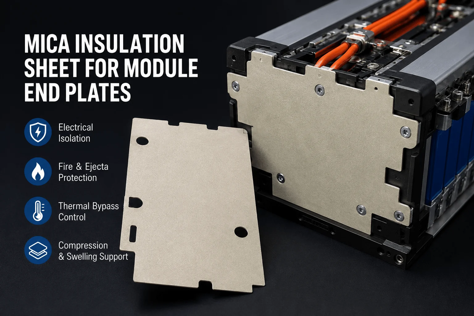
How Is a Mica Insulation Sheet Used on Module End Plates?
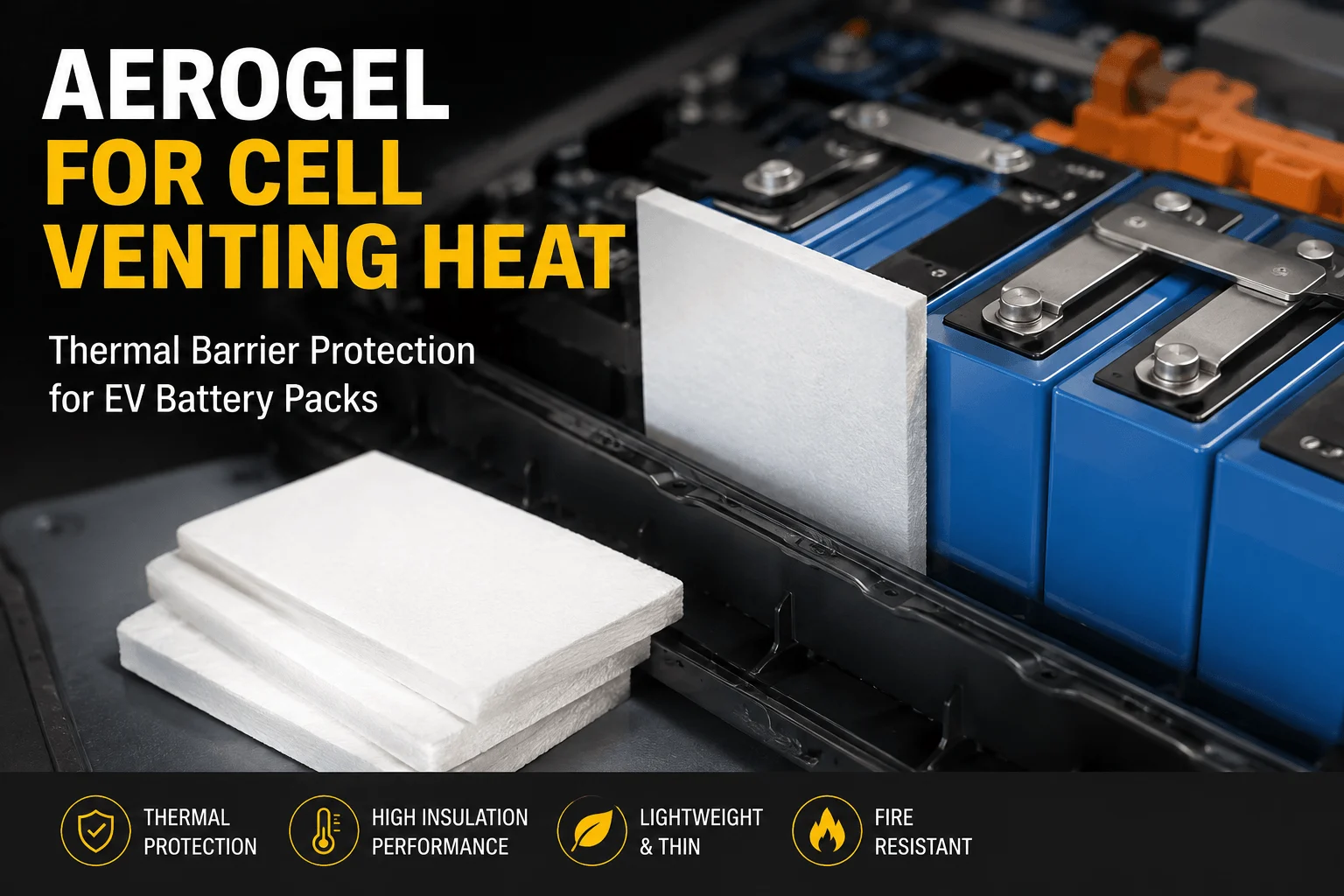
How Does Aerogel Handle Cell Venting Heat in EV Packs?

How Does FR4 Insulate EV Battery Busbars?
How Do You Test Silicone Foam Recovery in EV Battery Pads?
Is a Mica Insulation Sheet Better Than Aerogel for EVs?
 root
