How Is Aerogel Used Between Prismatic EV Battery Cells?
How much protection can fit into the narrow gap between two high-energy prismatic cells? That small interface has to manage normal cell movement for years, yet it may also become the first line of defense when one cell enters thermal runaway. This is why aerogel is increasingly specified as a cell-to-cell barrier: it adds high thermal resistance without consuming the pack space demanded by bulky insulation.
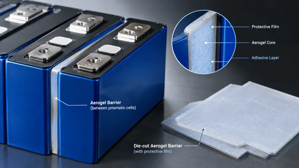
Aerogel between prismatic EV battery cells is used as a thin, die-cut cell-to-cell thermal barrier that covers most of the large cell face. It increases thermal resistance between adjacent cells, helps delay heat transfer during thermal runaway, and, when the selected construction is mechanically compliant, can also accommodate cell swelling and compression. Production parts are often laminated or encapsulated with protective films and may include selective adhesive for fast module assembly.
What Does Aerogel Do Between Prismatic Battery Cells?
In a prismatic EV battery module, the broad faces of neighboring cells are usually packed close together. That geometry is efficient for energy density, but it also creates a large contact area through which heat can move from one cell to the next. A cell-to-cell aerogel barrier adds thermal resistance directly at this interface. In normal operation, it reduces unwanted heat exchange between neighboring cells. During an abnormal event, it slows the rate at which a hot or failing cell transfers thermal energy into the adjacent cell.
The key word is slows. Aerogel is not a magic material that makes the rest of the battery pack irrelevant. Thermal runaway propagation can also move through busbars, module frames, cooling plates, fasteners, hot vent gases, radiation, and other structural paths. A good battery safety design therefore treats the intercell barrier as one layer of a system-level propagation strategy. The barrier protects the most direct face-to-face path, while pack architecture, vent routing, cooling design, electrical protection, and enclosure fire protection address the remaining paths.
For prismatic cells, an aerogel part may perform three functions at the same time: thermal insulation, controlled mechanical compliance, and electrical separation. However, these functions must be verified for the complete part, not assumed from the word aerogel. The aerogel core, reinforcement, encapsulation film, adhesive, edge seal, compression state, and cut geometry all influence final performance.
Where Is the Aerogel Barrier Installed?
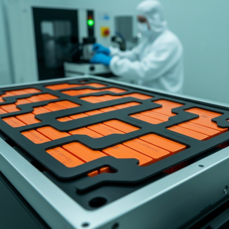
The most common location is between the large flat faces of adjacent prismatic cells. The die-cut part is normally shaped to cover as much active face area as the mechanical design allows, while avoiding terminals, vent features, alignment structures, sensing components, or other keep-out zones. In a conventional module, a barrier can be placed between every cell, between selected cell groups, or in a repeating stack together with compression pads and structural spacers. In cell-to-pack or cell-to-chassis architectures, the exact arrangement changes, but the same principle applies: place thermal resistance where a runaway cell would otherwise couple strongly to its neighbor.
Coverage matters. A barrier with unnecessary windows, deep notches, or narrow necks can create thermal bypass areas. At the same time, a part that ignores the cell vent, edge radius, busbar clearance, or assembly datum may wrinkle, shift, or interfere with module build. For that reason, the correct part shape is not simply a rectangle copied from the cell datasheet. It is a DFM problem that must combine thermal coverage, mechanical fit, tolerance stack-up, and assembly sequence.
How Does Aerogel Slow Heat Transfer During Thermal Runaway?
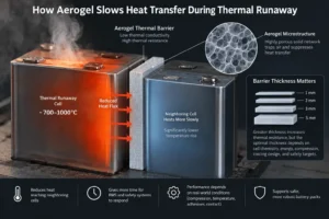
Silica-based aerogel composites contain a highly porous solid network that suppresses heat transfer through the material. In a thin cell-to-cell format, that low conductivity creates a high through-plane thermal resistance relative to many conventional polymer foams. When one prismatic cell becomes extremely hot, the barrier reduces the heat flux reaching the neighboring cell face. The neighboring cell therefore heats more slowly, which can increase the time available for the battery management system, venting strategy, pack enclosure, and other protective features to control the event.
A simple engineering relationship is useful: through-plane thermal resistance increases with thickness and decreases with thermal conductivity. But real battery barriers do not behave like an ideal, uncompressed laboratory coupon. Compression changes thickness and contact conditions. Temperature changes material properties. Adhesive layers and protective films add parallel or series heat-transfer effects. Edge contact can create a bypass path. This is why engineers should request thermal data at relevant temperature and compression states instead of selecting a barrier only from a room-temperature conductivity value.
Recent experimental work on large-format prismatic lithium-ion batteries has specifically studied aerogel thermal barriers with different thicknesses, including 1, 2, 3, and 5 mm constructions. The broader engineering lesson is more important than any single test number: barrier thickness materially affects propagation behavior, but the optimum thickness must be determined together with cell chemistry, cell energy, state of charge, available gap, preload, cooling architecture, and the required safety target.
Why Are Prismatic Cells a Strong Application for Aerogel?
Prismatic cells create an unusually clear use case for thin intercell insulation. They have large, relatively flat sidewalls and are assembled in tight stacks, so a sheet-based barrier can intercept a large percentage of the direct cell-to-cell heat path. At the same time, every millimeter of added spacing can multiply across a long row of cells and reduce volumetric efficiency. This pushes designers toward materials that deliver useful thermal resistance in a thin section.
Large-format prismatic cells also store substantial energy in each individual unit. Chemistry matters: an LFP cell and a high-nickel NMC cell do not produce the same thermal runaway profile, and state of charge can significantly change event severity. Nevertheless, ‘safer chemistry’ should not be interpreted as ‘no propagation risk.’ Modern pack programs increasingly evaluate the entire failure scenario, including cell venting, heat transfer, smoke management, structural integrity, and the possibility that one failed cell can heat its neighbors.
The shift toward cell-to-pack and cell-to-body architectures makes this interface even more strategically important. Removing intermediate module structures can improve energy density and cost, but it also means engineers have fewer redundant layers available to absorb heat or isolate a failed cell. In these designs, a thin, precisely converted cell barrier can become a high-value component because it protects safety while consuming little packaging volume.
Is Aerogel Only Thermal Insulation, or Can It Also Act as a Compression Pad?
It can do both, but only if the material construction is designed and validated for both jobs. Prismatic cells change dimension during charge and discharge, and they can swell as they age. The module stack therefore needs controlled pressure: too little restraint can allow movement and poor interface control, while excessive pressure can accelerate mechanical damage or distort cells. Some reinforced aerogel barriers are engineered to provide resilient compression behavior while maintaining thermal resistance.
This is a critical procurement distinction. A generic industrial aerogel blanket may have excellent insulation performance yet be unsuitable as a controlled compression component. For battery use, the relevant data include stress-strain behavior, compression set, rebound, fatigue after repeated cycling, thickness tolerance, and performance at end-of-life compression. Engineers should define the target pressure window and compressed thickness rather than asking a converter only for nominal uncompressed thickness.
Engineering insight: qualify the barrier at the compressed condition it will actually see in the module, especially at end of life. A material that looks excellent as a free-standing coupon can behave very differently after years of stack pressure and cell swelling.
What Does a Production-Ready Aerogel Cell Barrier Look Like?
A production part is often more complex than a bare aerogel sheet. Depending on the battery design, the stack-up can include a reinforced aerogel core, protective PET or polyimide film, flame-resistant film, pressure-sensitive adhesive, spacer frame, foam edge, mica layer, or other functional layers. Encapsulation is especially important when the selected aerogel is dusty or mechanically fragile. A protective film can improve handling, reduce particle shedding, and create a cleaner surface for automated assembly.
The right construction depends on the priority of the project. A minimal stack may be chosen for low thickness and low mass. A framed construction may be selected to control compression and protect the aerogel edge. Selective adhesive can simplify placement without locking the entire cell face into a rigid laminate. A hybrid aerogel-mica design may be considered when the program needs both very low heat transfer and a more rigid high-temperature shield. There is no universal best stack-up; there is only a stack-up optimized for the cell, pack, test method, and assembly process.
For high-volume EV production, the part also has to survive logistics and line handling. The liner must release consistently. The adhesive cannot lift at corners. The film cannot shrink enough to expose aerogel. Edges cannot shed excessive particles. The part has to register correctly against cell or fixture datums, and the release-liner design must work with manual or automated placement. These manufacturing details do not appear in a thermal simulation, but they often determine whether a concept can be industrialized.
How Thick Should Aerogel Be Between Prismatic EV Battery Cells?
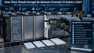
There is no single correct thickness. In practical EV battery designs, the barrier thickness is constrained by available cell pitch, required thermal delay, mechanical preload, cell swelling allowance, and total pack energy density. A thicker barrier can increase through-plane thermal resistance, but it also consumes stack length and may change compression behavior. A thinner barrier preserves packaging space but leaves less margin for thermal protection and manufacturing variation.
The better design question is: what compressed thickness provides the required thermal and mechanical performance at the module conditions that matter? That condition should include beginning of life, expected state of charge, normal operating temperature, end-of-life swelling, and the target thermal runaway test. When space is tight, small changes in material grade, reinforcement, encapsulation, or hybrid stack-up can sometimes deliver more value than simply increasing nominal thickness.
Tolerance also becomes a system issue. If a module contains dozens of intercell parts, thickness variation accumulates across the stack. A converter should therefore control not only the X-Y outline but also material caliper, lamination thickness, adhesive coating, and local edge build-up. For a cell stack, consistent Z-direction thickness can be just as important as a clean die-cut profile.
Nine Engineering Parameters to Specify Before You Order
- Cell geometry and usable coverage area. Provide the prismatic cell width, height, corner radii, vent location, terminal keep-outs, busbar clearances, and assembly datums.
- Cell chemistry, capacity, and target state of charge. LFP, NMC, LMFP, and other chemistries can produce different heat-release and venting behavior. The barrier must be selected against the actual cell hazard profile.
- Nominal and compressed thickness. Define both the incoming part thickness and the intended installed thickness under stack pressure.
- Compression behavior over life. Specify the required pressure window, compression set, rebound, and expected cell swelling or module growth.
- Thermal performance at relevant conditions. Ask for conductivity or thermal resistance data at realistic temperatures and compression, plus any hot-side/cold-side or torch/propagation test data relevant to the design.
- Electrical insulation requirements. If dielectric isolation is part of the function, define dielectric strength, insulation resistance, creepage/clearance constraints, and the effect of film seams or exposed edges.
- Flame and high-temperature requirements. State the required material flammability rating or internal OEM specification, and distinguish normal service temperature from short-duration thermal runaway exposure.
- Environmental and durability requirements. Include humidity, thermal cycling, vibration, chemical exposure, electrolyte contact risk, adhesive aging, and shelf-life expectations.
- Manufacturing and quality requirements. Define dimensional tolerances, cleanliness, particle control, liner design, packaging, lot traceability, PPAP/APQP expectations, and annual volume.
Aerogel vs. Mica vs. Foam Between Prismatic Cells
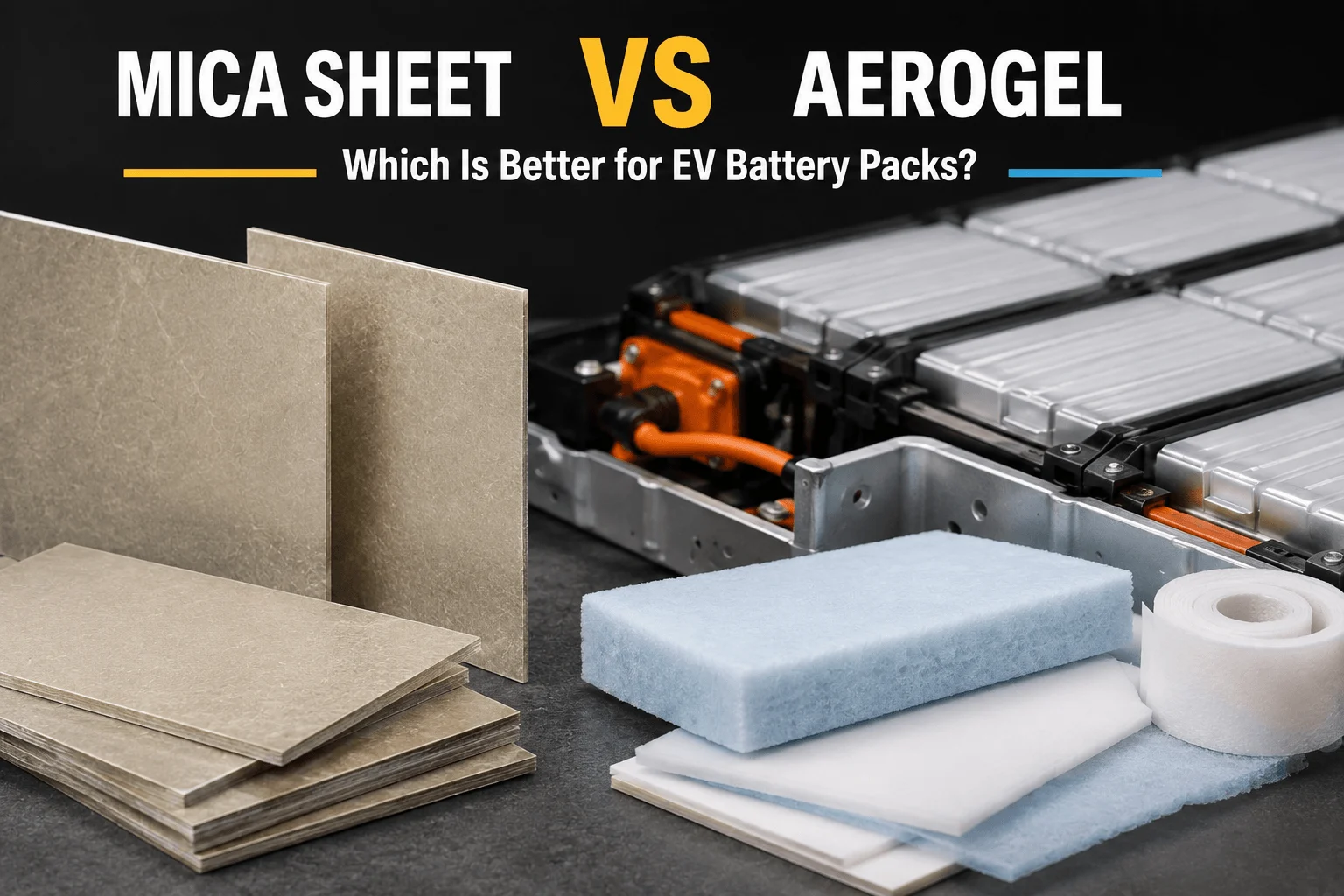
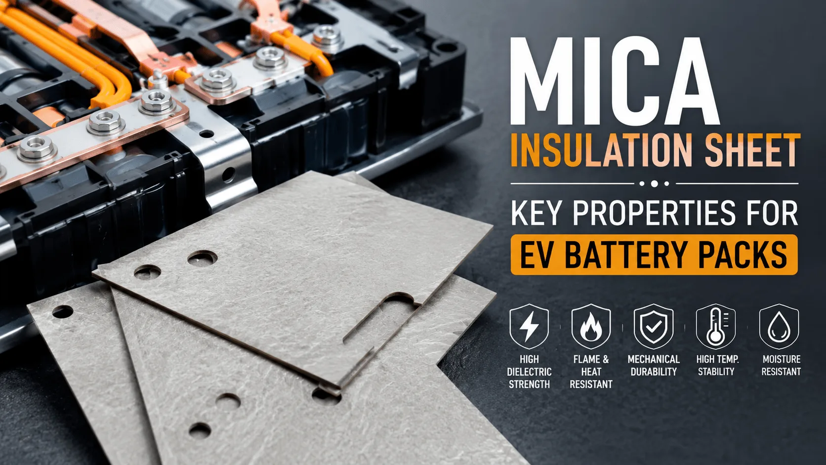
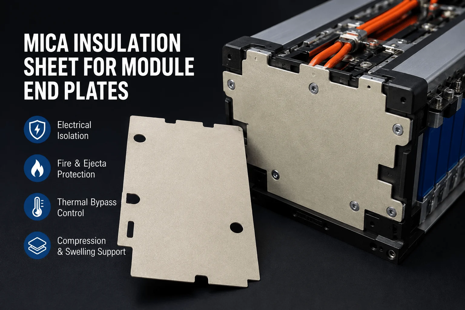
Battery engineers often compare aerogel with mica and foam, but these materials do not perform identical jobs. Aerogel is attractive when the design needs high thermal resistance in a thin, lightweight interface. Mica is valued for electrical insulation, rigidity, flame resistance, and high-temperature shielding. Silicone or polyurethane foams are widely used for cushioning and compression management, but their thermal protection during a severe runaway event may be limited compared with high-temperature inorganic insulation.
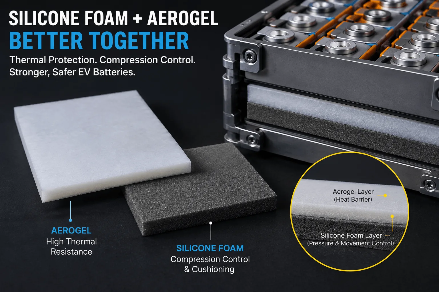
The practical answer is frequently a hybrid. An aerogel layer can be paired with a film for cleanliness and dielectric control, a foam frame for compression management, or a mica layer for added flame and erosion resistance. Hybridization can also help tune cost: instead of over-specifying an expensive material across the entire part, the engineer can place each material only where its function is needed.
| Material | Primary strength | Typical limitation | Best use in stack-up |
| Aerogel composite | Very high thermal resistance at low thickness and mass | Can be fragile, dusty, or compression-sensitive depending on grade | Cell-to-cell thermal barrier; hybrid compression/thermal pad |
| Mica | Dielectric strength, rigidity, flame and high-temperature shielding | Less compliant; may consume more mass or space for equivalent thermal delay | Rigid fire/electrical barrier; hybrid layer |
| Silicone / PU foam | Compression control, cushioning, vibration management | Usually lower severe-event thermal protection than inorganic barriers | Mechanical spacer or compression layer |
| Hybrid laminate | Combines thermal, mechanical, dielectric, and assembly functions | More complex converting and validation | High-performance EV programs with multiple requirements |
What Makes Aerogel Difficult to Die-Cut and Laminate?
Aerogel conversion is different from ordinary film die-cutting. Many aerogel sheets are porous, compressible, fibrous, or prone to edge damage. Excessive die pressure can crush the local structure and create thickness variation. Poor tooling can generate ragged edges, dust, or delamination. If a protective film is laminated too aggressively, the process can alter the intended compression behavior. If the adhesive pattern is not controlled, squeeze-out or edge lift can interfere with assembly.
For repeatable production, the converter has to control material handling from incoming inspection through slitting, lamination, die-cutting, liner removal, visual inspection, and packaging. Clean manufacturing is especially valuable around battery components because conductive particle contamination is unacceptable. Tooling strategy should also match geometry and volume. CNC cutting is useful for early prototypes and rapid design changes, while precision die-cut or rotary processes are better suited to high-volume repeatability once the design is frozen.
Boost Insulation positions its EV battery manufacturing around in-house DFM, CNC and precision die-cutting, lamination, controlled cleanroom production, automotive quality systems, and rapid prototyping. For an aerogel cell barrier, those capabilities matter because the buyer is not only purchasing raw material; the buyer is purchasing a finished functional component whose geometry, stack-up, cleanliness, and consistency must match an EV production process.
How Should You Design an Aerogel Barrier for Easier Assembly?
Start with the cell and the assembly process, not with the cutting tool. Maximize useful thermal coverage but preserve intentional clearances around vents, terminals, locating features, adhesive squeeze zones, and electrical components. Avoid small unsupported tabs that can fold during liner removal. Use generous internal radii where possible because sharp re-entrant corners can become weak points in fragile laminates. If a part needs a pull tab, make sure it does not become a heat bridge or interfere with busbar installation.
Adhesive should be treated as a functional layer. Full-surface adhesive can improve handling but may restrict compliance or change thermal contact. Perimeter or selective adhesive can preserve central compressibility while locating the part during stack assembly. The correct pattern depends on the cell surface, compression method, assembly direction, and whether the part is expected to move as the cell breathes.
Also plan the release liner. A theoretically perfect barrier can still create line stoppages if operators cannot peel it quickly, if the liner tears, or if automated equipment cannot pick the part reliably. For high-volume programs, ask for kiss-cut presentation, liner tabs, roll or sheet format, orientation marks, and packaging that matches the customer’s workstation. These details convert a material specification into a production-ready component.
How Should Aerogel Cell-to-Cell Barriers Be Tested?
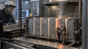
Qualification should move from material data to part data and finally to module or pack data. At the material level, useful checks include thickness, density, thermal conductivity or thermal resistance, compression stress-strain behavior, dielectric properties, flammability, and environmental aging. At the converted-part level, verify dimensions, edge quality, lamination integrity, adhesive peel, particle shedding, and thickness after lamination.
The most important evidence comes from representative thermal abuse testing. A hot-plate or torch test can be useful for screening, but it is not the same as a real cell thermal runaway event. Cell-level or mini-module propagation tests are better for determining whether the selected barrier, compression condition, cell spacing, and surrounding structures work together. The test method should use a trigger mechanism and state of charge relevant to the customer’s validation plan.
Engineers should also record the cold-side temperature history, time to adjacent-cell critical temperature, venting behavior, barrier integrity after exposure, and whether secondary heat paths dominate after the direct cell-face path is insulated. If a thicker aerogel barrier gives little additional improvement, that may indicate the bottleneck has shifted to the cooling plate, busbar, frame, gas jet, or another bypass path. That is useful information for the next design iteration.
Industry Insight: Battery Safety Rules Are Shifting From Warning to Prevention
China’s GB 38031-2025, Electric vehicles traction battery safety requirements, took effect on July 1, 2026. Official regulatory interpretation highlights a major change in the thermal propagation requirement: the earlier focus on providing a warning before fire or explosion has been tightened to a requirement that the tested battery does not catch fire or explode while still providing a warning, with additional attention to passenger exposure to smoke. This raises the value of passive anti-propagation design because the pack must do more than buy a short warning window.
For suppliers of aerogel barriers, the implication is clear. OEMs and Tier 1 battery manufacturers are likely to ask for more application-specific evidence, not only generic material certificates. They will want to know how the barrier performs under compression, after aging, after fast-charge cycling, and inside a representative pack architecture. They will also evaluate whether vented gases or alternative conductive paths can defeat the intercell insulation.
Industry insight: the competitive question is moving from ‘Does this material resist heat?’ to ‘Does this converted part help the complete battery system meet a no-propagation or no-fire/no-explosion objective under realistic lifetime conditions?’
How to Source Custom Aerogel Barriers From a China Die-Cutting Factory
A technically strong RFQ should contain more than a PDF outline and a thickness callout. Send the cell drawing, module stack drawing, annual volume, target SOP, cell chemistry and capacity, intended barrier function, target compressed thickness, thermal test requirement, adhesive preference, electrical insulation requirement, and environmental specification. If the design is confidential, the supplier can begin with a simplified geometry and move to the full drawing after NDA approval.
For early-stage development, prioritize speed of iteration. The first sample is rarely the final answer because thermal barrier design is tightly coupled to cell pitch and compression. A supplier that can CNC-cut or prototype multiple stack-ups quickly lets the engineering team compare materials before committing to hard tooling. Once the design stabilizes, ask how the supplier will transfer the process to high-volume die-cutting, control thickness, maintain lot traceability, and handle PPAP documentation.
Boost Insulation states that it supports DFM review, in-house tooling, precision die-cutting, multi-layer lamination, cleanroom manufacturing, IATF 16949 quality processes, and 48-hour prototyping for custom insulation parts. For battery teams developing prismatic-cell barriers, that combination can reduce the number of separate vendors needed for material selection, conversion, adhesive lamination, prototyping, and production ramp.
RFQ Checklist for Aerogel Between Prismatic EV Battery Cells
- Prismatic cell drawing and module stack drawing
- Cell chemistry, capacity, voltage, and target test SOC
- Barrier coverage area and keep-out zones
- Nominal gap and target compressed thickness
- Required compression pressure or force-deflection window
- Thermal conductivity/thermal resistance target and test temperature
- Thermal runaway propagation test requirement or OEM standard
- Dielectric strength and insulation resistance requirements
- Flammability or high-temperature exposure requirement
- Encapsulation film and edge-seal preference
- Adhesive type, pattern, liner, and placement requirements
- Humidity, thermal cycling, vibration, and chemical exposure requirements
- Dimensional and thickness tolerances
- Prototype quantity, DV/PV schedule, SOP date, and annual volume
- APQP, PPAP, traceability, packaging, and cleanliness requirements
Why Work With Boost Insulation on a Prismatic Cell Aerogel Project?
For an EV battery buyer, the value of a converter is measured by how quickly it can turn a thermal concept into a consistent part. Boost Insulation is focused on EV battery insulation and thermal management rather than general-purpose die-cutting. Its published capabilities include aerogel insulation, EV battery module insulation, mica, flame-retardant films, thermal interface materials, precision die-cutting, lamination, in-house tooling, cleanroom production, rapid prototyping, and automotive quality support.
That makes the company relevant when a project needs a custom cell-to-cell barrier rather than an off-the-shelf sheet. The engineering discussion can cover material selection, compressed thickness, protective film, adhesive pattern, edge design, part tolerances, packaging, and the conversion path from prototype to mass production. For high-volume battery programs, this integration can reduce handoffs and improve design-for-manufacturing feedback early in NPI.
Have a prismatic EV battery project? Send Boost Insulation your cell drawing, target gap, compressed thickness, chemistry, capacity, test requirement, and estimated annual volume. The engineering team can review the stack-up for manufacturability and prepare custom aerogel insulation samples for fit and validation.
Discuss your aerogel insulation project with Boost Insulation
Frequently Asked Questions
What is the purpose of aerogel between prismatic battery cells?
Its primary purpose is to increase thermal resistance between adjacent cell faces so that heat from one cell reaches the next cell more slowly. In a properly engineered construction, it may also provide compression compliance and electrical separation.
Can aerogel prevent thermal runaway propagation completely?
It can be an important part of a no-propagation strategy, but the result depends on the complete battery system. Heat may bypass the intercell barrier through busbars, cooling plates, frames, hot gas jets, or other paths. Module and pack validation are therefore required.
Is thicker aerogel always better for EV battery safety?
No. Increasing thickness generally increases thermal resistance, but it also consumes cell pitch and changes compression. The correct thickness is the minimum compressed construction that satisfies thermal, mechanical, electrical, and packaging requirements with sufficient validation margin.
Should aerogel be encapsulated before die-cutting?
Often, yes, especially when the aerogel core can shed particles or needs protection during assembly. The best process can be pre-lamination, post-cut encapsulation, framed sealing, or another method depending on geometry, film, adhesive, and edge requirements.
Can aerogel replace mica between prismatic cells?
Sometimes, but they are not direct substitutes in every design. Aerogel is optimized for thermal insulation and low mass; mica provides strong dielectric and high-temperature shielding properties. Many demanding designs combine them or assign each material to a different protection layer.
What information does a die-cut supplier need to quote an aerogel battery barrier?
At minimum, provide the cell or part drawing, nominal and compressed thickness, material or performance target, adhesive requirements, tolerances, prototype quantity, and annual volume. For a more accurate engineering recommendation, also provide cell chemistry, capacity, state of charge for testing, compression target, and thermal propagation requirements.
Can Boost Insulation prototype custom aerogel barriers for prismatic cells?
Boost Insulation states that it offers 48-hour rapid prototyping for custom aerogel and EV battery insulation parts, followed by precision die-cutting and high-volume production once the design is validated.
Conclusion
Aerogel is used between prismatic EV battery cells because a very small interface can have a very large influence on propagation risk. A well-designed cell-to-cell barrier reduces direct face-to-face heat transfer, preserves valuable pack space, and can be engineered to support compression and dielectric requirements. But the successful component is not defined by aerogel alone. Thickness under pressure, encapsulation, adhesive pattern, edge coverage, cleanliness, tolerances, cell chemistry, venting, and secondary heat paths all determine the real result.
For battery OEMs and Tier 1 suppliers, the most efficient approach is to involve the converter early. Share the cell geometry and thermal target before the module design is fully frozen, prototype several stack-ups, validate them under representative compression and thermal abuse conditions, and then lock the production process with automotive-grade traceability. That is how a thin aerogel sheet becomes a reliable EV battery safety component.
Technical References
These references support the engineering and regulatory context used to develop the article. They may be retained as a public references section or kept as editorial sources.
- GB 38031-2025: Electric vehicles traction battery safety requirements – official national standard page
- Zhejiang Administration for Market Regulation: official interpretation of GB 38031-2025 thermal propagation updates
- Quinn et al. (2024), Achieving Passive Thermal Runaway Propagation Resistance in Li-Ion Battery Packs
- Yang et al. (2019), Numerical Investigation of Thermal Runaway Mitigation through a Passive Thermal Management System
- Mao et al. (2025), Effects and mechanisms of thickness-tunable aerogel thermal barriers on suppression of thermal runaway propagation in large-format prismatic lithium-ion batteries
- Boost Insulation – Aerogel Insulation
- Boost Insulation – EV Battery Module Insulation
Related Posts:
What Affects the Price of Flame Retardant Polycarbonate?
Which Aerogel Grade Is Best for High-Voltage EV Cells?
When Should EV Battery Packs Use Mica Instead of Aerogel?
What Properties Make a Mica Insulation Sheet Effective?
How Does Silicone Foam Work With Aerogel Barriers?
How Is a Mica Insulation Sheet Used on Module End Plates?
 Rifat Alom