
How Does PC Insulation Protect EV Battery End Plates?
Table of Contents
What happens when the end of a compressed EV battery cell stack sits only a thin insulation layer away from a conductive metal end plate, bolts, brackets, or other structural hardware? The answer cannot come from one dielectric-strength value. At this interface, the insulation may also have to resist puncture, preserve edge coverage, tolerate clamp loads and vibration, fit around fasteners, and remain dimensionally stable across a large area throughout module life.
⚑ QUICK ANSWER
Key Takeaways
- End-plate insulation is an electrical-mechanical co-design problem. The dielectric barrier must survive the same hardware, compression, tolerance stack, and vibration that define the module structure.
- Rigid PC is useful where a large insulation part needs shape retention, puncture resistance, clean geometry, and repeatable mounting features. It is not automatically the correct choice for every module.
- Holes, fasteners, stamped edges, burrs, and narrow edge distances can dominate risk even when the broad center area of the sheet has ample dielectric capability.
- UL 94 flame classification is a material flammability result under defined conditions. It is not a thermal-runaway certification and should not be treated as proof of direct flame or hot-gas survival.
- The part that must be validated is the converted and installed construction: PC grade + thickness + cut geometry + adhesive or laminate + hardware + compression + environment.
What Does an EV Battery Module End Plate Do?
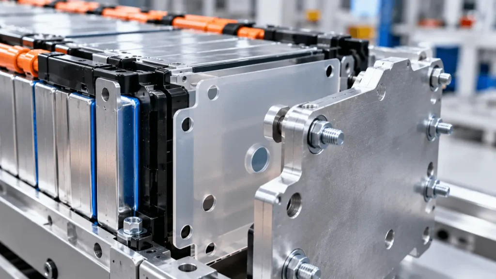
An end plate closes the end of a cell stack and helps the module maintain its intended mechanical geometry. Depending on architecture, it can react assembly preload, support retention features, interface with side rails or tie rods, and help distribute the forces created by cell swelling and vehicle vibration. End plates may also sit near busbars, sensing components, terminal regions, cooling features, and mounting hardware.
That combination makes the location unusual from an insulation perspective. The end plate itself may be metallic and mechanically stiff, while the adjacent cell or nearby conductor can be at a different electrical potential. The insulation layer therefore occupies the same interface where structural loads are transferred. Engineers must prevent unintended conductive contact without designing an insulation part that wrinkles, punctures, shifts, or loses coverage when the module is assembled and loaded.
Why Does the End Plate Need Electrical Insulation?
The purpose of the end-plate dielectric barrier is to maintain electrical separation between potentially energized cell surfaces, terminals or nearby busbar features and conductive structural metal. The exact voltage relationship depends on cell format and module architecture, so the risk assessment must start from the real electrical schematic rather than from a generic assumption that every end plate is grounded.
PC can form a continuous solid-insulation layer across a large face and around selected hardware features. But adding a PC sheet does not eliminate insulation-coordination requirements. Creepage paths along surfaces, clearance through air, exposed metal at a cutout, a washer that overlaps the insulation edge, or a burr that penetrates the part can still create a weak point. The design objective is not simply to place plastic between two parts; it is to preserve the required electrical boundary under manufacturing and service conditions.
Why Is Rigid PC Useful at a Battery End Plate?
Compared with very thin flexible films, a suitable polycarbonate sheet or film can provide a more self-supporting structural dielectric layer. That can be valuable for large end-plate profiles that must retain shape during handling, align to multiple holes or slots, bridge local recesses, and resist incidental contact with stamped metal edges or assembly tooling. PC is also readily converted into repeatable profiles with tabs, windows, radii, and locating features when the selected grade and thickness are compatible with the process.
Rigidity is not automatically an advantage. A stiff part can bridge over uneven surfaces, concentrate load at a boss, or make tolerance conflicts harder to absorb. Material selection should therefore consider electrical requirement, mechanical contact, available gap, part size, service temperature, flame requirement, and the intended assembly method. If the design needs substantial compliance or cushioning, PC usually needs to work with a separate compressible layer rather than being asked to perform as a foam.
Why Does Puncture Resistance Matter?
At an end plate, dielectric failure can begin as a mechanical defect. A stamped edge, washer, fastener head, protruding feature, burr, assembly tool, or localized compression point can create a concentrated load. If that load cuts, thins, creases, or punctures the insulation, the remaining electrical barrier may be much smaller than the drawing intended.
This is where PC can be useful as a tough protective dielectric layer, depending on grade and thickness. The engineering language should remain precise: PC is puncture resistant, not puncture-proof. The relevant question is whether the finished part has sufficient resistance for the actual edge radius, load, support condition, vibration spectrum, and aging state. DFM should therefore review both sides of the interface: the insulation geometry and the metal feature that can damage it. Removing a burr or increasing a corner radius can be as important as increasing insulation thickness.
How Does Cell-Stack Compression Affect PC End-Plate Insulation?
Many module architectures apply preload to the cell stack, and cell swelling can change load over life. The end-plate insulation may therefore experience broad compression plus localized pressure around ribs, bosses, washers, fasteners, or geometric transitions. Its flatness and dimensional stability matter because a local fold or raised edge can become both a mechanical wear point and an electrical coverage problem.
PC should not be treated as the primary compression-management material when the design needs significant deflection, cushioning, or tolerance take-up. Silicone foam, elastomeric pads, or other compliant layers can be assigned that function while PC provides the rigid dielectric surface. In a hybrid stack, engineers should check whether the compliant layer changes contact pressure, lets the PC slide, or drives the PC into a sharp feature. Compression, vibration, and thermal cycling should be evaluated on the actual stack rather than on isolated coupons only.
How Thick Should PC End-Plate Insulation Be?
There is no universal PC thickness for an EV battery end plate. Thickness influences several functions at once: electrical margin, stiffness, puncture resistance, form retention, fit around hardware, available packaging space, mass, and convertibility. The optimum is application- and grade-dependent.
A common mistake is to choose thickness from dielectric strength alone. Electrical performance in the installed part also depends on edge distances, cutouts, conditioning, interfaces, and test method. Mechanical performance depends on the shape and support conditions. A thicker sheet can increase stiffness but may worsen fit or tolerance stack-up; a thinner film may package easily but provide less mechanical protection. Engineers should define minimum required finished thickness, dimensional tolerance, critical local features, and representative electrical/mechanical validation rather than relying on a nominal gauge as a universal design rule.
Why Holes and Fasteners Are Critical in PC End-Plate Insulation
The center of a PC sheet is often not the most vulnerable location. Mounting holes, slots, alignment cutouts, bolt clearances, and edge returns bring conductive hardware close to the dielectric boundary and introduce the largest geometric discontinuities. A fastener can also add localized compression, a washer can bridge an edge, and misregistration can expose metal that was fully covered in CAD.
DFM review should examine hole-to-edge distance, hole-to-conductor distance, washer envelope, slot orientation, narrow webs, internal-corner radii, and the tolerance stack between the PC part and metal structure. The metal drawing matters too: stamped burr direction, edge break, coatings, and insert geometry can change the puncture risk. Where the available insulation land is small, the team should resolve the geometry before tooling instead of assuming the material certificate will compensate for inadequate physical separation.
Creepage and Clearance: Why PC Alone Is Not Enough
Clearance is the shortest distance through air between conductive parts. Creepage is the shortest path along an insulating surface. Both are system-level geometry variables, not intrinsic properties of a PC sheet. Adding a dielectric layer can improve isolation, but it does not automatically correct a short air gap, a conductive fastener path, contamination at a surface, or a cutout that shortens the effective creepage path.
IEC 60664-1 provides a framework for insulation coordination, including clearances, creepage distances, and solid insulation, but the applicable requirements depend on voltage, insulation concept, pollution degree, material, environment, altitude, and the governing product/OEM requirements. For an EV module, engineers should use the applicable vehicle and OEM safety architecture and then translate those requirements into actual edge coverage and spacing on the converted part. Avoid universal millimeter rules detached from the system definition.
PC vs PET vs PI vs Mica at Module End Plates
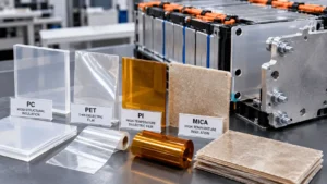
Material choice at an end plate should follow functional zoning rather than a universal ranking. The table below summarizes typical roles; every statement remains grade-, thickness-, geometry-, and test-method-dependent.
| Material | Primary Role | Rigidity | Puncture / Mechanical | Electrical Insulation | High-Temperature Behavior | Best Fit / Main Limitation |
| PC | Rigid structural dielectric barrier | Moderate to high; grade/thickness dependent | Good mechanical skin; puncture-resistant, not puncture-proof | Strong role for suitable electrical/FR grades | Polymeric; flame behavior is grade/thickness specific | Large end-plate profiles, hardware-rich zones; not a severe-heat barrier by default |
| PET | Thin dielectric film | Flexible to semi-rigid | Useful surface protection but typically less structural than PC | Good dielectric role when specified | Polymeric; grade-dependent | Thin, space-efficient isolation where mechanical demand is limited |
| PI | Thin high-temperature dielectric film | Flexible | Thin film; mechanical protection depends on construction | High-value dielectric film applications | Higher-temperature polymer option; grade-dependent | Tight spaces and higher-temperature electrical zones; cost/handling can limit broad panels |
| Mica | High-temperature dielectric / flame-facing barrier | Rigid to semi-rigid; can be brittle | Can need reinforcement or PC carrier around hardware | Strong high-temperature electrical isolation role | Inorganic mica structure offers severe-heat integrity; construction-dependent | Hot-side / flame-facing end-plate zones; conversion and brittleness require care |
PC is typically strongest when the end-plate problem is structural dielectric protection. PET and PI can win where a thinner flexible film is sufficient. Mica becomes more attractive as severe heat or flame exposure dominates. Hybrid stacks can separate these functions, but each additional interface must be validated.
When Should PC and Mica Be Combined?
PC and mica solve overlapping but different problems. PC can provide a rigid, clean dielectric surface with puncture resistance, dimensional control, and accurate locating features. Mica can provide stronger integrity under severe heat or flame-facing exposure and can remain an electrical barrier at temperatures that challenge many polymeric materials. A layered design can therefore assign mechanical protection and assembly geometry to PC while reserving mica for the expected hot side or high-temperature zone.
That does not make PC + mica a default construction. Extra layers add thickness, interfaces, adhesive choices, differential thermal expansion, cost, and validation work. A single-layer PC part may be sufficient where the principal need is electrical and mechanical isolation in the qualified environment. A mica-only part may be more appropriate where severe heat dominates and mechanical support is provided elsewhere. The stack should follow the real risk map rather than a rule that more materials are always safer.
When Should PC Be Combined With Silicone Foam?
A PC + silicone-foam construction is useful when the end interface needs both a rigid dielectric barrier and a compliant mechanical layer. PC can preserve a defined electrical boundary and protect against local abrasion or puncture, while silicone foam can absorb tolerance, reduce vibration transmission, accommodate limited movement, and help manage contact pressure.
The interface must still be engineered. Foam compression changes thickness and force; adhesive can create local hard spots; the PC sheet can slide if retention is inadequate. The design should define which layer carries which function, the intended compression window, whether adhesive is full-face or selective, and how the stack is located during assembly. Validation should use the actual laminate or stacked construction at the intended compression state.
Does Flame Retardancy Mean Thermal Runaway Protection?
No. UL 94 evaluates the flammability behavior of polymeric materials in defined small-scale test configurations. A V-0 classification is useful when a design requires a material that self-extinguishes rapidly under that standardized vertical-burning test, but the classification is grade- and thickness-specific.
A UL 94 result is not a battery thermal-runaway certification, a guarantee against direct flame burn-through, a hot-gas-jet qualification, or proof of pack-level safety. Severe battery events can impose heat flux, duration, particle impact, gas flow, and mechanical conditions that are different from the UL 94 test. If the end-plate zone can see direct flame or hot ejecta, a dedicated high-temperature barrier such as mica, or another validated construction, may be needed. The final stack must be qualified for the actual event definition.
How Does Adhesive Affect PC End-Plate Insulation?
Pressure-sensitive adhesive can simplify placement and retain a large PC part during module assembly, but it becomes part of the electrical and mechanical construction. Its thickness, dielectric behavior, temperature capability, adhesion to the end-plate finish, and aging response are separate from the properties of the PC substrate.
Selective adhesive zones can keep critical edges and vent areas free while providing enough tack for assembly. Full-face adhesive can be appropriate in other designs, but engineers should consider trapped air, squeeze-out, edge exposure, release-liner handling, repositionability, and whether the adhesive changes flatness. Lamination must also maintain registration around holes and cutouts. The design rule is straightforward: raw PC properties do not automatically describe an adhesive-backed finished component.
Common End-Plate Insulation Design Mistakes
The most common errors are system-level, not material-name errors: selecting PC only from dielectric strength; ignoring puncture risk and metal burrs; placing holes too close to conductive features; overlooking washer and fastener envelopes; treating rigid PC as a compression foam; assuming UL 94 V-0 equals thermal-runaway protection; ignoring adhesive limits; and validating only the raw sheet.
Other recurring issues include tolerance stack-up, sharp internal corners, insufficient edge coverage, uncontrolled part orientation, and large-format warpage. These problems are often inexpensive to correct during drawing review and expensive to discover after electrical or module validation. A useful design review asks where the finished part may lose coverage, be punctured, shift, or become electrically bypassed—not merely whether the selected grade has acceptable datasheet properties.
DFM for Custom Die-Cut PC End-Plate Insulation
DFM should begin before prototype tooling because the converter sees risks that may not be obvious in a nominal CAD profile. Review the selected PC grade and thickness, overall part size, flatness requirement, hole diameters and positions, slots, internal corners, edge radii, narrow webs, cut-edge quality, dimensional tolerances, adhesive zones, liner geometry, registration, protective film, part orientation, and packaging method.
Die cutting is efficient for repeatable 2D profiles and production volumes when the geometry and material gauge suit the process. CNC cutting can be appropriate for prototypes, large-format parts, lower volumes, or geometries that are not economical for hard tooling. The manufacturing route should be selected from part size, thickness, edge requirement, volume, tolerance scheme, and change frequency—not from a generic preference for one process. Boost Insulation’s public product pages describe both die-cutting and CNC processing, along with lamination and adhesive integration for custom PC components.
What Changes When PC End-Plate Insulation Becomes Large?
Large-format structural insulation introduces a different tolerance problem from a small terminal cover. Flatness, warpage, thermal expansion, hole registration, cumulative dimensional tolerance, and handling become more important as the part spans a larger area. A small angular or positional error at one locating feature can become a significant mismatch at the opposite end of the sheet.
Packaging and assembly also matter. Large thin parts can bow, scuff, or trap debris during handling. Designers should identify functional datums, critical hole patterns, allowable flatness, orientation features, protective-film requirements, and how the part will be supported during installation. Material utilization matters during nesting, but not at the expense of weak webs or edge coverage. The objective is repeatable installed geometry, not merely sheet yield.
Finished Part ≠ Raw PC Sheet
The raw PC sheet is only the starting material. Cutting can introduce edge or dimensional variation; hole patterns can accumulate registration error; lamination can add curl, bubbles, or contamination; and installation can introduce misalignment or local compression. Each step can change the insulation geometry seen by the module.
For this reason, qualification should move through a hierarchy: raw material → converted part → adhesive-backed or multilayer part → installed end-plate insulation → validated module. Material certificates remain important, but they do not replace inspection and testing of the finished construction. This distinction is especially important when a large part has several holes and interfaces: the broad center area may be electrically robust while one misregistered fastener cutout becomes the limiting feature.
How Should Engineers Validate PC End-Plate Insulation?
Validation should be layered. Raw-material validation confirms the selected grade, thickness, relevant flammability classification, dielectric properties, and supplier-controlled characteristics. Finished-component validation checks dimensions, flatness, edge condition, hole registration, laminate quality, adhesive placement, and other drawing requirements.
Assembly-level validation then introduces the real end plate, fasteners, compression, neighboring conductive structures, and production tolerances. Depending on the project, this can include dielectric withstand and insulation-resistance tests, mechanical puncture or contact checks, compression, vibration, thermal cycling, humidity exposure, adhesion, and post-aging electrical testing. Module-level validation verifies performance in the real electrical and mechanical architecture and according to the OEM or applicable safety plan. No single material or coupon test proves complete EV battery safety.

Industry Insights: What This Means for Engineers and Buyers
Industry Insight 1 — Multifunctional parts are replacing single-property thinking
As energy density increases and packaging space tightens, an end-plate insulator is increasingly expected to combine dielectric isolation, mechanical protection, dimensional control, and assembly support. For engineers and buyers, this means material selection should begin with a function matrix rather than a single dielectric or flame rating.
Industry Insight 2 — End-plate insulation is a mechanical-electrical co-design
Compression, swelling, fastener loads, and structural tolerances can determine whether the dielectric boundary remains intact. Electrical and mechanical teams should review the same interface drawing, because a mechanically acceptable boss or washer can still create an electrical weak point.
Industry Insight 3 — Local hardware can matter more than center-area material performance
The most critical zone is often a hole, edge, burr, or fastener rather than the middle of the sheet. Buyers should therefore request drawing-level DFM and dimensional control instead of comparing only raw-sheet certificates.
Industry Insight 4 — Large-format insulation raises registration and flatness risk
As PC parts become larger, cumulative tolerance, warpage, handling, and hole alignment become more important. Engineering drawings should identify functional datums and critical-to-quality dimensions so inspection focuses on installed performance rather than cosmetic dimensions.
Industry Insight 5 — Converting belongs inside insulation engineering
Die-cut geometry, CNC strategy, adhesive registration, liner design, packaging, and cleanliness can determine whether the specified material reaches the module in the intended condition. Bringing the converter into the design review earlier can reduce rework after prototype validation.
Common Failure Risks in PC End-Plate Insulation
Failure analysis should follow the installed geometry. The table translates common end-plate defects into practical drawing and validation questions.
| Risk | Possible Cause | Potential Effect | Engineering Consideration |
| Puncture | Sharp feature, concentrated load, tool contact | Loss of solid dielectric barrier | Control metal geometry; validate grade/thickness under representative load |
| Edge damage | Poor cutting, scuffing, handling | Reduced edge coverage or crack initiation | Specify edge condition, packaging and handling |
| Hole misalignment | Tolerance stack or registration error | Exposed conductive area / fastener interference | Use functional datums and CTQ hole positions |
| Metal burr contact | Stamped edge or unfinished hole | Local thinning or penetration | Deburr/edge-break metal; review burr direction |
| Fastener compression | Bolt/washer load concentrated on PC | Creep, deformation, puncture or spacing loss | Review washer envelope and load path |
| Insufficient creepage | Short surface path around edge/cutout | Surface leakage/tracking risk | Design to applicable insulation-coordination rules |
| Insufficient clearance | Conductive features too close through air | Air-gap breakdown/arcing risk | Protect required air distances in tolerance stack |
| Warpage | Large format, thermal history, lamination stress | Poor fit, local gaps, misregistration | Define flatness, packaging and conditioning |
| Adhesive squeeze-out | Excess adhesive or pressure | Contamination / changed surface path | Use controlled adhesive zones and lamination process |
| Delamination | Aging, contamination, incompatible adhesive | Part lift, movement, interface voids | Validate adhesive on real substrate and environment |
| Thermal aging | Sustained or cyclic temperature exposure | Property drift or dimensional change | Age the finished construction; re-test electrical/mechanical performance |
| Vibration damage | Relative movement against metal/hardware | Wear, scuffing, shifting | Validate retention and contact surfaces under vibration |
Engineering Checklist for PC End-Plate Insulation
Before locking the material and profile, confirm the following inputs:
- Cell format and module architecture
- End-plate material and surface condition
- System voltage and working voltage
- Required dielectric withstand and insulation resistance
- Selected PC grade and whether flame retardancy is required
- Nominal and minimum finished thickness
- Overall part size and available installation space
- Cell-stack compression and expected cell swelling
- Fastener, washer, bolt and insert locations
- Hole, slot, cutout and narrow-web geometry
- Metal edge condition, burr direction and puncture risk
- Required creepage and clearance
- Operating and peak temperature
- Humidity and contamination environment
- Vibration and mechanical loading
- Adhesive / lamination requirement
- Assembly method, datum strategy and part retention
- Validation plan and post-aging acceptance criteria
What to Send With a PC End-Plate Insulation RFQ
A sourcing package is more useful when it communicates the installation constraints, not only the 2D outline. Include:
- PDF, DXF and/or STEP drawing
- Application location and cell/module architecture
- End-plate material and finish
- System and working voltage
- Dielectric withstand / insulation-resistance requirements
- Preferred FR-PC grade or flame requirement, if already specified
- Nominal/minimum thickness
- Overall dimensions and critical tolerances
- Hole, slot, cutout and fastener locations
- Compression / swelling conditions
- Operating and abnormal temperature requirements
- Creepage / clearance constraints
- Adhesive and lamination requirements
- Prototype quantity and annual volume
- Validation and PPAP requirements
- Packaging, cleanliness and traceability requirements
From PC Sheet to an Assembly-Ready End-Plate Insulator
Boost Insulation’s public website describes support for flame-retardant polycarbonate components through material/DFM review, die cutting, CNC processing, lamination or adhesive integration, prototyping, and production conversion. For an end-plate project, the useful supplier role is not simply shipping a flat PC sheet; it is translating the specified material into a repeatable profile whose edges, holes, adhesive zones, orientation, flatness, and packaging match the battery assembly process.
The engineering discussion should remain tied to the customer’s approved material and validation plan. Grade-specific dielectric, flammability, temperature, puncture, and aging claims should come from the selected material supplier and project test data rather than being generalized across all polycarbonate.
Engineering CTA
If you are designing a PC insulation part for an EV battery module end plate, send Boost Insulation the drawing, selected PC grade or flame requirement, thickness, system voltage, critical hole and fastener locations, creepage/clearance constraints, compression conditions, adhesive requirements, prototype quantity, and annual volume. Reviewing the geometry and material stack before tooling can expose edge, registration, puncture, lamination, and assembly risks before they appear during validation.
FAQ: PC Insulation for EV Battery End Plates
Why do EV battery end plates need electrical insulation?
Because the end plate and its fasteners can be conductive structures close to cell surfaces, terminals, busbars, or other energized features. An insulation layer helps maintain the required electrical separation while the end plate performs its mechanical role. The exact requirement depends on module architecture, voltage relationships, creepage and clearance, and the applicable OEM safety concept.
Why is polycarbonate used for battery end-plate insulation?
Polycarbonate can combine electrical isolation with useful rigidity, dimensional stability, shape retention, and resistance to incidental mechanical damage. Those characteristics suit large profiled barriers around holes, bolts, rails, or metal edges. The appropriate grade and thickness remain application-dependent; PC is not automatically the best material for every end plate.
How thick should PC end-plate insulation be?
There is no universal thickness. Selection depends on dielectric requirements, puncture risk, stiffness, part size, hole and fastener geometry, available space, temperature, flame requirement, and tolerance stack-up. Engineers should validate the selected grade and finished thickness in the actual assembly rather than converting a generic datasheet value into a fixed battery design rule.
Is PC better than PET for battery end plates?
Not universally. PC is often attractive when the barrier needs more rigidity, shape retention, and mechanical protection. PET can be effective when a thin, flexible, economical dielectric film is sufficient and the thermal/mechanical environment is compatible with the selected grade. The end-plate load path and hardware geometry usually determine which profile is more appropriate.
Is PC better than mica for EV battery end plates?
They emphasize different functions. PC is often useful as a structural dielectric layer with puncture resistance and clean geometry. Mica is stronger for severe heat or flame-facing dielectric integrity. Some designs use one material; others combine PC and mica so each layer has a defined role. The correct choice depends on the expected electrical, mechanical, and thermal exposure.
Can PC resist puncture from metal edges or fasteners?
A suitable PC grade and thickness can improve resistance to puncture and mechanical damage, but it is not puncture-proof. Edge radius, burr height, support condition, local pressure, fastener geometry, vibration, aging, and thickness all affect performance. Metal-edge control and DFM are part of the insulation solution.
Does UL 94 V-0 PC protect against thermal runaway?
UL 94 V-0 is a flammability classification under defined test conditions; it is not a thermal-runaway rating. A V-0 PC can be useful as an electrical and structural insulation layer, but direct flame, hot-gas jets, conductive debris, and high heat flux may require a different or additional barrier such as mica or another qualified high-temperature material.
Can adhesive-backed PC insulation be die cut?
Yes, many PC constructions can be laminated with pressure-sensitive adhesive and converted into die-cut parts. The laminate must be engineered as a finished component: adhesive type and thickness, registration, edge exposure, squeeze-out, release liner, flatness, temperature aging, dielectric behavior, and assembly method all require review and validation.
Related Posts:
How to Choose EV Battery Cell Insulation Pads?
What Are EV Battery Module Solutions and How Do They Work?
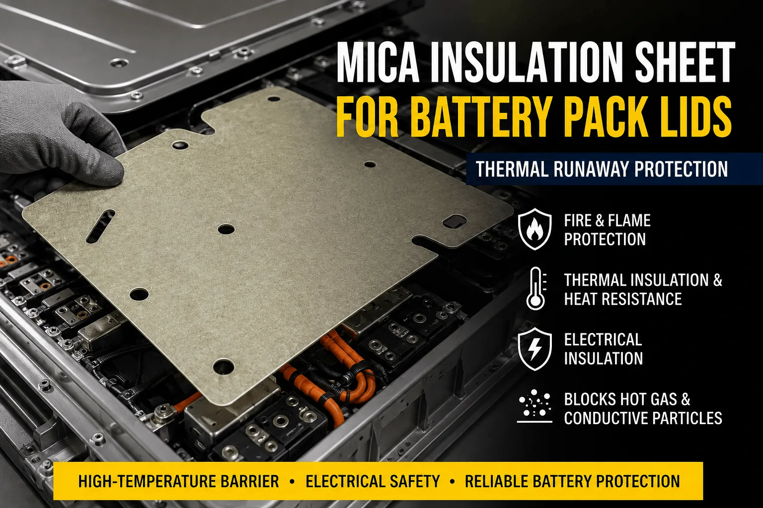
How Does a Mica Insulation Sheet Protect Battery Pack Lids?
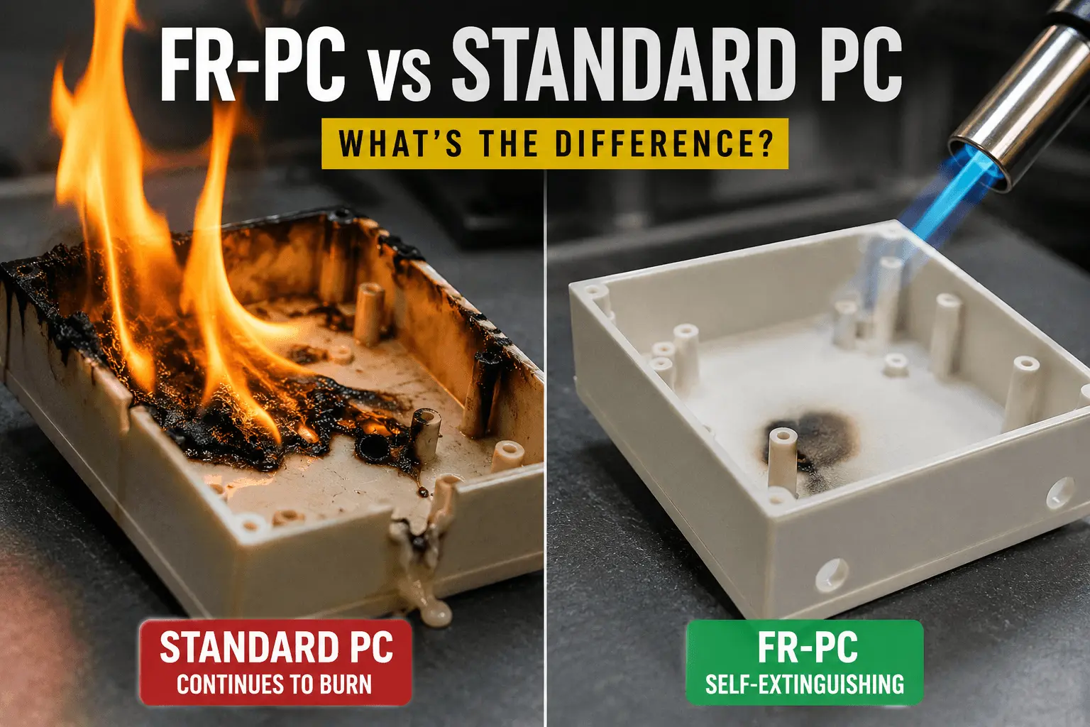
What’s the Difference Between FR-PC and Standard PC?
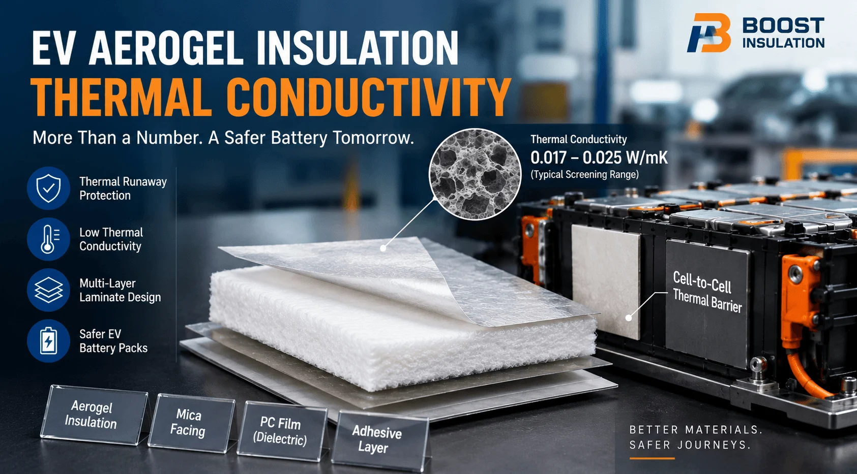
What Density Is Best for Battery Aerogel Insulation?
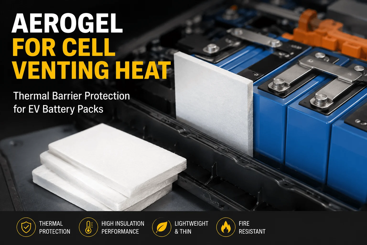
How Does Aerogel Handle Cell Venting Heat in EV Packs?
 betty wong
