
How Does Mica Prevent Dielectric Breakdown in EV Batteries?
Table of Contents
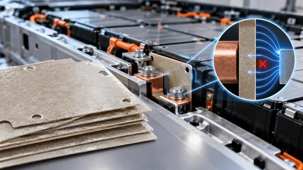
A mica sheet can show strong dielectric performance on a controlled laboratory coupon—but will the finished die-cut part still prevent electrical failure after holes are added, a fastener compresses the edge, adhesive is laminated to one face, humidity enters the pack, and years of vibration and thermal cycling accumulate? In an EV battery, dielectric breakdown is not determined by one attractive kV/mm number. It is the result of voltage, electric-field distribution, geometry, interfaces, contamination, aging, and the weakest local feature in the installed insulation system.
Mica helps reduce dielectric breakdown risk in EV batteries by forming a high-dielectric barrier between energized conductors and nearby conductive structures. For mica dielectric breakdown in EV batteries, however, reliable performance depends on more than raw-sheet dielectric strength. Thickness, electric-field concentration, cut edges, holes, cracks, voids, adhesive interfaces, moisture, contamination, thermal aging, creepage, clearance, and metal hardware can all create local weak points. Engineers should therefore design the complete insulation geometry and validate the finished die-cut mica component under representative electrical, thermal, mechanical, and environmental conditions.
Key Takeaways
- Dielectric strength is a material test result; dielectric reliability is a property of the complete insulation system.
- Breakdown voltage and dielectric strength are related but are not interchangeable design guarantees, especially when thickness, electrode geometry, conditioning, and test method change.
- The weakest electrical location may be a cut edge, hole, burr, fastener, void, delaminated interface, contaminated surface, or compressed region rather than the center of the mica sheet.
- Mica does not remove the need for insulation coordination, including suitable creepage and clearance for the actual voltage, pollution environment, material system, and applicable standard.
- Qualification should move from raw material to finished component, installed assembly, and module/pack validation, with electrical testing repeated after relevant aging and environmental exposure.
What Is Dielectric Breakdown in an EV Battery?
Electrical insulation is intended to restrict current flow between conductors at different potentials and between energized parts and grounded or conductive structures. Dielectric breakdown occurs when the electrical stress at a location exceeds what the insulation system can withstand under the relevant conditions. A conductive path can then form through the insulation, along an interface, or across a surface. Depending on the circuit and protection architecture, the result can include excessive leakage, arcing, a short circuit, damage to adjacent components, or loss of required high-voltage isolation.
For EV engineers, the important word is system. A battery pack contains cells, busbars, terminals, contactors, fuses, current collectors, sensing circuits, cooling structures, module frames, fasteners, and an enclosure within a tightly packaged volume. The electric field is shaped by those conductors and by the geometry and dielectric properties of the materials between them. The center area of a flat mica coupon may never experience the same field distribution as the edge of a terminal window or the region beneath a washer.
This is why a breakdown investigation should ask where the electrical stress is concentrated, what path current can take, and how that path changes after manufacturing, installation, humidity, vibration, heat, or contamination—not simply whether the raw sheet passed a laboratory test.
Why Is Mica Effective Against Dielectric Breakdown?
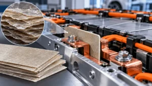
Mica is widely used as an electrical-insulation material because its layered inorganic mineral structure can provide strong dielectric behavior while remaining physically stable at temperatures that challenge many polymer films. In an EV battery, a properly selected mica sheet or laminate can separate busbars from metal frames, isolate terminals and junction areas, cover conductive enclosure features, or preserve an insulating barrier when nearby materials are heated.
That combination is valuable because electrical failure modes do not occur only at room temperature. A polymer film that performs well during normal service may shrink, soften, carbonize, or lose mechanical support under an abnormal heat event. A mica-based barrier can help preserve separation, but the finished construction may include binder, glass reinforcement, film, pressure-sensitive adhesive, printed layers, and other interfaces. Those layers can change the electrical and mechanical result.
The practical engineering conclusion is narrower than the phrase ‘mica has high dielectric strength.’ Mica provides a useful dielectric foundation, but the reliability of the installed part depends on grade, minimum thickness, surface condition, converted geometry, attachment, aging, and the surrounding conductive structure.
Dielectric Strength vs Breakdown Voltage: What Is the Difference?
Breakdown voltage is the voltage at which a particular specimen electrically fails under a defined test configuration. Dielectric strength is a breakdown-related electric-field value, commonly expressed relative to specimen thickness. The concepts are related, but they are not identical and should not be treated as interchangeable drawing requirements.
ASTM D149 and IEC 60243-1 are examples of standardized methods used to evaluate the electric strength or breakdown behavior of solid insulating materials under specified conditions. ASTM D149 explicitly treats the test as condition-dependent: specimen thickness, electrodes, surrounding medium, voltage application, conditioning, and failure criteria can influence the result. IEC 60243-1 likewise defines short-time electric-strength testing at power frequency and includes surface breakdown methods. These standards are useful for consistent material characterization; they are not a shortcut to a pack-level voltage rating.
A common sourcing error is to take a datasheet number in kV/mm and multiply it by any chosen thickness to predict guaranteed withstand voltage. That linear assumption can fail because breakdown behavior can be thickness-dependent, field distribution changes with geometry, and production components contain edges, holes, interfaces, tolerances, and environmental exposure that a simple material coupon does not represent. Use supplier data for screening, then define component-level test voltage and acceptance criteria for the actual construction.
Why Datasheet kV/mm Does Not Equal Pack-Level Withstand Voltage
A dielectric datasheet value usually comes from a controlled specimen. Its surfaces are prepared, the thickness is known, the electrodes have defined shapes, the environment and conditioning are controlled, and the voltage is applied according to a stated method. The result is valuable because it allows materials or grades to be compared under repeatable conditions.
The installed EV component is different. Die cutting creates perimeter edges, holes, slots, narrow webs, registration tolerances, and local thickness variation. Lamination introduces adhesive interfaces and possible air pockets. Installation adds fasteners, compression, stamped metal, busbar corners, assembly tolerances, and contamination risk. Vehicle life adds humidity, thermal cycling, vibration, and aging. An abnormal event can add carbonized organic residue or mechanically displace the part.
The evidence hierarchy should therefore be: raw material coupon, production-intent die-cut component, installed assembly, then representative module or pack. Each level answers a different question. A high raw-sheet value can support material selection, but it cannot prove that a busbar insulator with a tight terminal cutout will maintain isolation after assembly and aging.
RAW MATERIAL COUPON → DIE-CUT PART → INSTALLED COMPONENT → MODULE → PACK
How Does Mica Thickness Affect Dielectric Breakdown?
Increasing thickness can increase the amount of solid insulation between conductors and may improve voltage withstand in a given construction, but thickness is not a simple linear guarantee. The relationship between thickness and measured electric strength can vary by material, construction, electrode configuration, defects, and test method. A thicker part also changes stiffness, bending behavior, package space, thermal response, mass, and die-cut manufacturability.
For a die-cut mica insulator, minimum finished thickness matters more than nominal sheet thickness alone. Local compression under hardware, thickness variation in laminated regions, binder distribution, edge chipping, or handling damage can create a thinner or weaker zone. If qualification uses a thick, ideal coupon but production allows a lower minimum thickness around a critical conductor, the validation margin may not represent the real part.
Thickness selection should start with system and working voltage, required dielectric withstand, insulation coordination, mechanical protection, thermal needs, space, and manufacturing capability. Then validate the minimum production-intent construction. Avoid design rules such as ‘double the mica thickness and the breakdown voltage doubles.’
Why Electric-Field Concentration Matters
Electric field is not necessarily uniform across a battery assembly. Sharp conductive features, small radii, corners, terminal edges, busbar steps, fastener heads, washers, and narrow air gaps can concentrate the field locally. A part can therefore experience its highest dielectric stress at a geometrical feature even when the average voltage divided by distance appears acceptable.
This is one reason insulation coordination is more than selecting a material. IEC 60664-1 addresses principles for clearances, creepage distances, and solid insulation within its scope, illustrating the broader concept: geometry, environment, overvoltage conditions, and the insulation system must be coordinated. The exact EV requirement depends on the vehicle architecture, working voltage, transient conditions, pollution environment, applicable standards, and OEM design rules.
At the component level, review conductor radii, hole locations, edge distances, local gaps, and metal transitions. Finite-element electric-field analysis may be appropriate for critical high-field areas, but a generic simulation should not be substituted for geometry-specific engineering. The manufacturing drawing must preserve the geometry that was validated.
Why Cut Edges, Holes, and Slots Can Become Weak Points
The center of a mica sheet may not be the electrically weakest location in the finished part. Layered mica constructions can chip, crack, or delaminate at cut edges. A hole can reduce the available edge distance to a conductor. A slot can create a narrow web that is vulnerable to handling damage. A sharp internal corner can become a crack initiator. Registration error can shift a protective window until metal becomes exposed.
These issues matter around busbars, terminals, service disconnects, contactors, fuse zones, and enclosure fasteners because the insulation often needs complex cutouts exactly where electric-field stress is already high. If a screw passes through the mica, the design must consider the actual conductive path around the screw head, washer, hole edge, and adjacent metal—not only the bulk mica between flat surfaces.
DFM should therefore review minimum web width, internal radii, hole-to-edge distance, hole-to-conductor distance, feature registration, unsupported spans, cutting direction where relevant, and how the part is stripped from the tool or carrier. Precision converting cannot increase the intrinsic dielectric strength of mica, but it can preserve the intended insulation geometry and reduce conversion-induced weak points.
Can Cracks, Voids, and Delamination Cause Dielectric Failure?
Yes. Cracks and delamination can create discontinuities, air gaps, altered interfaces, and local changes in electric-field distribution. They can also provide pathways for moisture or contamination. A void in an adhesive-backed laminate is not automatically a failure, but it changes the local dielectric structure and should be evaluated in the context of voltage, geometry, void size, waveform, pressure, temperature, and the surrounding materials.
Partial discharge is relevant to some high-field insulation systems, especially when voids or interfaces experience sufficient local stress, but it should not be assumed to be a universal requirement for every EV mica part. IEC 60270 defines charge-based partial-discharge measurement methods; whether such testing is appropriate depends on the specific system and acceptance criteria.
From a manufacturing perspective, the practical controls are consistent lamination pressure, cleanliness, flatness, edge inspection, crack limits, adhesive coverage, and dimensional inspection. If a critical part is multilayer, qualify the laminate as a laminate. Separate certificates for the mica and adhesive do not demonstrate the electrical behavior of the bonded interface.
How Do Temperature and Thermal Aging Affect Mica Insulation?
The mica mineral can remain stable under heat that degrades many organic materials, but electrical reliability after aging depends on the complete construction. Binder and adhesive can harden, soften, shrink, char, or lose adhesion. Differential thermal expansion can create curling or delamination. Repeated thermal cycling can grow microcracks around holes or stressed bends. Mechanical support can change as organic layers age.
After severe heat, visual survival does not prove dielectric survival. Carbonized adhesive or residue may be more conductive than the original layer. A part can remain physically present but develop cracks, edge exposure, contamination, or loss of creepage path. Conversely, some constructions may retain sufficient electrical separation despite visible cosmetic change. The correct pass criterion depends on the required post-event function.
For this reason, repeat relevant dielectric-withstand and insulation-resistance measurements after thermal aging, thermal cycling, or abuse exposure when the application requires retained isolation. The detailed heat-survival mechanism belongs in a dedicated high-temperature mica article; the key breakdown lesson is that post-aging electrical performance must be measured rather than inferred from mineral heat resistance.
How Do Humidity and Contamination Affect Electrical Insulation?
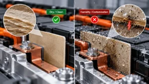
Bulk dielectric strength is only one part of high-voltage insulation reliability. Surface condition matters because moisture, dust, metal particles, ionic residue, coolant contamination where relevant, adhesive strings, fingerprints, and process debris can change leakage paths along an insulating surface. These effects are especially important near edges, holes, and hardware where the real creepage path may already be constrained.
Surface tracking is distinct from bulk puncture through the mica. Tracking involves progressive conductive path formation along a surface under electrical stress and contamination conditions. IEC 60112 provides standardized methods for comparative and proof tracking indices of solid insulating materials, but the standard itself does not turn a material CTI result into a universal safe creepage distance. Application geometry and applicable insulation-coordination rules still control the design.
For engineers and buyers, this translates into cleanliness requirements, controlled packaging, surface-inspection criteria, humidity conditioning where appropriate, and electrical testing after environmental exposure. A mica part with strong bulk dielectric performance can still fail if conductive contamination bridges the effective surface path.
Why Creepage and Clearance Still Matter
Clearance is the shortest distance through air between conductive parts. Creepage is the shortest path along the surface of an insulating material between conductive parts. Adding a mica sheet can change both paths, but mica does not eliminate the need to design them correctly.
A sheet placed beneath a busbar may provide excellent through-thickness insulation yet leave an exposed edge where the surface path to a grounded bracket is too short. A mounting hole can allow a washer to reduce the effective path. Adhesive squeeze-out or contamination can create a different surface condition than the one assumed in CAD. A slot intended to add distance may lose its benefit if the converted part shifts during assembly.
Do not copy a single universal millimeter value into every project. Required distances depend on voltage, overvoltage conditions, insulation concept, pollution degree, material characteristics, environment, altitude where relevant, system architecture, and the applicable standard or OEM requirement. Treat creepage and clearance as geometry requirements that must survive tolerance stack-up and vehicle life.
Can Adhesive Become the Weakest Electrical Layer?
Yes. An adhesive-backed mica component is a multilayer insulation system, not simply ‘mica with sticky backing.’ The adhesive has its own dielectric properties, thickness variation, moisture response, temperature aging behavior, contamination sensitivity, and bond characteristics. It can also create air pockets, squeeze-out, exposed edges, or delamination if the pattern and assembly process are poorly controlled.
Full-surface pressure-sensitive adhesive may simplify installation, while selective adhesive zones can keep polymer away from high-field edges or reduce squeeze-out risk. The right approach depends on substrate surface energy, assembly sequence, required positional stability, service temperature, humidity, and whether the adhesive itself is part of the dielectric path. The release liner and kiss-cut design also affect placement accuracy.
Do not assign the raw mica’s dielectric rating to the adhesive-backed part. Validate the actual production laminate, including minimum adhesive thickness where electrically relevant, edge condition, environmental aging, peel or shear requirements, and the electrical test configuration used for the installed part.
Engineering rule: raw mica dielectric performance ≠ adhesive-backed mica component performance.
Why Metal Burrs and Fasteners Matter
Stamped metal edges, busbar burrs, screw heads, washers, and fasteners can defeat otherwise adequate insulation. A sharp burr can reduce local spacing, concentrate the electric field, abrade the mica, or puncture a thin laminate under assembly load. A fastener can compress a stack until the local mica thickness changes or the edge cracks. A washer can create an unexpected conductive overhang near a cutout.
The insulation drawing should therefore be reviewed together with the mating metal drawing. Critical inputs include burr direction and limit, edge radius, hardware envelope, torque or clamp load where relevant, tolerance stack-up, possible movement under vibration, and whether the part is installed before or after the fastener operation.
For high-risk zones, consider protective geometry rather than simply adding a thicker sheet everywhere. Larger radii, local overlap, reinforced laminates, protective polymer facings, improved metal finishing, or hardware relocation can be more effective. The engineering question is how to remove the local weak point while maintaining manufacturability and assembly access.
What Happens After Thermal Runaway or Severe Heat Exposure?
From a dielectric perspective, a severe battery event creates a new insulation condition. The engineer should ask whether the mica remains in position, whether the binder or adhesive has degraded, whether cracks or delamination formed, whether conductive carbonized residue is present, and whether hot gas or ejecta deposited conductive contamination on the surface. Mechanical displacement can also shorten clearance or expose a metal edge.
Mica can be valuable because the inorganic barrier may remain physically present after many polymeric layers have lost integrity. But ‘the mica survived’ is not the same as ‘the required electrical isolation survived.’ If post-event isolation is part of the safety concept, test it directly after representative exposure. The acceptance criteria may include insulation resistance, dielectric withstand, absence of direct metal-to-metal contact, retained geometry, or other system-specific requirements.
This distinction also prevents misuse of flammability or heat-resistance data. A fire test, thermal-runaway test, or maximum-temperature statement does not automatically establish retained dielectric performance. Thermal and electrical validation must be connected at the finished-component and assembly level.
Common Causes of Dielectric Failure in Mica Insulation Parts
Most failures are not explained by one variable. They usually combine a local geometry issue with material variation, environment, or aging. The most common engineering risks include insufficient minimum thickness; incorrect grade or construction; sharp conductive geometry; poor cut-edge quality; cracks; narrow webs; hole or fastener interference; adhesive contamination or squeeze-out; moisture; conductive debris; delamination; thermal aging; installation misalignment; metal burrs; and inadequate creepage or clearance.
Another recurring failure mode is validation mismatch. The engineering team approves a raw mica coupon, procurement changes to an adhesive-backed version, the converter adds a carrier or liner, and the final part is tested only dimensionally. The electrical system has changed, but the qualification evidence has not. Change control should cover mica grade, binder, reinforcement, film, adhesive, thickness, conversion process, and other layers that can affect the approved insulation behavior.
A useful failure-prevention review asks: Where is the highest electric stress? What is the weakest physical feature? What changes after aging? What can move, crack, contaminate, or compress? And which test actually demonstrates the required function at the production-part level?
How Precision Die Cutting Helps Reduce Insulation Risk
Precision die cutting does not increase mica’s intrinsic dielectric strength. Its value is that it converts the material into a repeatable geometry that preserves the intended electrical separation. Critical outputs include edge condition, hole position, minimum web width, internal radius, registration between layers, adhesive placement, cleanliness, and dimensional consistency.
Early DFM is especially important for mica because layered constructions can behave differently from homogeneous polymer film. Tight internal corners can crack. Very narrow webs can break during stripping or handling. A hole pattern that is easy to draw may leave insufficient material around a fastener. A laminate may require different tool support than a single sheet. Release-liner design can affect how accurately a large fragile part is placed in the pack.
Boost Insulation’s public website describes DFM support, precision die cutting, lamination, rapid prototyping, and production of custom insulation components. For a breakdown-sensitive part, the commercial value is not merely supplying mica sheet; it is converting an approved insulation stack into a repeatable, assembly-ready component while controlling geometry and interfaces that can become electrical weak points.
How Should Engineers Validate a Finished Mica Insulation Part?
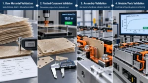
Validation should be layered because no single test proves battery-pack safety or long-term dielectric reliability. At the raw-material level, confirm grade identity, thickness, relevant dielectric data, insulation resistance where specified, surface condition, and environmental conditioning using appropriate standards or supplier methods. Material data is the baseline, not the finish line.
At the finished-component level, test the production-intent laminate and geometry. Verify dimensions, minimum thickness, edges, holes, cracks, delamination, adhesive placement, flatness, cleanliness, and the defined dielectric-withstand or insulation-resistance requirement. If the component will be aged, repeat electrical testing after thermal aging, humidity, thermal cycling, vibration, or other relevant conditions.
At the assembly level, install the part with real busbars, hardware, substrates, compression, and tolerance stack-up. Check that creepage and clearance remain as designed and that fasteners or burrs do not damage the insulation. At module or pack level, validate the electrical safety functions required by the vehicle architecture and applicable standards. ISO 6469-3 is one relevant vehicle-level electrical-safety reference for voltage-class-B electric circuits, but OEM requirements and system-specific validation still govern the actual program.
The strongest evidence chain therefore follows the product: raw material → converted part → installed assembly → module/pack. If a design change alters the insulation geometry or stack, review whether revalidation is needed.
Important Technical Distinctions
| Concept A | Concept B | Why the distinction matters |
| Dielectric strength | Breakdown voltage | Field-related material test result vs voltage at failure of a defined specimen. |
| Insulation resistance | Dielectric strength | Resistance to leakage current vs resistance to breakdown under high electric stress. |
| Bulk breakdown | Surface tracking | Failure through material thickness vs progressive conductive path along a surface. |
| Creepage | Clearance | Shortest path along an insulating surface vs shortest distance through air. |
| Raw-material test | Finished-component test | Controlled material coupon vs converted geometry with edges, holes, layers, and process variation. |
| Working voltage | Dielectric-withstand test | Normal electrical stress vs defined validation/proof stress; one does not substitute for the other. |
| Heat resistance | Electrical retention after heat | Survival under temperature vs retained dielectric function after exposure. |
Common Dielectric Breakdown Risks in Mica EV Battery Insulation
| Risk Factor | How It Affects Insulation | Typical Location | Engineering Consideration |
| Insufficient minimum thickness | Reduces solid-insulation margin; local compressed zones may control | Flat barrier, clamp zone | Specify minimum finished thickness and validate production-intent parts. |
| Cut-edge crack | Creates discontinuity and may shorten surface path | Terminal windows, perimeter edges | Use suitable radii, tooling, support, and measurable edge criteria. |
| Metal burr | Concentrates field; may abrade or puncture insulation | Stamped busbars, brackets | Control metal finishing and review burr direction/edge radius. |
| Fastener / washer | Reduces spacing and can compress or crack mica | Mounting holes, end plates | Review hardware envelope, load, hole clearance, and tolerance stack. |
| Narrow web | Fragile geometry can crack or shift | Between slots or adjacent holes | Set DFM minimum web based on exact grade and process. |
| Adhesive squeeze-out | Changes surface condition or creepage path | PSA-backed edges and holes | Control adhesive pattern, thickness, and edge setback. |
| Void / air pocket | Changes local dielectric structure and field distribution | Laminated regions | Control lamination; assess need for void/PD evaluation case by case. |
| Delamination | Creates interfaces, gaps, movement, and moisture paths | Edges, bends, aged laminates | Validate adhesion and electrical performance after conditioning. |
| Humidity | Can lower surface insulation resistance | Exposed surfaces and edges | Condition and test finished parts for relevant humidity exposure. |
| Contamination | Can create leakage or tracking paths | Busbar zones, assembly surfaces | Define cleanliness, packaging, and process controls. |
| Thermal aging | Can degrade binder/adhesive and create cracks or residue | High-temperature zones | Repeat electrical tests after representative aging. |
| Misalignment | Exposes conductor or reduces intended edge distance | Large die-cut parts, automated placement | Use registration features and assembly poka-yoke where practical. |

Industry Insights: What This Means for Engineers and Buyers
Industry Insight 1 — Higher voltage raises the value of insulation coordination
As EV architectures move to higher working voltages, the response should not be ‘buy the material with the highest dielectric-strength number.’ Higher voltage increases the importance of field distribution, clearances, creepage, transients, interfaces, and manufacturing consistency. Engineers should spend more time locating local stress concentrations; buyers should request evidence tied to the finished construction and defined test conditions.
Industry Insight 2 — Compact packaging makes tolerance stack-up an electrical issue
When the available insulation envelope shrinks, small shifts in hole position, edge distance, fastener location, or laminate registration consume a larger share of the design margin. DFM and dimensional capability become part of electrical insulation engineering. Procurement should treat critical geometry and inspection criteria as functional requirements, not cosmetic drawing details.
Industry Insight 3 — Finished-component validation is replacing datasheet-only qualification
Raw-material certificates remain important, but they are increasingly insufficient for parts containing adhesive, reinforcement, complex cutouts, or severe environmental exposure. Engineering teams gain more useful evidence by testing production-intent parts before and after aging. Buyers should ask what exact construction was tested, not only which mica family appears on the certificate.
Industry Insight 4 — Interfaces can become the limiting layer
Adhesive-backed and multilayer insulation parts create interfaces that may contain voids, thickness variation, moisture pathways, or different dielectric properties. This does not make multilayer designs undesirable; it means the interface must be designed and validated. The finished stack, not the mica layer in isolation, should be the controlled engineering item.
Industry Insight 5 — Converting suppliers are moving upstream into insulation DFM
Edge quality, hole location, minimum webs, layer registration, adhesive zoning, and cleanliness can determine whether the installed geometry matches the electrical design. Engineers benefit from involving the converter before geometry freeze; buyers benefit because early DFM can reduce prototype failures, tooling changes, and late PPAP revisions.
Engineering Checklist for Mica Dielectric Insulation
- System voltage and working voltage
- Transient or overvoltage conditions
- Required dielectric withstand and test method
- Insulation resistance requirement
- Mica grade and complete laminate construction
- Nominal and minimum finished thickness
- Part geometry and protected conductive zones
- Creepage requirement and actual surface path
- Clearance requirement and tolerance stack-up
- Hole and slot locations
- Fastener and washer locations
- Metal edge condition, burr direction, and edge radius
- Available installation space
- Operating, peak, and abnormal temperature conditions
- Thermal-aging and thermal-cycling exposure
- Humidity and contamination environment
- Compression, clamp load, and vibration
- Adhesive type, coverage, thickness, and liner design
- Required post-aging or post-event dielectric performance
- Component-, assembly-, and system-level validation method
What to Send With a Custom Mica Insulation RFQ
- PDF plus DXF and/or STEP drawing
- Application location and neighboring high-voltage / grounded structures
- System voltage and working voltage
- Dielectric-withstand requirement, waveform, dwell, and acceptance criteria
- Insulation-resistance requirement
- Specified mica grade or approved material family, if already selected
- Nominal and minimum finished thickness
- Dimensional tolerances and critical-to-function dimensions
- Hole, slot, cutout, and minimum-web geometry
- Metal interface information, including burr or sharp-edge concerns
- Creepage and clearance constraints
- Operating, peak, and abnormal temperature conditions
- Humidity, contamination, coolant, or other environmental requirements
- Adhesive and adhesive-pattern requirement
- Lamination, reinforcement, film, or multilayer-stack requirement
- Prototype quantity and validation schedule
- Annual volume and production ramp assumptions
- Validation, PPAP, traceability, and change-control requirements
- Packaging, cleanliness, liner, orientation, and handling requirements
Engineering CTA
If you are developing a mica insulation component for a high-voltage battery assembly, send Boost Insulation the PDF/DXF/STEP drawing, system and working voltage, dielectric-withstand and insulation-resistance requirements, mica thickness, creepage and clearance constraints, hole and fastener locations, metal-edge conditions, adhesive or laminate requirements, environmental validation plan, prototype quantity, and annual volume. Reviewing those details before tooling allows the material stack, critical geometry, conversion risks, and assembly weak points to be addressed before prototype electrical validation or production release.
Frequently Asked Questions
What causes dielectric breakdown in EV battery insulation?
Dielectric breakdown occurs when local electrical stress exceeds the capability of the insulation system under the actual conditions. Causes can include insufficient thickness, sharp conductive geometry, inadequate spacing, cracks, voids, cut-edge damage, contamination, moisture, adhesive interfaces, thermal aging, compression damage, or misalignment. The failure path can be through the bulk insulation, across an interface, or along a contaminated surface, so diagnosis should focus on the complete installed geometry rather than one material value.
How does mica help prevent dielectric breakdown?
Mica helps by creating a solid dielectric barrier between conductors at different potentials and between energized parts and conductive structures. Its electrical-insulation behavior and high-temperature physical stability make it useful around busbars, terminals, frames, and junction areas. It reduces risk rather than guaranteeing prevention. Thickness, geometry, edges, holes, adhesives, environment, aging, creepage, clearance, and hardware must still be designed and validated.
Is dielectric strength the same as breakdown voltage?
No. Breakdown voltage is the voltage at which a defined specimen fails in a particular test. Dielectric strength is a breakdown-related electric-field value, often normalized by thickness. Test method, specimen thickness, electrode geometry, conditioning, temperature, humidity, and failure criteria can affect results. A datasheet kV/mm value should therefore not be treated as a direct guaranteed withstand voltage for a finished EV battery part.
Does thicker mica always provide higher breakdown voltage?
Not as a simple linear rule. More thickness can increase solid insulation distance, but measured breakdown behavior depends on construction, defects, electrode geometry, field distribution, and test method. A thicker sheet can also be stiffer, harder to form, or more vulnerable around tight cutouts. Engineers should select thickness from system requirements and validate the minimum production-intent finished part rather than assuming that doubling thickness doubles breakdown voltage.
Can holes and cut edges reduce mica insulation performance?
Yes. Holes and cut edges can reduce available distance to conductors, create narrow webs, expose adhesive, initiate cracks, or interact with screws, washers, and burrs. Layered mica can also chip or delaminate if the geometry or cutting process is unsuitable. The important design variables include edge distance, internal radius, hole position, fastener envelope, registration, and cut quality—not only the sheet center.
Can adhesive affect mica dielectric insulation?
Yes. Adhesive adds another dielectric layer and interface with its own thickness, moisture response, temperature aging, contamination risk, and potential for air pockets or squeeze-out. The mica layer can have excellent dielectric performance while the adhesive-backed component behaves differently. Qualify the actual production laminate, including adhesive pattern, substrate, edge condition, aging, and the same electrical test configuration used for the application.
How do humidity and thermal aging affect mica insulation?
The mica mineral may remain stable, but humidity and aging can change surface leakage, binder condition, adhesive performance, dimensional stability, cracks, and contamination. Carbonized or degraded organic layers can also change post-heat electrical behavior. For critical applications, repeat insulation-resistance and dielectric testing after representative humidity, thermal cycling, heat aging, vibration, or severe-heat exposure instead of testing only new dry material.
Should engineers test the raw mica sheet or the finished die-cut part?
Both, for different purposes. Raw-sheet testing verifies material identity and baseline properties. Finished-part testing captures thickness, edges, holes, adhesive, lamination, contamination, and manufacturing variation. Assembly testing adds real metal geometry, fasteners, compression, and tolerance stack-up. Module or pack testing confirms the system-level electrical safety function. A robust qualification plan moves through all four levels rather than treating a material certificate as final validation.
Related Posts:
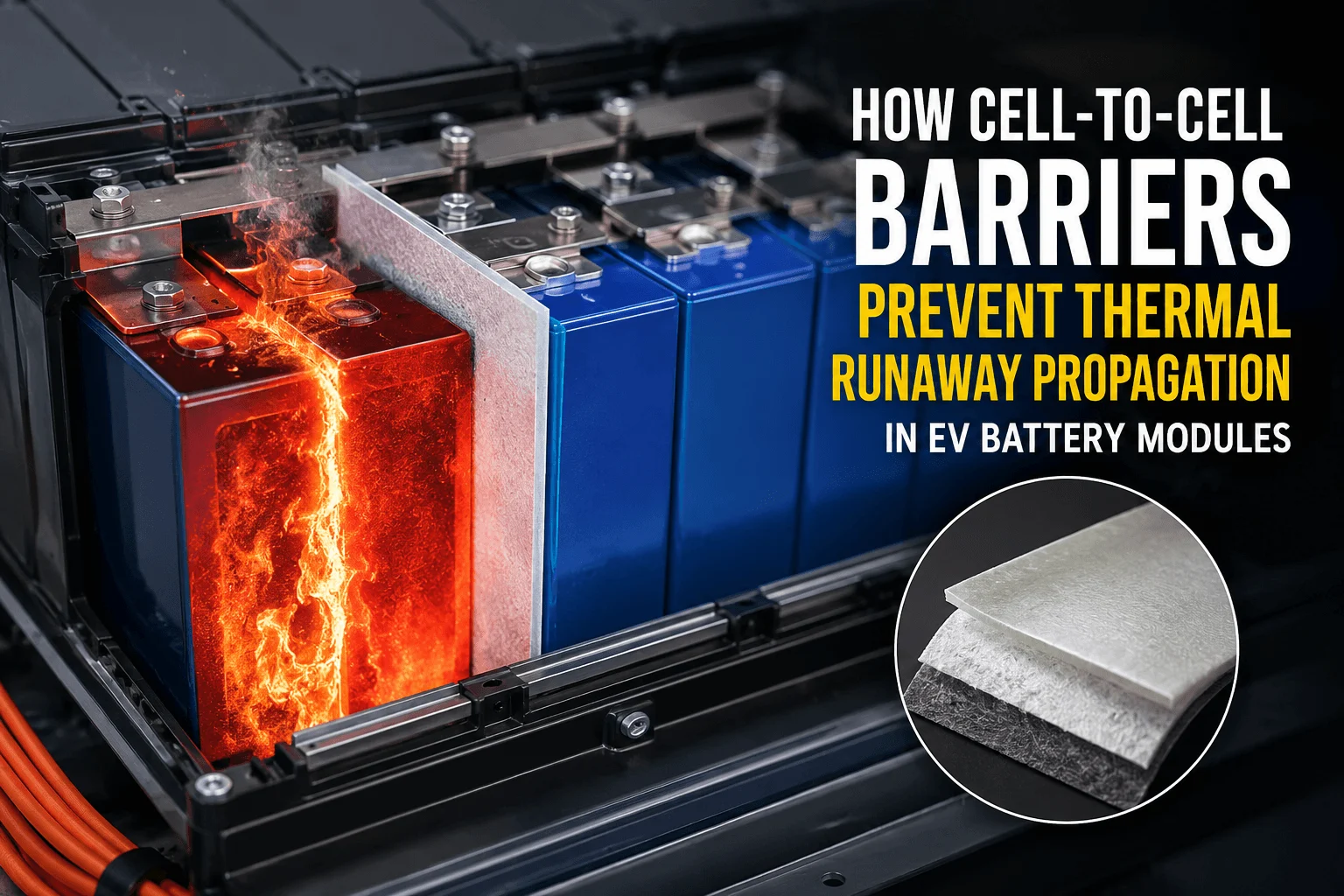
How Do Cell-to-Cell Barriers Prevent Thermal Runaway?
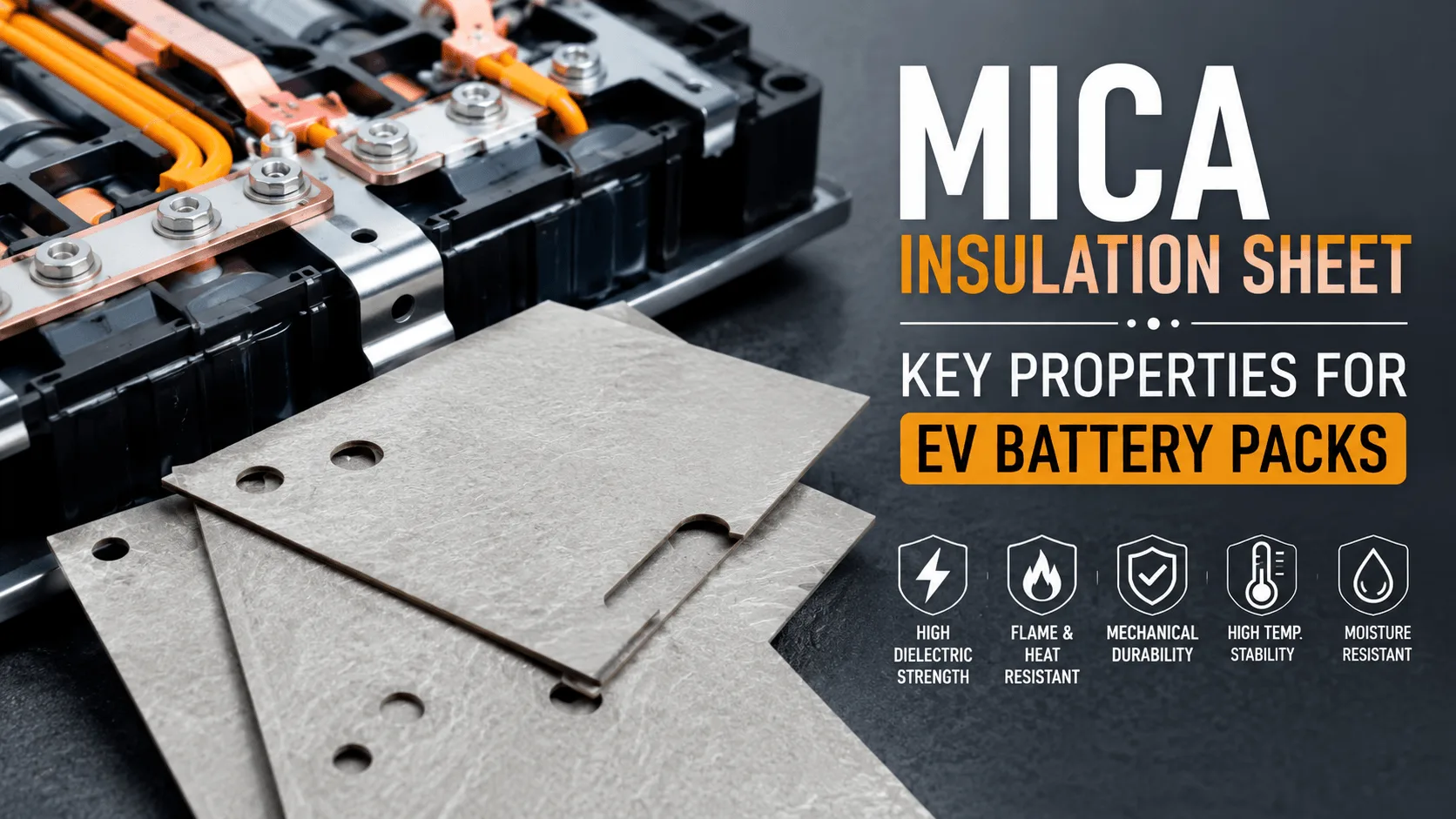
What Properties Make a Mica Insulation Sheet Effective?
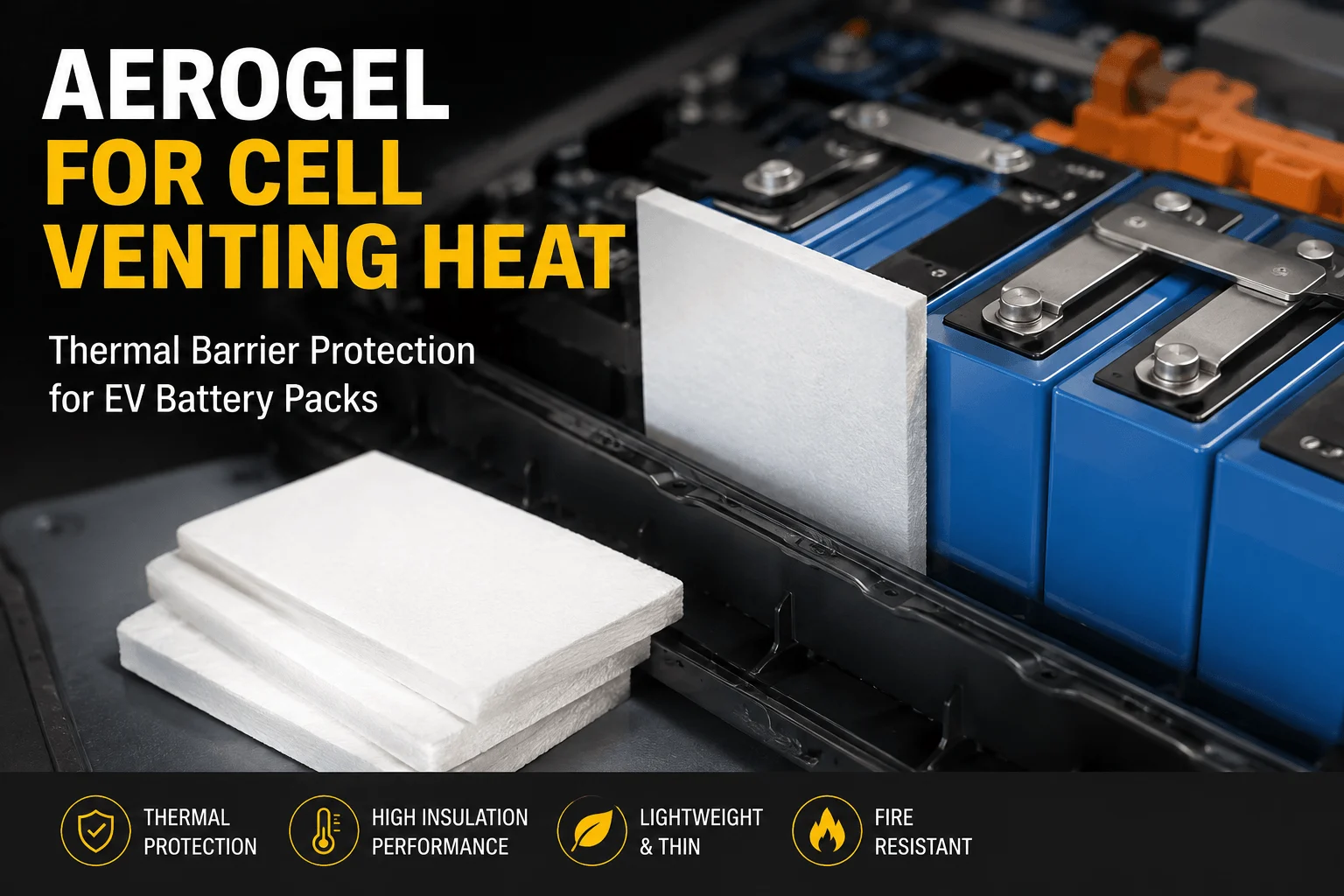
How Does Aerogel Handle Cell Venting Heat in EV Packs?
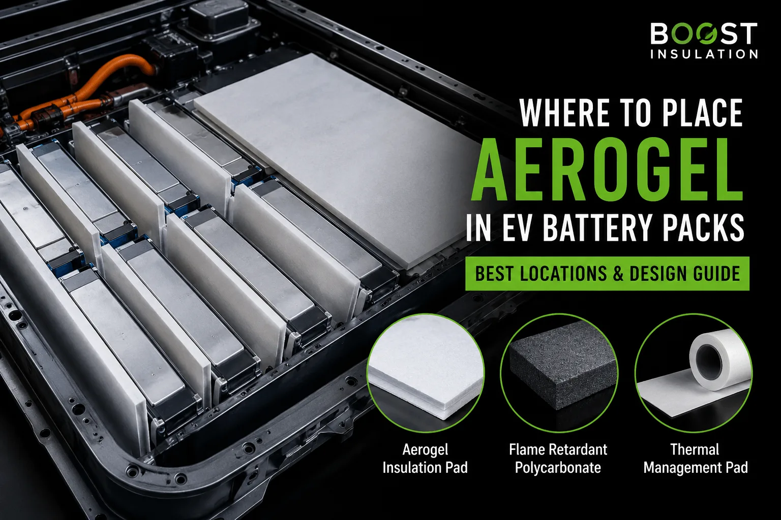
Where Is Aerogel Used Inside Modern EV Battery Packs?
FR4 vs PC for EV Battery Mounting Plates: How to Choose?
What Temperature Can a Mica Insulation Sheet Withstand?
 betty wong
