
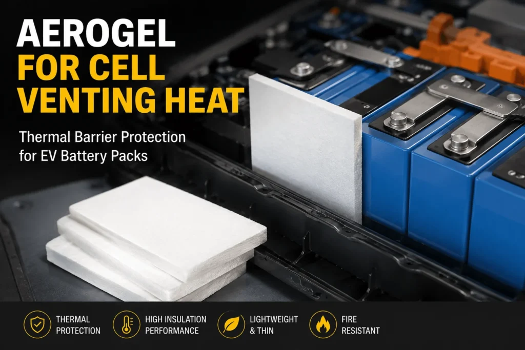
How Does Aerogel Handle Cell Venting Heat in EV Packs?
Table of Contents
When a lithium-ion cell vents, the neighboring cell is not exposed to heat from one direction or by one mechanism. Hot gas can escape at high velocity, flame can wrap around a barrier, and glowing particles can strike surfaces that were never part of the original thermal model. So can a thin aerogel pad still protect the next cell—and where must it be placed to remain effective?
| Aerogel handles cell venting heat by slowing conductive and radiant heat transfer while shielding nearby cells from part of the hot-gas and flame exposure. It does not safely block the cell vent or absorb unlimited jet energy. Effective protection requires aerogel to be positioned outside the pressure-relief opening, combined with controlled vent routing, flame-resistant layers, sealed edges, and validation of the complete module or pack. |
At a Glance
| Design Question | Engineering Answer | Validation Requirement |
| Can aerogel block the vent? | It should not obstruct the safety vent. | Verify vent opening and flow direction. |
| What does it protect against? | Conduction, radiation, and part of hot-gas/flame exposure. | Test the complete laminate and geometry. |
| What else is required? | Vent routing, flame shields, dielectric isolation, and pack controls. | Validate module and pack performance. |
How Aerogel for Cell Venting Heat Works in EV Packs
A cell vent is designed to release internal pressure before the casing or pouch fails in a less controlled way. During severe abuse or thermal runaway, the vented stream may contain hot decomposition gases, electrolyte vapor, smoke, droplets, solid particles, and—if the mixture ignites—a directional jet flame. The thermal load on adjacent components is therefore more complex than simple heat conduction through two cell walls.
Aerogel helps because it offers high thermal resistance in a thin package. A correctly positioned aerogel layer can reduce the rate at which the neighboring cell casing heats, limit line-of-sight radiation, and provide a sacrificial layer between the failure source and sensitive parts. The gained time may support detection, BMS warning, contactor opening, active cooling, controlled venting, or evacuation.
However, aerogel should not be treated as a plug for the cell vent. Blocking a pressure-relief device can raise pressure, redirect the jet, damage the barrier, and produce a more unpredictable event. Aerogel is most effective when it protects the heat-receiving surfaces while the pack architecture gives gases and particles a controlled path away from adjacent cells, busbars, electronics, and the passenger compartment.

Why Aerogel for Cell Venting Heat Is Different From Normal Cooling
Normal battery thermal management removes relatively moderate heat generated during charging, discharging, and fast charging. Thermal interface pads, gels, cooling plates, refrigerant channels, and heat spreaders are deliberately designed to conduct heat away from the cells. Their success is measured by operating temperature and temperature uniformity.
A cell-venting event is the opposite problem. The engineering objective is to prevent an intense, short-duration heat release from reaching the next cell or vulnerable pack component. A low-conductivity aerogel barrier is therefore placed across an unwanted heat path, not across the intended cooling path.
This distinction matters during drawing review. Placing aerogel between the cell bottom and the cold plate may reduce heat rejection and accelerate aging unless the design specifically requires local isolation. Placing a thermal interface pad between adjacent cells can increase cell-to-cell heat transfer. A robust pack normally separates the functions: conductive materials move normal operating heat toward the cooling system, while thermal barriers resist abnormal heat moving toward adjacent cells.
What Cell Venting Heat Actually Contains
The phrase “venting heat” can hide several different hazards. First is sensible heat carried by the gas stream. Even before visible flame, hot gas can rapidly heat a nearby surface by forced convection. Second is chemical energy in flammable vent gases. When mixed with air and ignited, these gases can produce a jet flame that exposes the target to much higher heat flux than conduction alone.
Third is radiation from the hot cell, flame, glowing debris, and heated metal. At elevated temperature, radiation can cross small air gaps and uncovered edges that appear insignificant in a room-temperature drawing. Fourth is particle and droplet impact. Research has documented electrolyte droplets and solid particles being entrained in the vent flow. These can deposit energy locally, ignite, contaminate dielectric surfaces, or damage thin encapsulation films.
Fifth is pressure and flow. A barrier positioned directly over the outlet may be lifted, torn, eroded, or forced against another component. The vent stream can also turn after striking a lid or plate and then run along that surface toward other cells. For this reason, an effective design must consider the three-dimensional flow path after vent opening—not only the straight line between two cells.
What Aerogel Can and Cannot Do During Cell Venting
Aerogel is highly effective at slowing heat through its thickness. Its porous structure limits solid conduction and gas conduction, and suitable formulations can reduce radiative transfer. This makes it valuable on the broad face between prismatic or pouch cells, between cylindrical-cell rows, at module boundaries, and beneath protected structural areas.
Aerogel can also provide short-term shielding against hot gas and flame when the facing, reinforcement, and encapsulation survive the exposure. A reinforced or film-encapsulated part is easier to assemble and less likely to release dust. A hybrid stack can add mica or another high-temperature facing on the jet side and use aerogel behind it as the principal thermal resistor.
Aerogel cannot guarantee that a direct high-velocity jet will remain contained. It cannot compensate for an uncovered vent corridor, an open line of sight to the next cell, a metal busbar that bypasses the barrier, or a cooling plate that carries heat around the pad. It also cannot establish pack compliance from a material datasheet. The complete cell, barrier, frame, vent path, electrical connection, enclosure, sensing system, and test method determine the result.
Where Aerogel for Cell Venting Heat Should Be Positioned
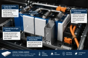
The first rule is to protect the surface that receives the heat, not to obstruct the pressure-relief device that generates the flow. For a top-venting prismatic cell, the primary intercell aerogel pad usually remains between the broad cell faces and stops below the vent opening. A separate top shield, vent guide, or under-lid fire layer manages the upward plume.
The second rule is to interrupt line-of-sight exposure. If the vent from one cell can directly “see” the neighboring cell shoulder, terminal area, busbar, or plastic holder, the design may require a taller edge, a shaped tab, a local mica shield, or a vent channel. Small gaps can become dominant heat paths during flame exposure.
The third rule is to preserve a deliberate exhaust route. Gas should be directed toward a space or channel that can tolerate temperature, pressure, particles, and flame. The barrier should not create a dead end that forces the flow sideways into another cell. Pack covers, manifolds, seals, and pressure-relief features need to be coordinated with the intercell barrier.
The fourth rule is to protect downstream components. Aerogel or hybrid barriers may be placed between the vent corridor and battery-management electronics, contactors, high-voltage junctions, cooling-line fittings, structural adhesives, and enclosure walls. These placements are not substitutes for cell-to-cell barriers; they are additional layers in the safety architecture.
How Prismatic Cells Use Aerogel for Cell Venting Heat
Prismatic cells commonly vent from a designed opening on the top cover. The broad side faces create a large conduction and radiation path, so a near-full-face aerogel pad between adjacent cells is a strong starting point. The pad should cover the active facing area and approach the upper shoulder without covering the safety vent, terminal welds, sensing features, or required electrical clearance.
The upper edge is often the most critical detail. If the aerogel ends too far below the shoulder, flame and hot gas can pass across the exposed region. If it extends into the vent path, it can be displaced or obstruct pressure relief. A stepped profile, reinforced top strip, or separate high-temperature shield can close the radiation path while keeping the outlet clear.
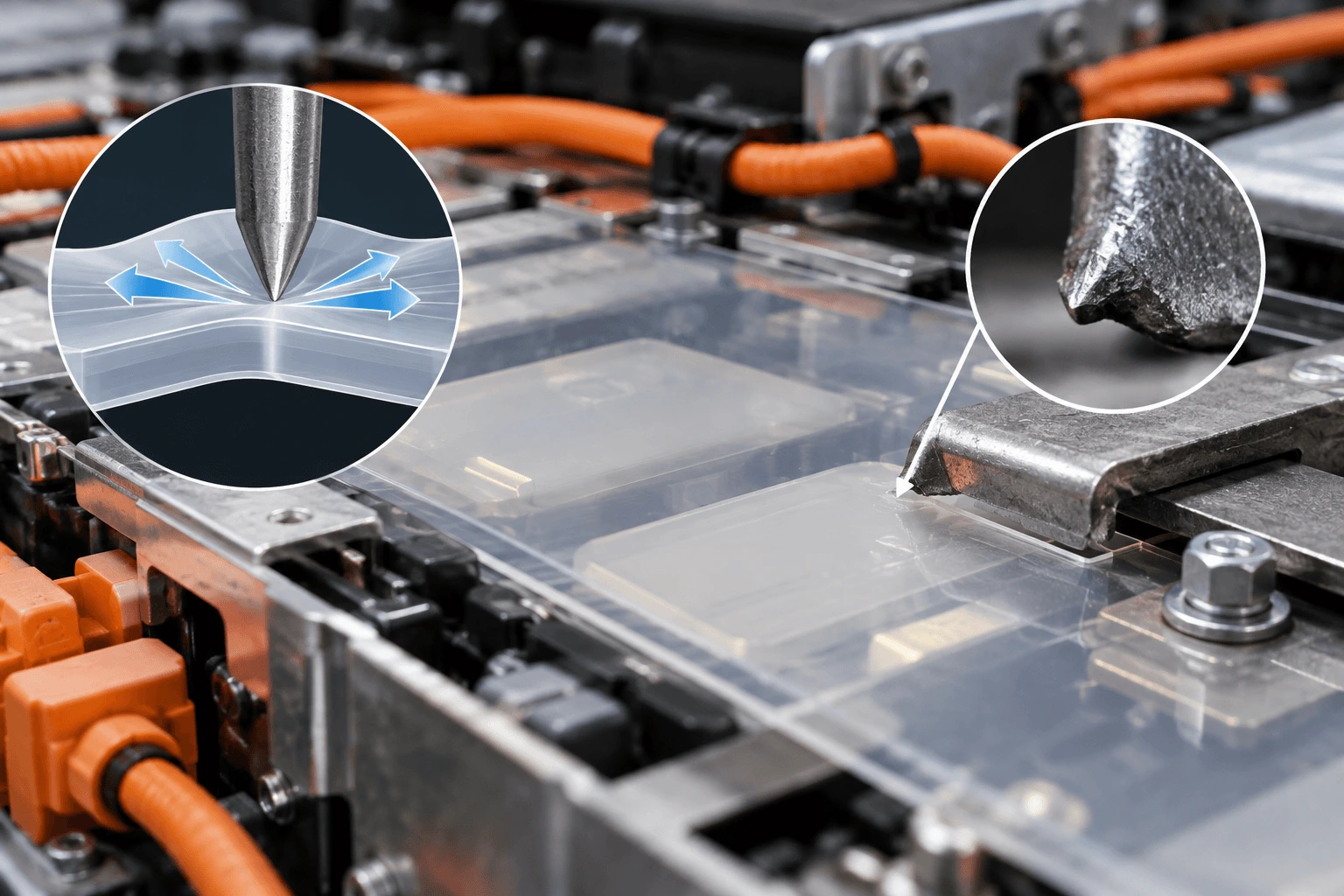
Prismatic modules also use side plates, end plates, busbars, and cooling plates that can conduct heat around the aerogel. Flame-retardant polycarbonate insulation can isolate metal surfaces and provide puncture-resistant dielectric coverage. Mica can be added where direct jet impingement or under-lid fire is expected. Silicone foam can manage cell swelling and stack pressure, provided it does not compress the aerogel below the qualified thickness.
The drawing should define the cell vent keep-out area, aerogel installed thickness, permissible compression range, edge-seal width, adhesive zones, cell-to-pad alignment, top-edge height, and any local flame-facing reinforcement. These dimensions should be verified in the actual module stack, not only as independent flat parts.
How Pouch Cells Use Aerogel for Cell Venting Heat
Pouch cells normally release gas through a weak seal region, a designed vent feature, or a failure opening that can be less geometrically predictable than a rigid metal vent. The cell may also swell significantly before or during failure. This makes pressure distribution and edge protection particularly important.
Aerogel is generally placed across the large active face between pouch cells, while the profile avoids loading the perimeter seal, electrode tabs, and gas pocket. The part should remain flat and free of hard local steps. Thick film overlaps, adhesive ridges, die-cut burrs, or poorly positioned pull tabs can create pressure concentration and damage the pouch during normal cycling.
Because the vent direction may change with pouch deformation, the design should not assume one narrow plume. A top or side shield may need wider coverage than the nominal vent location. Silicone foam can provide controlled compliance and absorb thickness variation, while a thin PC film or insulation sheet can protect the aerogel and maintain dielectric separation.
Validation should include aged and swollen cells or representative mechanical simulators. The aerogel must retain useful thickness and coverage at beginning of life and end of life. A barrier that performs well in an uncompressed coupon may lose much of its benefit after long-term stack pressure.
How Cylindrical Cells Use Aerogel for Cell Venting Heat
Cylindrical cells usually vent axially, but sidewall rupture is also a known severe failure mode. The gaps between cylinders create gas-flow channels, and the tangent contact between cans is much smaller than the broad interface of prismatic cells. Therefore, placing a small flat patch at each contact point is rarely the complete answer.
Aerogel can be configured as row barriers, group partitions, sleeves, shaped inserts, or module-boundary shields. The design objective is to break likely propagation paths while preserving the cooling architecture. If cells vent upward, an under-lid shield or vent manifold may be more important for the jet than the row barrier itself.
Cell holders and busbar systems should be reviewed for bypass paths. Hot gas can travel through triangular voids between cells, and metallic current-collection structures can transfer heat laterally. Hybrid partitions using aerogel plus flame-resistant structural layers may provide a more stable solution than unsupported aerogel felt.
For tightly packed cylindrical arrays, computational fluid dynamics can help identify gas velocity, re-circulation, lid impingement, and downstream exposure. The model should then be checked against module abuse tests because flame, particles, pressure, and changing vent conditions are difficult to predict accurately from simplified inputs.
How Aerogel Handles Jet Flame and Particle Impingement
Direct jet impingement is more severe than a stationary hot-surface test. The barrier may experience localized high heat flux, erosion, pressure, and repeated particle impacts. A low thermal conductivity value does not reveal whether the surface film will split, shrink, melt, or peel away.
The jet-facing surface may require reinforcement. Mica, ceramic-coated fabric, high-temperature film, or another flame-resistant facing can protect the aerogel core. The facing should distribute the local thermal and mechanical load without forming a highly conductive bridge to the protected cell.
Edge construction matters because the jet can enter the laminate from the side. An exposed aerogel edge may shed dust or allow hot gas to penetrate between layers. A controlled edge seal can improve durability, but a thick polymer seam may soften or burn. The seal width, material, and overlap direction should be qualified under representative exposure.
After testing, engineers should inspect not only whether the next cell propagated but also whether the barrier remained in place, whether particles penetrated it, whether the film retracted, and whether the cold-side temperature rose through an edge or attachment point. Post-test failure analysis often reveals the real bypass path.
How Aerogel for Cell Venting Heat Works With PC, Foam, and Mica
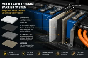
A practical EV barrier is often a multi layer system. Aerogel provides the main resistance to heat moving through the cell-to-cell interface. Flame-retardant polycarbonate provides structural dielectric isolation, puncture resistance, clean assembly surfaces, and shaped extensions around metal hardware. Silicone foam manages gap variation, vibration, swelling, and preload. Mica provides direct flame and high-temperature electrical protection.
One common concept places a reinforced aerogel layer against the large cell face, a thin dielectric skin toward the adjacent metal structure, and a compliant foam zone where thickness variation must be absorbed. At the top vent region, a separate mica or high-temperature shield redirects the plume. The layer order should reflect which side faces the failed cell and which side must remain electrically protected.
The stack should not be made more complex than necessary. Every film, adhesive, foam, and seam adds thickness, tolerance, cost, and possible failure modes. Full-face adhesive may increase contact and alter thermal resistance. A rigid skin may protect the aerogel but create an edge bridge. A soft foam may compress the aerogel more than expected. Test the finished stack at the installed pressure.
How Thickness and Compression Affect Aerogel for Cell Venting Heat
Thicker aerogel generally increases thermal resistance and can extend the time before the neighboring cell reaches a critical temperature. But the relevant value is installed thickness under preload. A nominal 2 mm pad may operate at a very different thickness after module clamping and cell swelling.
Compression can improve contact and prevent gaps, yet excessive compression increases solid contact, reduces the thermal path length, and may damage the porous structure. The supplier should provide compressive stress-strain data, thickness tolerance, recovery, compression set, and thermal data at representative pressure when available.
The module design should define a compression window rather than one nominal number. That window should include cell tolerance, pad tolerance, frame tolerance, assembly preload, temperature, aging, and end-of-life swelling. The thermal test should use the worst credible installed condition.
Local compression is as important as average compression. Adhesive overlap, edge sealing, pull tabs, locating features, and frame ribs can create thin regions. A thermal image or pressure film during prototype assembly can identify areas where the aerogel is over compressed or where a gap opens.
How Adhesives and Encapsulation Affect Venting Protection
Encapsulation improves handling and particulate control, but the film becomes the first surface exposed to hot gas or flame. PET may be suitable for handling and dielectric functions in lower-temperature locations, while PI, coated glass fabric, mica, or other facings may be selected for more severe exposure. Material selection must match the actual jet and flame environment.
Pressure-sensitive adhesive should be used strategically. Full-face adhesive can simplify assembly but may introduce a continuous polymer path and change the stack’s fire behavior. Zoned or perimeter adhesive can preserve more of the aerogel’s active area, although it must still prevent movement during assembly and vibration.
Adhesive keep-out zones should be defined around vents, terminals, welds, cooling interfaces, and high-temperature edges. Squeeze-out under compression can contaminate electrical surfaces or bridge a designed gap. The liner split and pull tab should support error-free placement without forcing operators to touch or flex the barrier excessively.
The final laminate should be qualified as a complete part. A core aerogel certificate does not automatically cover the film, adhesive, ink, reinforcement, or converter process. Likewise, an UL 94 rating is a small-scale material flammability classification and does not prove resistance to a battery jet flame or pack-level thermal propagation.
DFM for Die-Cut Aerogel Cell-Venting Barriers
Die-cut design should begin with the cell and module stack-up, not with a rectangular material blank. Provide the converter with the cell outline, active face, vent keep-out zone, terminal geometry, frame and rail features, cooling contact, compression direction, assembly sequence, and required orientation.
Critical drawing dimensions include overall profile, protected area, vent clearance, top-edge height, edge-seal width, adhesive location, liner split, pull-tab location, cutout radii, minimum web width, locating holes, flatness, and installed thickness. Special characteristics should be linked to inspection methods and process capability requirements.
Aerogel can be crushed or contaminated during cutting. Tool geometry, blade sharpness, support liner, cutting pressure, web tension, dust extraction, and part handling must be controlled. A clean cut is not only cosmetic: broken encapsulation or exposed powder may reduce dielectric cleanliness, handling reliability, and barrier coverage.
Packaging should keep parts flat and prevent compression before assembly. International shipments may encounter humidity, temperature variation, and vibration. Trays, interleaves, orientation labels, and lot traceability should be defined during prototype development rather than added after production approval.
How to Validate Aerogel for Cell Venting Heat
Validation should proceed from material to pack.
First, screen the aerogel and finished laminate for thickness, thermal conductivity, high-temperature dimensional stability, compression behavior, dielectric strength, flame response, adhesive peel, dust release, and chemical compatibility.
Second, perform directional heat and impingement coupon tests. Expose the intended jet-facing side to a hot plate, burner, radiant panel, or calibrated gas/flame source. Measure cold-side temperature, film damage, edge penetration, mass loss, and structural integrity. These tests are useful for comparing stack-ups but are not equivalent to cell venting.
Third, use cell simulators or real two-cell tests to reproduce the geometry, compression, vent direction, lid spacing, and electrical structures. Instrument the protected cell face, upper shoulder, busbar, edge, and downstream components. Record the clock from defined events such as vent opening, trigger-cell runaway, or flame appearance.
Fourth, perform representative module thermal-propagation testing using the project-defined trigger and worst-case SOC. Observe propagation, warning signals, gas routing, flame outside the enclosure, electrical isolation, and structural response. Repeat across production tolerances and credible aging conditions.
Fifth, confirm the complete pack or vehicle safety strategy. UN Regulation No. 100 thermal-propagation provisions are based on warning and hazardous-condition performance at the REESS or vehicle level. The aerogel part contributes to that result but cannot independently establish regulatory compliance.
Industry Insight: Vent Management Is Becoming a Separate Design Discipline
As EV packs become more integrated, the distance between cells, structural members, cooling plates, and covers is shrinking. Cell-to-pack and cell-to-chassis layouts can reduce module mass, but they also remove some traditional compartment boundaries. A single vent event may interact with a larger continuous structure.
For this reason, thermal-safety teams are separating two engineering questions: how to slow heat through the cell interface, and how to route gas, flame, and particles. Aerogel addresses the first problem strongly and supports the second when used as a protected shield. It does not replace a dedicated vent-management architecture.
Supplier qualification is also moving beyond nominal conductivity. OEMs and pack makers increasingly request installed-thickness data, heat-flux curves, impingement durability, edge integrity, compression aging, finished-part flame evidence, and module test support. Converters that can control multilayer lamination, adhesive zoning, precision die cutting, cleanliness, traceability, and rapid prototype changes are becoming more valuable.
The commercial implication is clear: buyers are not purchasing only an aerogel sheet. They are purchasing a repeatable barrier geometry that survives assembly and creates measurable safety margin in the target pack.
Common Aerogel Cell-Venting Design Mistakes
The most serious mistake is placing the barrier directly over the safety vent without a validated pressure and gas-flow plan. This can redirect the event toward another cell or damage the enclosure.
Another mistake is designing only for conduction through the cell face. Vent gas, flame, particles, radiation, and metal bridges can dominate. The thermal model and abuse test should include the top region, edges, lid, busbars, and exhaust path.
Teams also confuse free-state thickness with installed thickness. A pad that is over compressed at end of life may provide far less thermal resistance than the prototype coupon. Conversely, an unrecompensed pad may move, wrinkle, or leave an air channel.
Using a material-level UL 94 classification as proof of jet-flame resistance is another error. UL 94 evaluates small specimens under controlled ignition conditions. It is a useful preselection requirement for polymeric layers, but the battery barrier and pack must be tested under application-relevant conditions.
Finally, engineering changes are sometimes made after validation without repeating the relevant tests. Changing the aerogel core, encapsulation film, adhesive, supplier, thickness, edge seal, compression, vent clearance, or die-cut geometry can change the result. The complete converted part needs disciplined change control.
How to Specify Aerogel for Cell Venting Heat in an RFQ
A high-quality RFQ should identify the cell format, chemistry, capacity, dimensions, nominal and worst-case state of charge, vent location, expected vent direction, module layout, protected components, available thickness, compression range, cooling interface, and electrical-clearance requirements.
Define the safety objective. Examples include preventing adjacent-cell runaway for a specified observation period, limiting the protected-cell surface temperature, keeping flame away from a busbar or pack cover, maintaining dielectric isolation after exposure, or meeting a defined module or pack propagation criterion.
Provide a 2D drawing or CAD file with critical dimensions and keep-out zones. State whether the part requires PET or PI encapsulation, mica facing, PC reinforcement, silicone foam, adhesive backing, liner split, pull tab, printed identification, cleanliness limits, and special packaging.
Request material and finished-part documentation: thermal data, thickness tolerance, compression curve, high-temperature shrinkage, dielectric data, flame classification at the relevant thickness, adhesive peel, chemical compatibility, lot traceability, inspection plan, change-control process, prototype lead time, and annual-volume assumptions.

How Boost Insulation Can Support EV Venting-Barrier Projects
Boost Insulation supports custom EV and energy-storage insulation parts using aerogel, flame-retardant polycarbonate, silicone foam, mica, dielectric films, pressure-sensitive adhesives, and precision die-cut conversion. This allows the barrier, structural insulation, pressure-management layer, and assembly features to be reviewed as one functional stack.
Engineering support can include material selection, laminate design, vent keep-out review, adhesive zoning, edge encapsulation, liner and pull-tab design, tolerance analysis, rapid prototypes, inspection planning, packaging, and volume-production DFM.
For a useful review, send the cell or module drawing, target installed thickness, compression range, vent direction, protected surfaces, material restrictions, flame and dielectric requirements, validation method, expected annual volume, and the current failure or assembly concern. The first prototype should be treated as an input to testing—not as proof of pack-level performance.
| Need a vent-path and thermal-barrier DFM review?
Send Boost Insulation your cell or module drawing, vent location, installed thickness, compression range, protected surfaces, material restrictions, and validation target. The engineering team can review aerogel, PC insulation, silicone foam, mica, film, adhesive, and die-cut options for a prototype quotation. |
Frequently Asked Questions
Can aerogel safely cover a battery cell vent?
Normally, no. The pressure-relief opening should remain functional. Aerogel should protect adjacent surfaces while a validated vent channel or shield directs gas, flame, and particles away from neighboring cells.
Can aerogel stop a battery jet flame?
Aerogel can reduce heat transfer and may contribute to flame shielding, but direct jet exposure can erode or damage the laminate. Severe jet locations often need reinforced facings, mica, or a dedicated flame shield.
Should aerogel be placed between the cell and cold plate?
Not when that interface is intended to conduct normal operating heat into the cooling system. Aerogel should interrupt unwanted cell-to-cell or failure heat paths unless local bottom isolation is specifically designed and validated.
Is full-face aerogel coverage always required?
Near-full-face coverage is a strong starting point for prismatic and pouch cells. Partial coverage may be used only when thermal mapping and abuse testing show that the uncovered regions do not become bypass paths.
How thick should an aerogel venting barrier be?
There is no universal thickness. Select thickness from the required delay, heat flux, cell energy, installed compression, available space, and module test results. Specify installed rather than only free-state thickness.
Does UL94 V-0 prove the barrier can resist venting heat?
No. UL94 V-0 is a small-scale flammability classification for a material at a specified thickness. It does not establish battery jet-flame resistance, propagation delay, or pack compliance.
Can silicone foam replace aerogel near a vent?
Silicone foam is useful for compression, sealing, vibration, and gap control, but it usually does not provide the same thin-section thermal resistance as aerogel. The two materials often perform complementary functions.
What should be sent to request a custom sample?
Send the cell or module drawing, vent location, barrier profile, installed thickness, compression range, adhesive zones, facing requirements, target test, annual volume, and any cleanliness or packer
Technical References
- United Nations Economic Commission for Europe. UN Regulation No. 100, Revision 3: thermal-propagation warning and REESS safety requirements. Source
- Quip, M. et al. “Research Progress in Thermal Runaway Vent Gas Characteristics of Lithium-Ion Batteries.” Batteries, 2023. Source
- Burnies, P. J. et al. “Review of Gas Emissions From Lithium-Ion Battery Thermal Runaway Failure.” Current Opinion in Green and Sustainable Chemistry, 2024. Source
- Wang, G. et al. “Revealing Particle Venting of Lithium-Ion Batteries During Thermal Runaway.” transportation, 2023. Source
- Chen, H. et al. “Comprehensive Analysis of Thermal Runaway and Sidewall Rupture of High-Specific-Energy Cylindrical Cells.” Applied Energy, 2023. Source
- Wong, S. K. et al. “Mitigating Thermal Runaway Propagation in High-Specific-Energy Lithium-Ion Battery Modules Using Nanofiber Aerogel.” Energy, 2024. Source
- UL Solutions. “Combustion (Fire) Tests for Plastics” and UL 94 flame-classification guidance. Source
- Boost Insulation. EV battery insulation, aerogel, mica, PC insulation, silicone foam, and precision die-cut solutions. Source
Related Posts:
How Does PC Insulation Resist Puncture in EV Batteries?
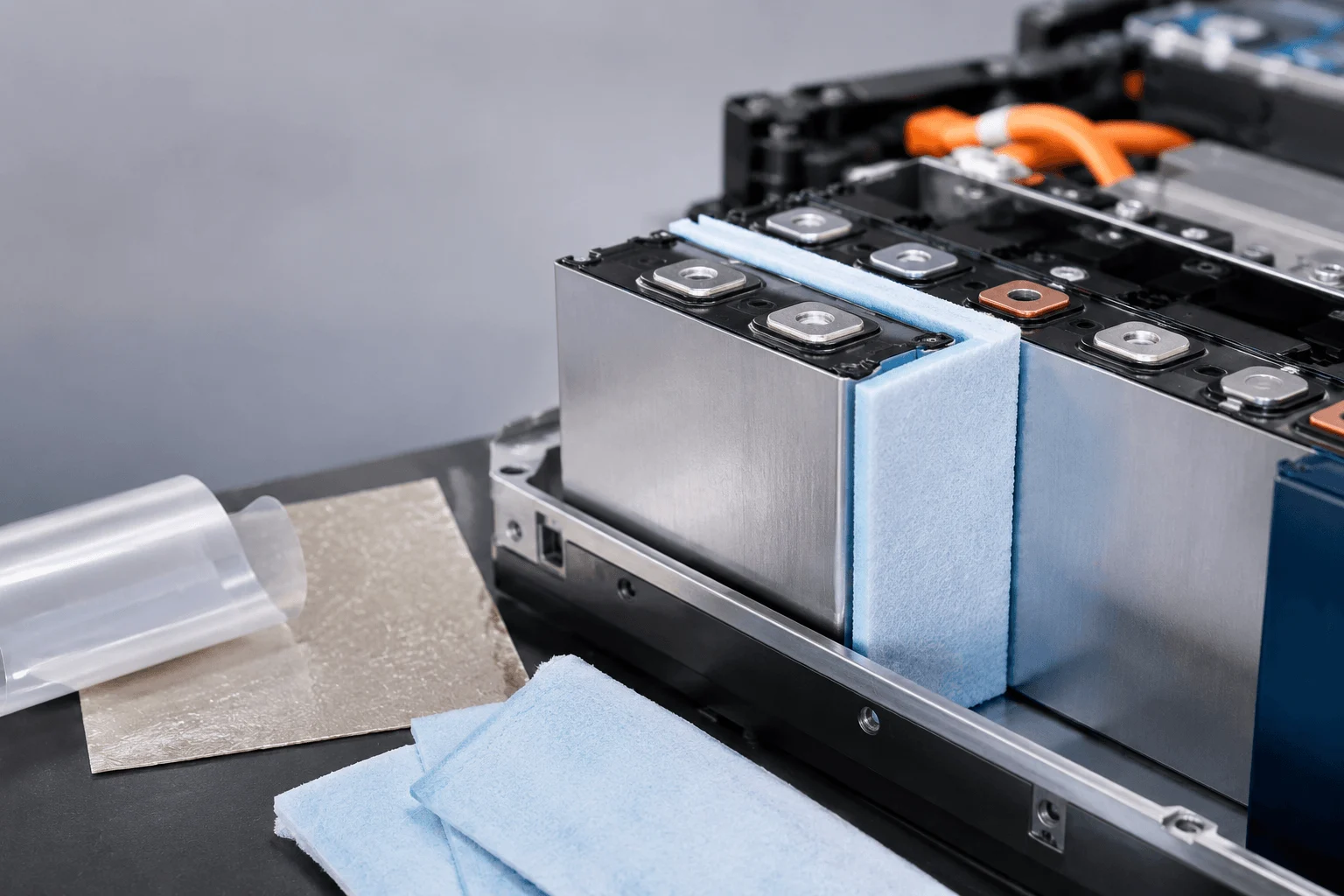
How Do You Select Aerogel Thickness Between Cells?
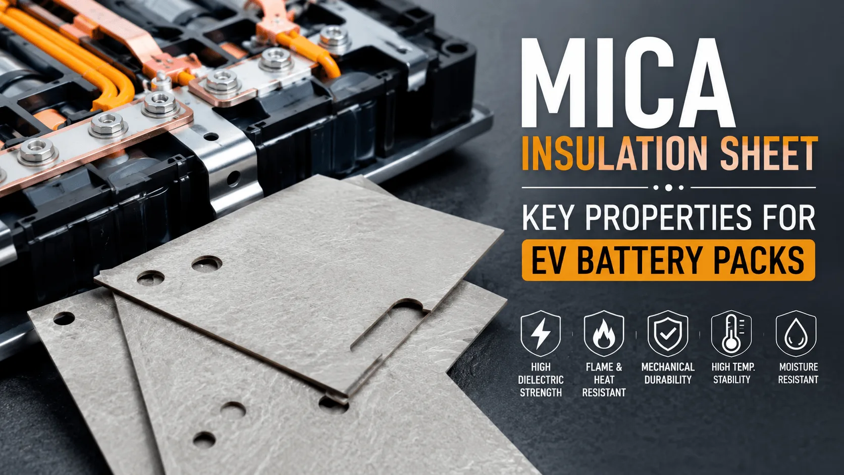
What Properties Make a Mica Insulation Sheet Effective?

What Is ESS Energy Storage Solution & How It Works?
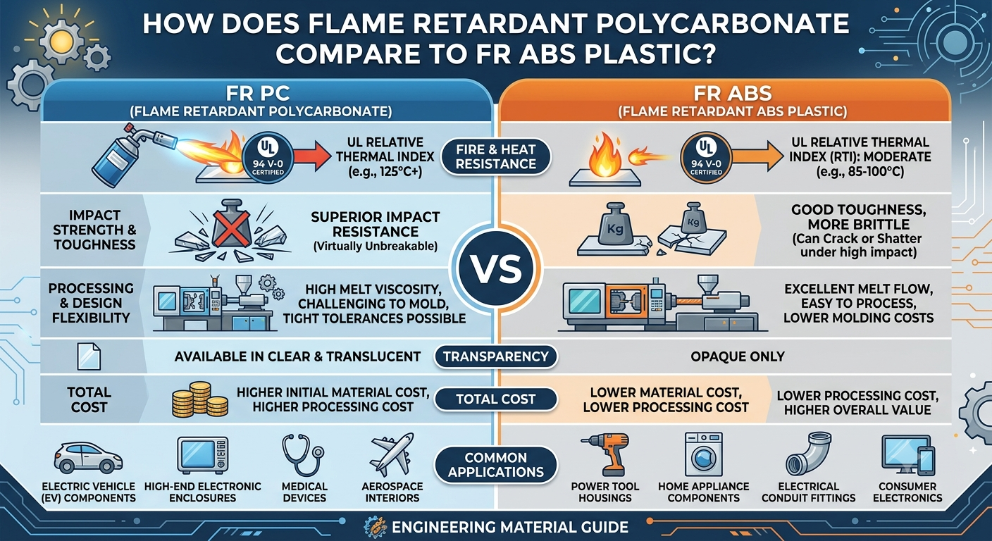
How Does Flame Retardant Polycarbonate Compare to FR ABS Plastic?
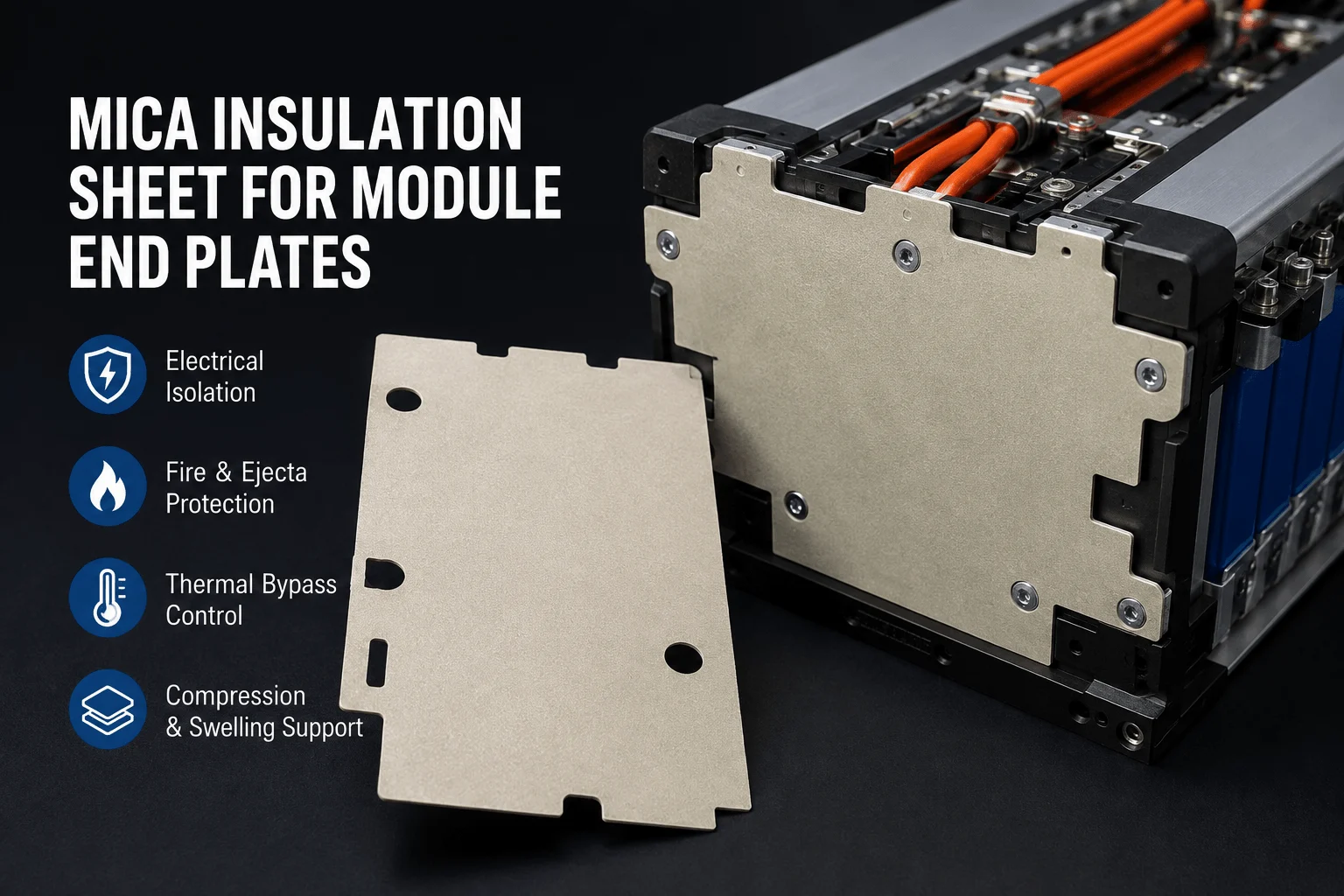
How Is a Mica Insulation Sheet Used on Module End Plates?
 betty wong
