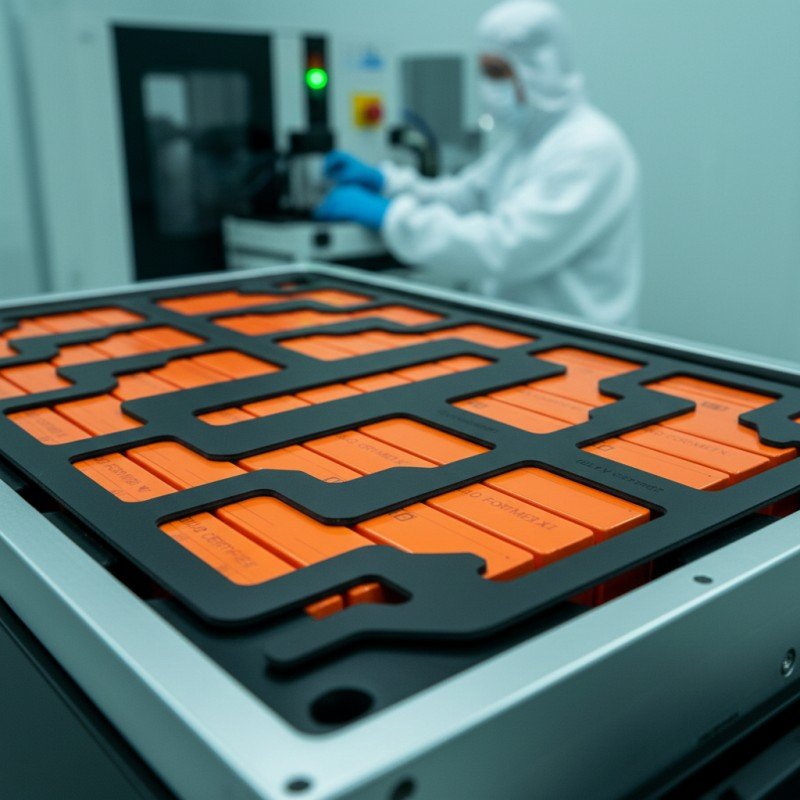
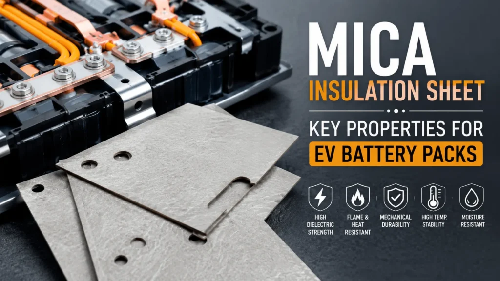
What Properties Make a Mica Insulation Sheet Effective?
Table of Contents
A mica sheet can look perfectly flat, pass a basic voltage test, and still fail in the battery pack because its binder softens, its edge cracks around a terminal cutout, or its adhesive releases when a nearby cell vents. So which properties actually make mica effective—and which datasheet values can create false confidence when they are reviewed without the finished part, installation pressure, heat path, and failure scenario?
| An effective mica insulation sheet combines high dielectric strength and insulation resistance with high-temperature structural integrity, flame and arc resistance, controlled thermal performance, mechanical durability, dimensional stability, moisture resistance, and clean die-cut edges. For EV batteries, these properties must remain acceptable at the minimum production thickness and after aging, vibration, humidity, adhesive lamination, and representative thermal-runaway exposure. No single property or generic mica grade is sufficient. |
Effective Mica Insulation Sheet Properties at a Glance
| Property | Why It Matters | What to Specify | What to Validate |
| Electrical | Prevents breakdown, leakage, and shorts | Dielectric strength, insulation resistance, creepage geometry | Finished part after humidity and aging |
| High temperature and flame | Maintains a physical barrier during failure | Exposure duration, burn-through, shrinkage, retained integrity | Torch, heat-flux, vent, module, and pack tests |
| Mechanical | Survives cutting, assembly, vibration, and impact | Strength, puncture, bend radius, edge quality | Production-intent geometry and mounting |
| Environmental and manufacturing | Maintains consistency through life and production | Moisture, adhesion, dimensions, particles, traceability | Aged laminate, die-cut parts, and process capability |
What Properties Make a Mica Insulation Sheet Effective?
The most effective mica sheet is not necessarily the grade with the highest maximum-temperature claim or the highest dielectric-strength number. It is the grade whose electrical, thermal, fire, mechanical, and manufacturing properties work together in the actual battery location.
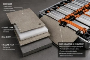
For example, a busbar insulator may prioritize dielectric strength, puncture resistance, thinness, edge quality, and creepage geometry. An under-lid thermal-runaway barrier may prioritize flame impingement resistance, dimensional stability, low shrinkage, attachment, and post-fire integrity. A cell-to-cell composite may require mica to resist flame while aerogel provides most of the thermal resistance and silicone foam manages swelling
The correct evaluation unit is the finished converted component. Mica mineral type, mica-paper quality, binder content, reinforcement, adhesive, film, foam, thickness, density, edges, cutouts, bends, and assembly method can change the result. A certificate for the raw sheet does not automatically qualify a laminated die-cut part.
Why Dielectric Strength Matters in a Mica Insulation Sheet for EV Battery Packs
Dielectric strength describes a material’s ability to resist electrical breakdown through its thickness under defined test conditions. It is essential near busbars, terminals, fuse assemblies, contactors, service disconnects, module frames, pack covers, and grounded metal.
ASTM D149 is commonly used to determine dielectric breakdown voltage and dielectric strength of solid electrical insulating materials at commercial power frequencies. The test is useful for material comparison, but the result depends on specimen thickness, electrode geometry, conditioning, voltage ramp, environment, and failure criterion.
A high laboratory value does not remove the need for design margin. Production parts contain holes, narrow webs, stamped edges, adhesive zones, and possible surface contamination. Electrical stress may concentrate at a metal burr or sharp conductor rather than distribute uniformly across the sheet.
Specify the required test voltage, dwell time, leakage limit, minimum production thickness, temperature, humidity conditioning, and post-aging requirement. Use the exact finished laminate for qualification whenever the mica is backed with film, foam, adhesive, or another structural layer.
Insulation Resistance and Surface Tracking Performance
Dielectric strength addresses breakdown, while insulation resistance describes how strongly the material and its surfaces resist leakage current. Both matter in high-voltage EV packs, especially after humidity, contamination, electrolyte exposure, or thermal aging.
Mica is naturally associated with strong electrical insulation, but a commercial sheet contains binders and may collect dust, adhesive residue, fingerprints, metal particles, or ionic contamination during converting and assembly. These surface conditions can reduce effective resistance.
Tracking risk is influenced by voltage, moisture, contamination, surface path, material chemistry, and geometry. A mica barrier can extend creepage distance, but a wet edge, conductive adhesive residue, or fastener bridge may shorten the real path.
Incoming and production controls should include surface cleanliness, edge inspection, controlled packaging, and electrical testing at a frequency appropriate to the risk. The design should also prevent condensed moisture or vented electrolyte from remaining on the high-voltage surface.
High-Temperature Structural Integrity of Mica Insulation
One of mica’s most important battery properties is its ability to remain physically present under severe heat. Many polymer films offer excellent dielectric performance during normal operation but may shrink, soften, melt, carbonize, or lose mechanical strength during thermal runaway.
The mica mineral can remain stable at very high temperature, but the finished sheet is governed by its weakest layer. The binder may decompose, the glass carrier may lose adhesion, the pressure-sensitive adhesive may release, and an unsupported sheet may crack or fall away.
A maximum-temperature value should always be separated into continuous service, short-duration exposure, and direct-flame or torch exposure. The test report should identify duration, heat source, distance, support condition, specimen thickness, and pass criteria.
Post-exposure integrity is often more important than whether the sample briefly survives. Inspect shrinkage, curling, cracking, delamination, erosion, loss of thickness, attachment, and retained dielectric separation after the heat source is removed.
Flame Resistance and Burn-Through Performance
During a severe cell failure, mica may face direct flame, hot gas, electrolyte droplets, and solid ejecta. Effective flame protection requires more than a low flammability rating.
A useful mica barrier should resist rapid burn-through, remain over the protected area, and reduce the heat and flame reaching the cold side. Rigid or glass-reinforced constructions can improve resistance to particle impact and maintain coverage across unsupported spans.
Product-specific data can demonstrate capability, but it should not be generalized. For example, Saint-Gobain’s CHR FR1000 mica tape data sheet reports product-specific flame-torch and dielectric properties. Those results apply to that exact tape construction and test conditions, not to every mica sheet or converted part.
For pack lids, vent corridors, and module partitions, use heat-flux, torch, burner, hot-gas, particle, or cell-vent tests that reproduce the intended exposure. Measure burn-through time, cold-side temperature, damaged area, edge penetration, and post-test attachment.
Arc Resistance and Electrical Fault Containment
Mica is also valued around busbars and switching components because it can maintain electrical separation under heat and may help contain the effects of an arc or short circuit.
Arc performance depends on the gap, voltage, current, conductor geometry, contamination, pressure, and surrounding materials. A mica sheet can shield a metal surface and reduce direct exposure, but it cannot compensate for inadequate clearances or an uncontrolled conductor path.
The design should avoid exposed metal at holes and edges. Folded tabs, overlap zones, or a mica-polycarbonate laminate may be used to preserve dielectric coverage around complex hardware.
Representative electrical-fault testing should be considered for critical junction boxes, fuse zones, and service disconnects. The purpose is to evaluate the complete assembly, not only a flat mica coupon.
Thermal Conductivity and Thermal Resistance
Mica is a thermal barrier, but it is not normally selected because it has the lowest thermal conductivity available. Aerogel generally provides greater thermal resistance per millimeter for broad cell-to-cell isolation.
Mica’s battery advantage is the combination of heat resistance, flame integrity, and dielectric performance. In many locations, remaining intact during a fire is more important than having the lowest room-temperature conductivity.
Thermal performance should be evaluated as installed thermal resistance, which depends on conductivity and thickness. Edges, holes, metal fasteners, busbars, frames, and cooling plates may create parallel heat paths that bypass the sheet.
For cell-to-cell use, compare mica alone with mica-aerogel, mica-foam, and alternative stacks under the same pressure and heat exposure. For lid protection, prioritize cold-side temperature and burn-through rather than relying on a single conductivity number.
Thickness and Thickness Uniformity
Thickness affects dielectric margin, stiffness, flame resistance, burn-through time, thermal resistance, mass, flexibility, and cost. The best thickness is application-specific and should be selected from validated performance, not a generic EV rule.
A thin sheet may be suitable for busbar wrapping or local insulation. A thicker rigid sheet may be required for an under-lid panel or module wall. A cell-interface barrier may use a thin mica facing over aerogel or foam.
Uniformity matters because the thinnest production region controls the electrical and thermal margin. Pressing, grinding, binder distribution, lamination, adhesive, and die-cut compression can create local variation.
Specify nominal and minimum thickness, measurement method, measuring pressure, sampling plan, and tolerance. Qualification samples should represent the minimum allowed finished-part thickness.
Mechanical Strength and Puncture Resistance
An effective mica sheet must survive handling, die cutting, liner removal, installation, clamping, vibration, impact, and long-term pack movement. A high-temperature material that cracks during assembly does not provide a reliable barrier.
Relevant properties may include tensile strength, flexural strength, puncture resistance, tear resistance, impact behavior, and edge durability. The required property depends on whether the part is a rigid panel, flexible tape, folded barrier, or multilayer pad.
Glass fabric or other reinforcement can improve strength and dimensional control. Flame-retardant polycarbonate may add puncture resistance and protect mica around sharp metal edges.
Mechanical tests should include the final cutouts and support conditions. A large panel with multiple holes can fail differently from a small rectangular coupon.
Flexibility and Minimum Bend Radius
Some battery locations require mica to follow a curved busbar, stamped pack lid, enclosure corner, or cable transition. Flexibility allows the barrier to conform without creating gaps.
Flexibility is controlled by mica-paper structure, mineral type, binder chemistry, reinforcement, thickness, and backing. A sheet may feel flexible in hand but crack after repeated bends, cold-temperature assembly, or heat aging.
Define the minimum bend radius and whether the bend is formed once or cycled repeatedly. Tight creases should be avoided unless the exact grade is designed and tested for folding.
For complex curves, flexible mica tape or a thin mica-film laminate may be more reliable than forcing a rigid board into shape. A segmented design can also reduce stress while maintaining coverage.
Dimensional Stability and Low Shrinkage
Dimensional stability allows the mica barrier to retain its coverage around vents, terminals, busbars, and pack edges during heat, humidity, and aging.
Shrinkage can expose a conductor or create a flame path. Curling can lift the barrier away from the substrate. Differential expansion between mica, film, polycarbonate, aluminum, steel, and adhesive can create warpage or delamination.
Test length, width, flatness, hole location, and curl after thermal aging and cycling. Large under-lid parts should be evaluated on the intended substrate because the support structure affects deformation.
Designs with dissimilar layers should use balanced lamination where practical. Adhesive coverage, liner removal, storage humidity, and conversion tension can also influence flatness.
Muscovite and Phlogopite Mica Properties
Muscovite and phlogopite are the two mica mineral types most commonly used in technical insulation. Muscovite is widely associated with strong dielectric performance, while phlogopite is often selected for higher-temperature exposure.
The mineral type is only one design variable. Mica-paper quality, flake orientation, binder, reinforcement, pressing, thickness, and surface treatment can change the finished result.
A busbar part may prioritize dielectric strength, thinness, and punching quality. An under-lid flame barrier may prioritize high-temperature integrity and burn-through resistance. The best grade for one location may be inefficient or unnecessarily expensive for another.
The drawing and PPAP documentation should identify the exact approved grade and source. A substitution from muscovite to phlogopite—or between suppliers—should trigger engineering review rather than automatic approval.
Binder Chemistry and Binder Content
Commercial mica sheets rely on a binder to hold mica paper or flakes together. Binder chemistry influences flexibility, stiffness, room-temperature strength, heat resistance, smoke, flame behavior, and delamination.
Silicone binders are often associated with high-temperature flexibility. Epoxy systems can create strong rigid boards. Other resin systems may be used for specialized electrical or mechanical requirements.
Increasing binder content can improve toughness and conversion yield but may reduce the proportion of heat-stable mineral and increase organic decomposition. Too little binder can create weak edges, dust, and delamination.
Ask for binder type, nominal content, cure condition, and change-control requirements. Post-fire testing should inspect whether the mica remains supported after the binder has degraded.
Reinforcement and Laminate Construction
IEC standards for mica-based electrical insulation recognize that mica paper can be combined with glass fabric, polyester film, epoxy systems, and other components to create specific materials. This reflects the reality that mica is often part of a laminate rather than a standalone sheet.
Glass backing improves tensile strength and handling. Polymer films provide clean surfaces and additional dielectric protection. Polycarbonate can add structure and puncture resistance. Silicone foam can add compression management, and aerogel can increase thermal resistance.
Every reinforcement also changes thickness, density, heat transfer, flame response, flexibility, and die-cut behavior. The finished construction should therefore have its own controlled part number and test evidence.
Avoid approving a laminate from separate certificates for its individual layers. Adhesion, seams, overlaps, and edge exposure create interactions that are not visible in standalone material reports.
Moisture Resistance and Environmental Aging
EV battery parts experience humidity, temperature cycling, condensation risk, vibration, and possible exposure to coolant, electrolyte vapor, cleaning agents, and manufacturing chemicals.
Moisture can reduce surface insulation resistance, weaken adhesive, swell a carrier, promote tracking, or change the interface between mica and its binder. The mica mineral itself may remain stable while the laminate fails at an adhesive or reinforcement layer.
Qualification should include humidity aging, thermal cycling, heat aging, low-temperature exposure, and relevant chemical compatibility. Electrical and mechanical tests should be repeated after conditioning rather than performed only on new dry samples.
Packaging and storage matter. Flat, dry, clean storage reduces curl, contamination, and moisture variation before die cutting and assembly.
Surface Quality, Cleanliness, and Low Particle Release
Cleanliness is a functional property in a high-voltage battery pack. Loose mica particles, glass fibers, adhesive strings, metal dust, or liner fragments can contaminate cells, busbars, connectors, and optical inspection systems.
Surface defects such as cracks, blisters, resin-rich spots, voids, scratches, or embedded contamination may reduce dielectric and flame performance. A smooth surface also improves adhesive contact and automated placement.
Define cosmetic and functional inspection limits. Vision inspection can identify cracks and missing features, while controlled cleanroom or clean-area processing can reduce particle contamination.
Packaging should prevent abrasion and bending. Interleaving, trays, orientation marks, and protective liners may be necessary for large or fragile parts.
Die-Cut Edge Quality and Crack Resistance
The die-cut edge is frequently the weakest part of a mica component. Layered materials can split, delaminate, chip, or develop microcracks around holes and sharp internal corners.
Edge defects can reduce creepage distance, expose adhesive, release particles, or provide a direct flame path. Narrow bridges and terminal windows deserve particular inspection.
Design larger internal radii, adequate edge distances, and sufficient web width. Tool sharpness, die clearance, cutting pressure, support liner, and stripping method should be optimized for the exact grade.
A converter should establish measurable edge criteria and inspect representative parts under magnification. Prototype samples must use the production-intent laminate and geometry.
Adhesion and Attachment Reliability
A high-performing mica sheet cannot protect the pack if it shifts, lifts, or falls away. Attachment may use pressure-sensitive adhesive, silicone adhesive, structural bonding, clips, fasteners, compression, or a combination.
Adhesive selection depends on substrate surface energy, temperature, humidity, flame exposure, vibration, chemical environment, and assembly process. Aluminum, coated steel, polycarbonate, silicone foam, and mica surfaces do not behave identically.
Full-face adhesive maximizes initial contact but adds mass, polymer content, and a continuous heat-transfer interface. Selective zones can reduce these effects while maintaining alignment.
Test peel, shear, creep, liner release, and post-aging adhesion. For high-temperature barriers, confirm that mechanical retention or the charred adhesive condition keeps the mica over the protected zone during the event.
Flammability Ratings and Their Limits
Some mica laminates, tapes, films, adhesives, or composite parts carry UL 94 classifications. These ratings can support material screening and customer documentation.
UL explains that V-0, V-1, V-2, VTM, and other ratings use defined small-scale specimen tests. VTM-0 is not equivalent to V-0 because the methods differ. The rating also depends on the exact material and thickness.
A UL 94 result does not establish resistance to battery vent flame, particle impact, burn-through, thermal-runaway propagation, or pack-level compliance. Mica’s inorganic content does not automatically qualify every binder and adhesive construction.
Technical marketing should identify the exact rated layer and thickness. Application claims should be supported by representative fire and battery tests.
Property Priorities by EV Battery Location
Between cells, prioritize flame integrity, thermal resistance of the complete stack, compression compatibility, smoothness, edge coverage, and no interference with vents or cooling.
At busbars and high-voltage junctions, prioritize dielectric strength, insulation resistance, puncture resistance, creepage geometry, clean edges, adhesion, and arc-related protection.
Under the pack lid, prioritize burn-through, hot-gas and particle resistance, dimensional stability, broad-area attachment, low shrinkage, and coverage around ribs, fasteners, seals, and openings.
At module walls and pack perimeters, prioritize stiffness, impact resistance, flame integrity, electrical isolation, low warpage, and reliable mounting across large spans.
A single generic mica specification cannot efficiently serve all four locations. Build a small approved material family with location-specific grades and validation.
How to Validate Mica Insulation Sheet Properties
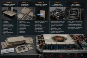
Level 1 tests the raw sheet and laminate: thickness, areal mass, dielectric strength, insulation resistance, mechanical strength, flexibility, high-temperature shrinkage, moisture resistance, and flame response.
Level 2 tests the finished die-cut part: dimensions, edges, holes, bends, delamination, puncture, adhesive peel, liner release, flatness, cleanliness, and packaging.
Level 3 uses heat-flux, burner, torch, hot-gas, particle, or impingement testing. Measure burn-through, cold-side temperature, damaged area, edge penetration, and post-test integrity.
Level 4 tests the representative module with the actual cell format, state of charge, vent direction, busbars, cooling system, compression, and enclosure. Record propagation timing, flame, gas, pressure, voltage, electrical isolation, and warning behavior.
Level 5 confirms pack or vehicle performance. UNECE thermal-propagation work focuses on robust system-level assessment; no mica datasheet can substitute for complete REESS validation.
DFM Requirements for an Effective Mica Insulation Sheet
The material and part geometry must be developed together. Provide the converter with the actual pack, module, busbar, or lid drawing—not only a rectangular mica outline.
Critical requirements include thickness, minimum webs, internal radii, hole tolerances, edge distances, bend zones, adhesive pattern, liner split, pull tabs, flatness, cleanliness, orientation, labeling, and packaging.
Flatbed die cutting, rotary die cutting, CNC cutting, stamping, and other processes may be used depending on thickness, reinforcement, volume, and geometry. Laser processing requires careful evaluation because heat can affect binder and edge quality.
Prototype the complete laminate before design freeze. Review assembly ergonomics, liner removal, positioning, cracking, particle release, and removal force as well as dimensional inspection.
Industry Insight: Effective Mica Is Becoming a Multifunctional Component
The EV industry is moving beyond simple flat mica boards. New designs use thin adhesive mica tapes, large under-lid liners, mica-plus-silicone-foam compression pads, mica-aerogel thermal barriers, and mica-polycarbonate dielectric structures.
The trend is driven by higher pack integration, larger cells, fast charging, reduced module walls, and tighter space. The insulation part must provide more functions with less thickness and fewer assembly steps.
Buyers are also shifting from generic temperature claims to evidence that reflects the installed component: burn-through curves, post-flame dielectric integrity, compression aging, edge durability, clean conversion, and module-level testing.
For a precision converter, the commercial value is not the mica roll itself. It is the ability to select the grade, design the laminate, control edges and adhesive, produce rapid prototypes, and maintain traceability through automotive production.
How to Specify an Effective Mica Insulation Sheet
The specification should identify mica type, natural or reconstituted construction, binder, reinforcement, rigid or flexible format, thickness and tolerance, areal mass, dielectric strength, insulation resistance, service and short-term temperature, flame or burn-through requirement, moisture conditioning, and approved source.
Add the application location and failure exposure: busbar, cell interface, module wall, pack lid, vent corridor, junction box, fuse, or service disconnect.
The drawing should define protected zones, creepage paths, vent keep-outs, holes, radii, minimum webs, bends, adhesive zones, liner design, edge quality, cleanliness, labeling, and packaging.
Define validation, sampling, certificates, PPAP, lot traceability, and formal change control. Any change to mica paper, binder, reinforcement, film, adhesive, thickness, or converter should receive engineering review.
RFQ Checklist for Mica Insulation Sheet Properties
Provide pack voltage, cell format, protected location, vent direction, heat or flame exposure, available thickness, dielectric requirement, substrate, mounting method, and annual volume.
Send a 2D PDF or CAD drawing with critical dimensions, tolerances, holes, bends, edge distances, adhesive pattern, liner split, pull tabs, orientation, and packaging.
State the required test methods and pass criteria for dielectric strength, insulation resistance, temperature, flame or impingement, humidity, vibration, and chemical aging.
Include prototype quantity, validation schedule, PPAP level, production timing, and any current cracking, delamination, adhesive, short-circuit, burn-through, or assembly problem.
How Boost Insulation Supports Effective Mica Parts
Boost Insulation’s current public website describes a China-based EV battery insulation and precision die-cut manufacturer with IATF 16949 and ISO 9001 quality systems. It promotes DFM support, in-house tooling, controlled-environment lamination and die cutting, APQP and PPAP support, and lot traceability.
The site also states that suitable custom parts can be produced with tight dimensional control and that rapid prototypes can be supplied within 48 hours. Its portfolio includes mica, flame-retardant polycarbonate, aerogel, silicone sheets and foams, thermal pads, films, and adhesives.
For a mica project, engineering support can include grade and property comparison, rigid or flexible design, mica-PC or mica-foam lamination, adhesive zoning, edge reinforcement, precision die-cut geometry, prototype tooling, inspection planning, electrical testing, aging samples, and production packaging.
A useful inquiry should include the module, busbar, pack-cover, or enclosure drawing plus voltage, temperature, flame exposure, target thickness, attachment, validation plan, annual volume, and PPAP requirements.
| Need a property review for a custom mica insulation part?
Send Boost Insulation your busbar, module, pack-cover, cell-interface, or enclosure drawing together with the voltage, temperature and flame exposure, target thickness, adhesive needs, environmental tests, annual volume, and PPAP requirements. The engineering team can compare mica grades and review mica-PC, mica-foam, or mica-aerogel die-cut constructions. Visit boostinsulation.com to upload a drawing or request a quote |
Frequently Asked Questions
What is the most important property of a mica insulation sheet?
There is no single most important property. High-temperature integrity and dielectric performance are usually central, but the priority changes by location. Busbar parts emphasize electrical and edge performance; pack-lid barriers emphasize flame and burn-through.
Does higher dielectric strength always mean better mica?
No. The value depends on thickness and test conditions, and a high center-area result cannot compensate for cracked edges, poor adhesion, moisture, or inadequate creepage geometry.
Is mica a better thermal insulator than aerogel?
Usually not per millimeter. Aerogel generally provides lower thermal conductivity. Mica is selected for flame resistance, dielectric isolation, and structural integrity at high temperature.
Which mica is better, muscovite or phlogopite?
Muscovite is often selected for dielectric performance, while phlogopite is often selected for higher-temperature exposure. The binder, reinforcement, thickness, and finished-part test determine the best grade.
Does a thicker mica sheet always provide better protection?
Thickness can improve dielectric margin and burn-through resistance, but it adds mass, cost, stiffness, and package height. Select the minimum validated production thickness with margin.
Why does the binder matter?
The binder controls strength, flexibility, processing, smoke, delamination, and high-temperature behavior. The mica mineral may remain stable while an unsuitable binder causes the finished sheet to fail.
Should mica be tested after adhesive lamination?
Yes. Adhesive and backing films change heat transfer, flame response, thickness, flexibility, and attachment. Qualify the actual production laminate.
What information is needed for a custom mica part?
Provide the drawing, application location, voltage, thickness, temperature and flame exposure, adhesive areas, test criteria, annual volume, packaging, and PPAP requirements.
Technical References
- Boost Insulation. EV battery insulation, mica and film die cutting, DFM, rapid prototyping, APQP, PPAP, and lot-traceability capabilities. Source
- ASTM International. ASTM D149-25, Standard Test Method for Dielectric Breakdown Voltage and Dielectric Strength of Solid Electrical Insulating Materials at Commercial Power Frequencies. Source
- IEC. IEC 60371-3-2:2005, Insulating materials based on mica – Specifications for mica paper used in built-up mica materials. Source
- IEC. IEC 60626-1:2023, Combined flexible materials for electrical insulation – Definitions and general requirements. Source
- IEC. IEC 60371-3-6, Glass-backed mica paper with an epoxy-resin binder. Source
- Saint-Gobain Tape Solutions. CHR FR1000 Mica Tape Technical Data Sheet: product-specific electrical, mechanical, and flame-mitigation properties. Source
- UL Solutions. Combustion (Fire) Tests for Plastics: UL 94 V and VTM classifications and limitations. Source
- UNECE. Proposal for the 05 Series of Amendments to UN Regulation No. 100: improved thermal-propagation requirements. Source
Related Posts:
How Does Battery Aerogel Insulation Work in EV Packs?
What Thermal Conductivity Should EV Aerogel Insulation Have?
What Is Battery Aerogel Insulation for EV Battery Packs?
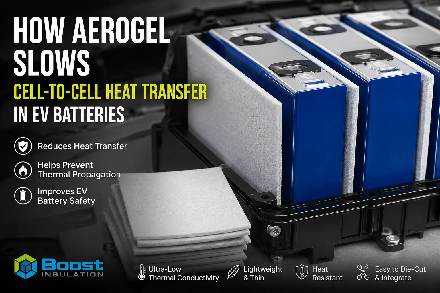
How Does Aerogel Slow Cell-to-Cell Heat Transfer in EVs?
Why Choose a China Factory for Die-Cut Insulation?
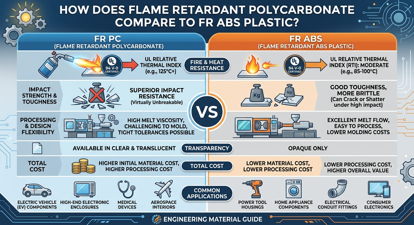
How Does Flame Retardant Polycarbonate Compare to FR ABS Plastic?
 betty wong