
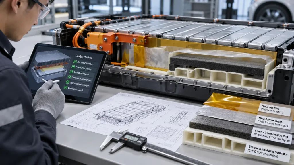
EV Battery Insulation Design Review Checklist for Engineers
An EV battery insulation design review should verify the assigned insulation function, electrical isolation architecture, thermal-event interfaces, mechanical fit, finished-part geometry, manufacturing controls, and validation evidence before design release. Engineers should link each requirement to a controlled drawing, measurable acceptance criterion, responsible owner, and test or inspection record. Unresolved safety-critical issues should block approval—not disappear into an open-action list.
This checklist is intended for battery module and pack design reviews at prototype, design-validation, production-validation, and manufacturing-release gates. It is deliberately different from a material-selection guide: choosing a PC film, mica sheet, aerogel barrier, or foam pad is only one input to a traceable engineering decision.
What Is an EV Battery Insulation Design Review?
An EV battery insulation design review is a documented cross-functional decision about whether a specific insulation architecture is fit for its defined use and ready for the next development gate. The review checks the complete installed part: material grade, geometry, electrical paths, interfaces, environment, assembly sequence, verification evidence, and production variation. It is not a datasheet comparison or a substitute for formal battery safety testing.
Use a simple requirement-to-evidence chain: requirement ID → hazard or failure mode → drawing or specification feature → verification method → result → accountable approver → disposition. A review is complete when every critical requirement has an accepted result or a formally controlled resolution. An issue can remain open for planning purposes; it cannot be silently treated as a pass.
Step 1 — Define Electrical, Thermal, and Mechanical Design Inputs
Freeze the design basis before debating film thickness. Identify the cell format and architecture, voltage and transient envelope, energized-to-chassis interfaces, environmental exposure, service life, swelling and vibration conditions, venting direction, thermal-event assumptions, installation sequence, and applicable OEM requirements. Assign each insulation location a unique part number and a primary function. If one part has multiple functions, verify each independently.
TABLE 1 | EV Battery Insulation Design Requirements Matrix
| Requirement | Failure risk | Review question | Required evidence |
| Voltage / fault envelope | Unintended shock or breakdown | Are local potentials, transients and fault states defined? | Approved electrical design basis; hazard analysis |
| Creepage / clearance | Surface tracking or air-gap failure | Are worst-case paths measured after assembly variation? | Dimensioned stack-up and path study |
| Thermal-event duty | Propagation or enclosure exposure | Is the barrier function and event scenario explicit? | Thermal hazard assessment; test plan |
| Mechanical envelope | Abrasion, puncture or interference | Are motion, swelling, vibration and fasteners bounded? | CAD sections; load and tolerance analysis |
| Environmental life | Loss of properties after aging | Are humidity, fluids, temperature and aging defined? | Exposure matrix; conditioned test results |
| Assembly / service | Missing, reversed or damaged part | Can the part be installed and inspected correctly? | Work instruction; poka-yoke / inspection plan |
| Change control | Unqualified material substitution | Is exact construction revision-controlled? | BOM, approved material list, ECN process |
For each row, distinguish a design target from an actual acceptance criterion. “High dielectric strength” is not measurable enough; “finished assembly passes the approved withstand test after specified conditioning” is a verifiable statement. Test voltages, durations, sampling, and environmental profiles must come from the governing program and validated methods—not a generic internet checklist.
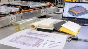
Step 2 — Review the Electrical Insulation Architecture
Trace every credible current path from energized conductors to adjacent conductors, cell cans, frames, fasteners, cooling hardware, and touch-accessible structures. Separate insulation through a solid barrier from clearance through air and creepage along surfaces. Examine holes, slots, exposed edges, burrs, compression points, contamination traps, and conductive debris. A higher dielectric-strength material cannot repair an unreviewed path around the material.
ISO 6469-3:2021 addresses electrical safety for specified voltage-class-B vehicle circuits; IEC 60664-1:2020+AMD1:2025 provides insulation-coordination principles within its stated scope. Neither should be converted into a universal battery-pack spacing rule without confirming the vehicle architecture, jurisdiction, applicable product requirements, and OEM design criteria.
TABLE 2 | Electrical Insulation Design Review Checklist
| Review item | Requirement to confirm | Verification method | Status / owner |
| Solid barrier | Approved grade, construction and minimum local thickness | Spec / drawing review; conditioned finished-part test | P / F / O — Electrical |
| Air clearance | Minimum path maintained at worst-case build | 3D CAD path analysis; physical fit study | P / F / O — Electrical |
| Surface creepage | Surface path includes slots, contamination and edges | Path measurement; environmental assessment | P / F / O — Electrical |
| Terminals / fasteners | No bypass, piercing or exposed metal contact | Section review; build inspection; fault analysis | P / F / O — Mechanical |
| Insulation resistance | Acceptance at defined test conditions | Approved assembly test procedure | P / F / O — Validation |
| Dielectric withstand | Finished construction survives required stress | Program-defined test, conditioning and records | P / F / O — Validation |
| Service / rework | Protection survives handling and authorized service | Process FMEA; work-instruction trial | P / F / O — Manufacturing |
P = Pass with traceable evidence; F = Fail against an approved criterion; O = Open issue requiring disposition. The matrix is a review template, not a list of preapproved test methods. Electrical design authority owns the pass/fail judgment; a converting supplier may supply dimensions and material records but should not be presumed to approve the vehicle-level safety architecture.
Step 3 — Separate Electrical Isolation from Thermal Protection
Thermal protection requires its own hazard statement. A film used to prevent busbar contact is not automatically a thermal-runaway barrier; a low-conductivity layer is not automatically a qualified dielectric. Map normal-operation heat flow, thermal propagation objectives, venting and gas pathways, and any expected high-temperature structural integrity. Use the correct material construction for the assigned function and verify it at the relevant component or system level.
TABLE 3 | Insulation Function and Material Matrix
| Function | Candidate construction | Important limitation | Validation focus |
| Thin electrical isolation | PC, PET or PI film | Grade, edges, aging and thickness govern outcome | Installed dielectric / mechanical evidence |
| High-temperature dielectric shield | Engineered mica laminate | Binder, reinforcement and edges affect behavior | Finished-part integrity and electrical tests |
| Thermal propagation barrier | Aerogel or engineered high-temp composite | Low conductivity alone does not prove event protection | Relevant thermal-event test configuration |
| Compression / vibration control | Silicone foam or tailored elastomer | Force relaxation and cell swelling change fit | Force–deflection and aged assembly behavior |
| Heat transfer to cooling system | Electrically insulating thermal interface material | Conductive heat path may oppose barrier objective | Thermal impedance and electrical isolation |
| Rigid support / mounting | Application-qualified FR4 or structural insulator | Hardware and edge paths can bypass bulk insulation | Mechanical and installed electrical review |
Treat UL 94 classifications as evidence of behavior in a specified small-scale material flammability test, not proof of pack-level thermal propagation performance. Verify the exact grade, test method, color or thickness conditions where relevant, and any adhesive or composite construction. Thin-film VTM classifications are not interchangeable with V classifications.
Regulation No. 100 for relevant vehicle approvals, or UL 2580 for battery assembly safety evaluation. Their scopes and legal or contractual applicability differ; none should be treated as a blanket certificate for an individual die-cut insulator.
For material-specific decisions, see Boost guides on PC insulation thickness, mica electrical insulation, and EV cell insulation pad selection. The present review addresses release evidence, not detailed grade selection.
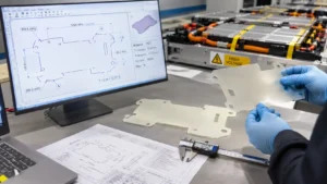
Step 4 — Review CAD, Installed Thickness, Tolerances, and DFM
A controlled 2D drawing should identify every safety-critical feature that the 3D model alone may hide: orientation, material side, adhesive location, liner removal, edge coverage, critical holes, datum scheme, minimum webs, burr-facing surfaces, and local thickness after forming or compression. Review tolerance accumulation at the worst-case assembled condition, not only at nominal CAD dimensions.
DFM approval is a design input. Tooling direction, cut quality, nesting, adhesive ooze, particulate generation, lamination registration, flatness, and part release can alter the delivered geometry. Request prototype parts made by the intended process when process-induced defects could affect the safety function.
TABLE 4 | CAD, Thickness, and Die-Cutting DFM Checklist
| Feature | Failure mode | DFM review action | Confirmation |
| Minimum local thickness | Puncture or electrical shortfall | Define post-process / post-compression minimum | Approved section / inspection |
| Cutouts and slots | Reduced edge cover or unintended path | Check location, radii, bridges and stack-up | Controlled 2D drawing |
| Fastener openings | Metal bypass or tear initiation | Review washers, torque, burrs and isolation | Assembly trial and drawing |
| Adhesive / liner | Creep, residue, poor bond or wrong orientation | Define full laminate stack and removal sequence | BOM, peel and fit evidence |
| Die-cut edge | Nicks, particles or exposed substrate | Agree edge criteria and inspection magnification | Limit samples / inspection plan |
| Flatness / handling | Misplacement or buckling | Review part size, support and automation | Prototype placement study |
| Datums / tolerances | Uncontrolled critical feature location | Set functional datums and capability plan | CTQ dimensions and gauge method |
Step 5 — Link Every Requirement to Validation Evidence
A validation plan must distinguish material screening, finished-part qualification, installed assembly performance, and battery-system assessment. A supplier datasheet can establish candidate suitability; it does not validate a cut edge, a laminated stack, a bent feature, or the final creepage path. Build an evidence matrix before prototype ordering so that each test has a defined specimen, conditioning, method, sample strategy, acceptance rule, and accountable reviewer.
Separate DV (does the design meet its requirements?) from PV (can the production-intent process repeatedly make conforming parts?). Where an OEM requires PPAP, connect the engineering drawing and CTQ characteristics to the control plan, process capability evidence, and production approval package. AIAG describes PPAP as a method for demonstrating consistent satisfaction of engineering design records and specifications under production conditions.
TABLE 5 | Engineering Validation Evidence Matrix
| Requirement ID | Evidence required | Accountable team | Acceptance criterion |
| E-01 Isolation | Assembly withstand and insulation-resistance reports | Electrical / validation | Approved procedure met after conditioning |
| E-02 Spacing | Worst-case CAD and as-built path measurements | Electrical / mechanical | Program minimums met in all defined states |
| T-01 Thermal event | Relevant component / pack event evidence | Thermal / safety | Program hazard objective demonstrated |
| M-01 Mechanical | Vibration, puncture / abrasion and compression results | Mechanical / validation | No functional loss under defined profile |
| A-01 Adhesive | Bond, aging and liner-removal validation | Materials / manufacturing | Approved retention and cleanliness limits |
| D-01 Dimensional | First-article inspection of CTQ features | Supplier quality | All critical dimensions conform |
| P-01 Process | Production-intent capability and control records | Manufacturing / SQE | Agreed capability and control criteria met |
| C-01 Configuration | Traceable grade, drawing and BOM revision | Program quality | No unresolved revision mismatch |
A test report is only useful if it identifies the exact configuration tested. Record part revision, material grade, thickness, adhesive construction, specimen orientation, conditioning, fixture, date, test method, and deviation history. When a component changes, assess whether previous evidence remains representative; do not automatically inherit approval from a superficially similar part.
Step 6 — Use Formal Design and Production Release Gates
A useful gate review distinguishes four decisions: Pass (evidence satisfies the requirement), Fail (evidence contradicts the criterion), Open (evidence is missing or incomplete), and Not Applicable (justified and approved). Define which issues are safety-critical hard stops. A deadline, prototype delivery, or supplier quotation is not evidence that an unresolved hazard has been controlled.
TABLE 6 | Design Release Gate Checklist
| Gate | Required deliverable | Disposition | Release decision |
| G0 — Requirements | Approved function map and design basis | P / F / O / N/A | No architecture release with undefined safety duty |
| G1 — Architecture | Electrical paths and thermal interfaces reviewed | P / F / O / N/A | No detailed-design approval with open critical hazard |
| G2 — DFM | Frozen CTQs, drawings and process feasibility | P / F / O / N/A | No tooling release with unresolved safety geometry |
| G3 — DV | Traceable tests on representative configuration | P / F / O / N/A | No DV sign-off on unverified critical requirement |
| G4 — PV / PPAP | Production-intent evidence and control plan | P / F / O / N/A | No serial release without required quality approval |
| G5 — Change | Approved ECN and revalidation assessment | P / F / O / N/A | No unassessed material or process substitution |
Record the decision, owner, date, document revision, open action, due date, and risk acceptance authority in the design review minutes. A conditional release may be permitted by the program governance for noncritical issues; it should never be represented as a general rule for electrical or thermal safety defects.

Ten Industry Insights That Change the Release Decision
INDUSTRY INSIGHT 1 | Material approval is not design approval
Engineering observation: A recognized polymer grade can still fail at a sharp busbar edge. Why it matters: Local geometry and installed stress may dominate the failure. Practical recommendation: Link the grade approval to the finished-part drawing and assembly test.
INDUSTRY INSIGHT 2 | Electrical isolation and thermal propagation are separate duties
Engineering observation: A thin dielectric film may have no demonstrated severe-heat barrier function. Why it matters: A single “insulation passed” status can conceal an unverified hazard. Practical recommendation: Assign separate requirement IDs and test evidence for each duty.
INDUSTRY INSIGHT 3 | Nominal thickness is not installed thickness
Engineering observation: Compression, forming and laminate tolerance change local build. Why it matters: A nominal gauge can overstate the available design margin. Practical recommendation: Specify the minimum functional thickness at the installed location.
INDUSTRY INSIGHT 4 | Die-cut geometry can become a safety risk
Engineering observation: A slot or fastener hole can shorten an electrical path. Why it matters: Small CAD changes may create large insulation consequences. Practical recommendation: Recheck creepage, clearance and edge coverage after each revision.
INDUSTRY INSIGHT 5 | A datasheet is not a validation plan
Engineering observation: Material coupons do not represent all finished-part interfaces. Why it matters: The team may approve properties that were never tested in situ. Practical recommendation: Create a specimen- and condition-specific evidence matrix.
INDUSTRY INSIGHT 6 | UL 94 is not battery-pack certification
Engineering observation: A V-0 or VTM rating describes a defined small-scale test. Why it matters: It cannot establish complete thermal propagation or electrical compliance. Practical recommendation: Review exact grade and thickness, then verify system requirements separately.
INDUSTRY INSIGHT 7 | Adhesives are functional layers
Engineering observation: Bond lines, liners and residues can change fit and contamination. Why it matters: A base-film certificate omits these construction effects. Practical recommendation: Qualify the complete laminate and define liner-removal controls.
INDUSTRY INSIGHT 8 | DFM belongs before design freeze
Engineering observation: A narrow bridge may be nominally drawable but unstable to convert. Why it matters: Late discovery creates tooling changes and validation resets. Practical recommendation: Request process-specific DFM and trial parts before the drawing is frozen.
INDUSTRY INSIGHT 9 | Evidence must remain traceable
Engineering observation: An unlabeled test report may refer to a superseded revision. Why it matters: Untraceable evidence weakens release and later change assessment. Practical recommendation: Connect requirement, drawing, test sample and approval identifiers.
INDUSTRY INSIGHT 10 | Release is a cross-functional decision
Engineering observation: Electrical, thermal, mechanical and quality teams own different risks. Why it matters: A supplier quote or single-function sign-off cannot close all hazards. Practical recommendation: Use named approvers and explicit hard-stop criteria at each gate.
Hypothetical Engineering Example: Busbar-to-Lid Insulation Release
Consider a hypothetical prismatic-cell module with an energized busbar close to a conductive pack-lid feature. The proposed solution is a die-cut flame-retardant polymer barrier with pressure-sensitive adhesive. This example is illustrative, not a customer project or a validated design. All dimensions, voltages and acceptance limits are intentionally left to the actual program design basis.
At G0, the team assigns E-01 to electrical isolation, E-02 to minimum installed spacing, M-01 to puncture and vibration exposure, and A-01 to adhesive retention. Thermal safety confirms that this polymer part is not credited as the pack’s thermal-propagation barrier; that function belongs to a separate reviewed architecture. The drawing identifies adhesive side, datum holes, critical edge coverage and the minimum installed barrier build.
At G1, the electrical reviewer finds a clearance path near a metal fastener that the nominal 3D view did not highlight. E-02 becomes Open. At G2, the converter identifies a narrow die-cut web and a liner-release problem. D-01 is Open until the cut geometry and handling method are revised. The team refuses tooling release, despite the candidate base film having an acceptable material datasheet.
After the CAD revision, prototype samples are produced to the intended process. The mechanical team verifies edge contact under worst-case assembly; electrical validation tests the finished installed construction after the specified conditioning; manufacturing verifies liner removal and placement; supplier quality checks CTQ dimensions against the new revision. The revised evidence package closes E-02 and D-01 only after recorded acceptance.
The final decision is Pass at the design gate if all safety-critical requirements are supported and signed off. PV remains Open until production-intent control-plan and capability evidence are accepted. This distinction prevents a successful prototype from being mistaken for an approved mass-production process.
Fifteen Common Design Review Mistakes—and Their Corrective Actions
- Treating a material certificate as pack approval. Risk: Installed edge or interface failure remains untested. Corrective action: Require finished-part and assembly evidence.
- Converting dielectric strength directly into a voltage-to-thickness rule. Risk: A misleading margin may hide the actual failure path. Corrective action: Apply approved insulation coordination and withstand criteria.
- Reviewing only nominal CAD clearance. Risk: Worst-case tolerance or aging can eliminate separation. Corrective action: Analyze and inspect defined worst-case states.
- Ignoring conductive fasteners and washers. Risk: Metal hardware can bypass the intended dielectric barrier. Corrective action: Review torque, burrs, interfaces and assembly fit.
- Assigning thermal propagation duty to a generic film. Risk: A thermal event may exceed the material’s demonstrated function. Corrective action: Require function-specific event evidence.
- Treating UL 94 V-0 as a pack certification. Risk: Small-scale flame behavior is mistaken for system safety. Corrective action: Separate material classification from pack qualification.
- Omitting adhesive from the controlled BOM. Risk: Unqualified bond lines or residues can alter performance. Corrective action: Control and test the full laminate construction.
- Freezing narrow webs without die-cut trials. Risk: Cut damage or release failures can affect placement. Corrective action: Validate representative process-made samples.
- Inspecting raw-sheet thickness only. Risk: Local formed or compressed sections may be thinner. Corrective action: Measure the minimum installed functional section.
- Accepting a report with no revision identification. Risk: Evidence may belong to an obsolete design. Corrective action: Trace test samples to grade, BOM and drawing revisions.
- Confusing design validation with production validation. Risk: A good prototype may mask an unstable process. Corrective action: Require separate DV and production-intent PV evidence.
- Testing before acceptance limits are approved. Risk: Results become difficult to interpret or dispute. Corrective action: Define method, conditioning and pass/fail criteria first.
- Closing open actions informally. Risk: A critical issue can disappear from the release record. Corrective action: Document authority, disposition and verification.
- Changing material grade without impact assessment. Risk: Prior testing may no longer represent the product. Corrective action: Use ECN review and targeted revalidation.
- Releasing tooling with an open safety-critical issue. Risk: Cost and schedule commitments may lock in a hazard. Corrective action: Enforce hard-stop release gates and re-review.
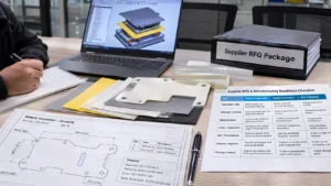
Prepare a Supplier RFQ and Manufacturing Readiness Package
A useful supplier review package is more than a PDF outline. Provide the application, insulation duty, controlled CAD and 2D drawings, material construction, critical-to-quality dimensions, inspection method, environmental assumptions, prototype quantity, expected annual volume, and requested evidence. State who owns the final electrical and thermal acceptance. Ask the supplier to identify manufacturability risks, process assumptions and any proposed deviation before quoting.
TABLE 7 | Supplier RFQ and Manufacturing Readiness Checklist
| Input | Customer responsibility | Supplier confirmation | Risk if missing |
| Application / duty | Identify location and functional safety role | Confirm scope and technical questions | Wrong construction quoted |
| Drawings / revisions | Issue controlled CAD, PDF and datum scheme | Confirm geometry and revision | Nonconforming fit or edges |
| Material stack | Define grade, thickness, adhesive and liner | Confirm sourcing and laminate build | Unapproved substitution |
| CTQs / inspection | Set tolerances, critical edges and gauge plan | Confirm inspection feasibility | Uncontrolled safety feature |
| DV / PV evidence | Define required tests and acceptance owners | Identify available supplier records | Evidence gap at release |
| Volume / logistics | Provide prototype and annual demand | Confirm process route and capacity plan | Scale-up or schedule risk |
| Change control | Define deviation and ECN approval process | Confirm traceability and notification | Silent design drift |
How Can Boost Insulation Support a Design Review?
Boost Insulation publicly describes engineering/DFM support, precision die cutting, CNC processing, and lamination for flame-retardant PC and aerogel insulation constructions. For a battery insulation project, a converting supplier can help identify manufacturability concerns in cutouts, narrow bridges, material yield, adhesive registration, prototype handling, and dimensional inspection. Those inputs are valuable before tooling and design freeze.
The battery OEM or designated engineering authority still owns the system-level safety case, required testing and release decision. Request a project-specific confirmation of material grades, available thicknesses, manufacturing capability, quality documents and testing scope rather than assuming that a general website claim applies to every part.
For an engineering discussion, submit the insulation function, electrical/thermal requirements, controlled drawings, material stack, minimum installed thickness, critical dimensions, adhesive construction, sample and annual quantities, and qualification needs through the Boost Insulation contact page.
Review relevant flame-retardant PC converting and aerogel insulation converting capabilities, then submit a technical inquiry with the controlled RFQ package.
Frequently Asked Questions
What should engineers check in an EV battery insulation design review?
Review the assigned insulation functions, electrical paths, thermal-event interfaces, mechanical loading, CAD geometry, manufacturing feasibility, and validation evidence. Each safety-critical requirement needs a defined acceptance criterion, controlled document revision, responsible owner, and recorded disposition. Open critical issues should prevent the relevant release gate from being approved.
How do you verify electrical insulation in an EV battery pack?
Start with the approved electrical design basis and trace solid-insulation, creepage, and clearance paths in the installed geometry. Verify worst-case tolerances, fasteners, edges, contamination, and environmental exposure. Then evaluate finished-part and assembly insulation-resistance or dielectric-withstand results using the program-approved methods, conditioning, and acceptance limits.
What is the difference between electrical insulation and thermal barriers in EV batteries?
Electrical insulation controls unintended current paths and electric-shock risks. Thermal barriers are intended to manage heat transfer or exposure during specified thermal events. A material may contribute to both, but neither duty should be assumed from a single property. Assign independent requirements and validate each at the appropriate level.
Why does insulation thickness matter in battery pack design?
Thickness affects physical separation, stiffness, puncture resistance, assembly fit, and sometimes thermal behavior. The important value is the minimum functional thickness after processing, tolerance variation, compression, and installation—not just nominal raw-sheet gauge. No universal thickness follows from battery voltage alone; the complete architecture and validation determine suitability.
How does die-cutting affect EV battery insulation performance?
Die cutting determines edge condition, cutout location, narrow-web integrity, dimensional repeatability, and sometimes particle generation. Holes and slots can alter creepage paths or expose metal edges. Engineers should review DFM before design freeze and qualify representative production-intent parts when cut quality can affect the insulation function.
What tests are required to validate EV battery insulation components?
The required tests depend on the component duty, applicable standard, OEM specification, and hazard analysis. A plan may include electrical withstand, insulation resistance, environmental aging, vibration, compression, adhesion, dimensional inspection, or thermal-event testing. Material, finished-part, assembly, and system evidence are not interchangeable; define acceptance criteria before testing.
What documents are needed before EV battery insulation design release?
Typical deliverables include an approved requirement matrix, hazard and interface analysis, controlled CAD and drawings, material/laminate specification, DFM disposition, validation plan and reports, critical-dimension inspection evidence, open-issue log, and cross-functional approvals. Production release may additionally require process controls, traceability, capability evidence, and customer-specified PPAP documentation.
How can a supplier support EV battery insulation DFM and validation?
A converting supplier can review cut geometry, tooling route, material construction, lamination, tolerances, inspection access, prototype handling, and production controls. It can provide samples and agreed manufacturing evidence. The OEM or authorized design owner must define safety acceptance criteria and determine whether component and system validation supports release.
Final Engineering Checklist and Next Steps
Before approving the next gate, confirm five outcomes: the insulation duty is unambiguous; every critical electrical, thermal and mechanical requirement has a traceable acceptance criterion; CAD and DFM risks are closed; representative validation evidence matches the released configuration; and production controls are defined for critical characteristics. If any safety-critical item is Fail or Open, assign an owner, corrective action, verification plan and formal re-review rather than treating schedule pressure as technical acceptance.
The practical objective is not to select the most impressive insulation material. It is to release a specific, manufacturable battery insulation design whose safety functions and evidence remain intact through production and controlled change.
Related Posts:
Are Flow Batteries a Better ESS Solution Than Lithium-Ion?
How Does Mica Insulation Compare With Polycarbonate?
What is UL94 V0? Guide to Flame Retardant PC Film Testing
What Insulation Does an Energy Storage System Need?

Why Use Rigid PC Insulation in EV Battery Modules?
How Does Mica Electrically Insulate EV Battery Packs?
 root