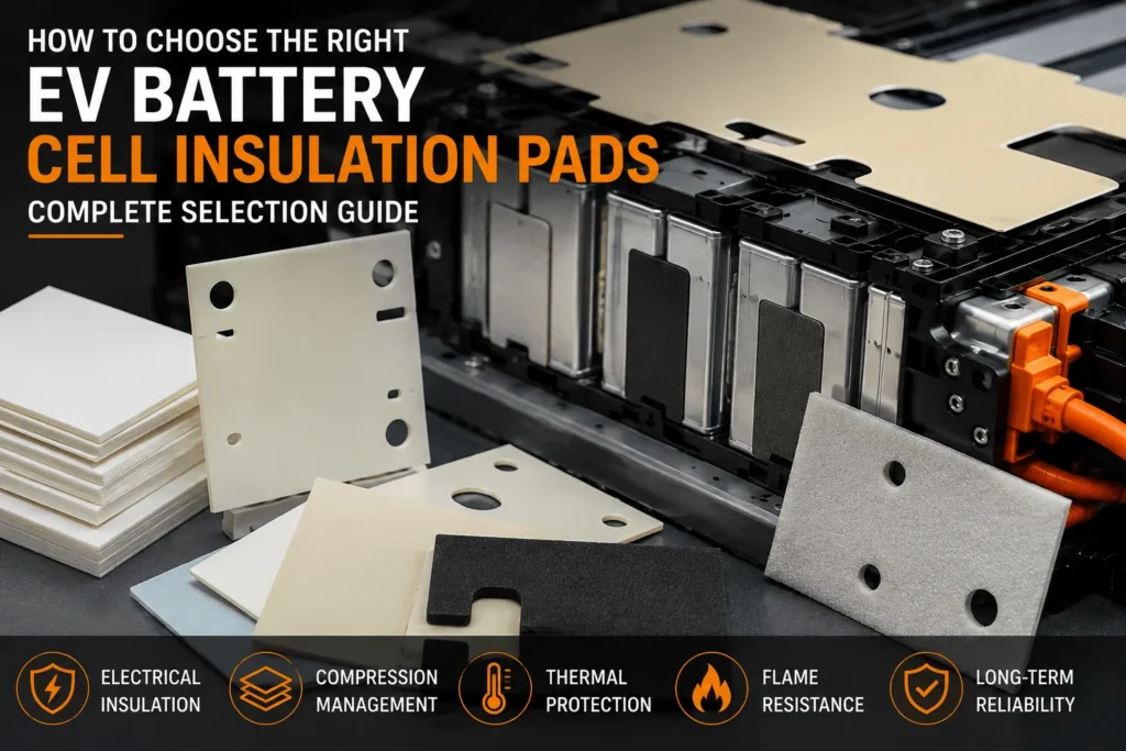
How to Choose EV Battery Cell Insulation Pads?
Table of Contents
Your cell drawing is frozen, the module envelope is tight, and the swelling allowance is already under pressure—but the insulation pad is still described only as “foam, 1.0 mm.” Is that specification detailed enough to protect dielectric clearance, control cell pressure, survive vibration, and support thermal-propagation targets throughout the battery’s service life? Usually not. An insulation pad may be one of the thinnest components in an EV battery module, yet choosing the wrong one can create some of the most expensive electrical, mechanical, and thermal failures.
To choose EV battery cell insulation pads, first define the pad’s primary function—electrical isolation, compression management, cushioning, heat transfer, or thermal-runaway protection. Then match the material to the cell format, operating voltage, compression-force window, temperature range, flame requirement, thickness tolerance, adhesive system, and module-level validation plan. The best pad is not the one with the highest single datasheet value; it is the one that maintains safe electrical and mechanical performance after aging, swelling, vibration, contamination, and repeated thermal cycling.
| Featured Snippet Target
Choose EV battery cell insulation pads by defining the required electrical, compression, thermal, and fire-safety functions first. Verify dielectric strength, force-deflection behavior, compression set, thickness, temperature resistance, flammability, adhesive compatibility, and die-cut tolerance under real module conditions—not only on a raw-material datasheet. |
Why EV Battery Cell Insulation Pad Selection Is a System Decision
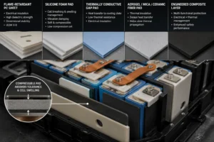
Battery engineers often use the term “insulation pad” for several very different components. A thin flame-retardant polycarbonate sheet may isolate a cell can, busbar, end plate, or side plate. A silicone foam pad may manage cell breathing and swelling while damping vibration. A thermally conductive gap pad may move heat from a cell or module into a cooling plate. An aerogel, mica, ceramic-fiber, or engineered composite layer may delay heat transfer during a thermal event. These products can overlap in function, but they are not interchangeable.
This distinction matters because optimization targets can conflict. A highly thermally conductive pad is useful when the design needs heat to reach a cooling plate, but it may be the wrong choice between adjacent cells when the objective is to slow thermal propagation. A very stiff sheet may offer excellent puncture resistance and dimensional stability, but it may concentrate stress on a pouch cell. A very soft foam may absorb tolerances, yet allow excessive cell movement or lose force after long-term compression. Selection therefore starts with the pack architecture and the failure modes—not with a material name.
Industry suppliers describe battery pads as components that must remain compressible enough to accommodate dimensional change while maintaining controlled force, alignment, vibration isolation, and long-term resistance to compression set and stress relaxation. This is especially important for pouch and prismatic cells that breathe during charge/discharge and may develop gradual permanent swelling over life [3–5].
Step 1: Define Exactly What the Pad Must Do
Before requesting samples, create a one-line functional statement for every pad location. A useful statement should identify the surfaces being separated, the electrical potential, the expected movement, the thermal direction, and the critical failure to prevent. For example: “Di-electrically isolate the aluminum cell can from the grounded side plate while absorbing 0.4 mm stack tolerance and maintaining a controlled compressive force from -40°C to 100°C.” That statement is far more actionable than “need battery foam.”
Five Common Functions
- Electrical isolation: prevent direct contact, leakage current, tracking, arcing, or breakdown between conductive parts at different potentials.
- Compression management: maintain an acceptable pressure window as cells breathe, swell, age, and experience production tolerances.
- Cushioning and vibration isolation: reduce local stress, fretting, impact damage, rattling, and cell movement.
- Thermal transfer: conduct heat toward a cold plate, heat spreader, or enclosure while maintaining electrical isolation.
- Thermal-runaway mitigation: slow heat and flame transfer from a failing cell to neighboring cells or structures.
Some designs need two or three of these functions from one die-cut part. Others achieve better reliability by separating functions into layers—for example, a rigid flame-retardant PC dielectric barrier plus a silicone foam compression layer, or a compression pad combined with a dedicated high-temperature barrier. A multi-layer construction can be easier to tune, but every lamination, adhesive, edge, and cutout becomes part of the qualification scope.
Step 2: Start With Cell Format and Module Architecture
Pouch Cells
Pouch cells have broad flexible faces and are sensitive to pressure distribution. The pad must accommodate reversible breathing and long-term swelling without creating pressure peaks that damage the pouch or reduce cell life. A relatively flat compression-force-deflection curve is often desirable because it helps keep force within a predictable range as the cell stack changes dimension. Low compression set and low stress relaxation are critical when the pack must retain pressure over thousands of cycles and years of exposure.
Prismatic Cells
Prismatic cells have more rigid housings but still change dimension with state of charge, temperature, and aging. Pads may be placed between cells, between cells and side plates, or at module end plates. Depending on the design, the priority may shift toward tolerance absorption, vibration isolation, electrical isolation of the metal can, or thermal propagation resistance. Large flat parts also require attention to bow, flatness, edge burrs, and positional accuracy during automated assembly.
Cylindrical Cells
Cylindrical architectures often rely on holders, spacers, sleeves, fishpole, flame-retardant films, potting materials, and localized pads rather than large face-compression cushions. The insulation design must address narrow gaps, vent directions, busbar proximity, and the large number of repeated features. Die-cut accuracy, clean release from liners, anti-static handling, and automated placement become major manufacturing factors.
Cell-to-pack and structural battery designs reduce the number of traditional module parts, but they do not eliminate insulation requirements. Instead, dielectric and thermal functions are pushed into fewer, larger, more integrated parts. This increases the value of early DFM review because a small geometry or tolerance change can influence material yield, assembly sequence, serviceability, and pack-level safety.
Step 3: Set the Electrical Insulation Requirements
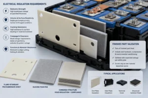
For a component called an insulation pad, electrical performance must be specified at the finished-part level. The raw sheet’s nominal dielectric strength is only the starting point. Actual performance can be affected by thickness variation, die-cut edges, holes, score lines, adhesive layers, contamination, humidity, compression, abrasion, and aging.
Key Electrical Properties
- Dielectric strength or breakdown voltage at the specified material thickness and test method.
- Volume and surface resistivity under dry, humid, hot, and aged conditions.
- Comparative tracking index or resistance to surface tracking when the application may see moisture or contamination.
- Creepage and clearance contribution based on the actual geometry, pollution environment, and system voltage.
- Resistance to puncture, edge cutting, fretting, and abrasion where sharp metal features or vibration are present
Do not convert a datasheet value in kV/mm directly into a design voltage without engineering margin. Thin materials do not always scale linearly, and local defects can dominate. The correct validation uses finished parts, representative electrodes or hardware, expected compression, environmental conditioning, and a test voltage defined by the OEM or Tier 1 safety plan.
Flame-retardant polycarbonate is often selected where a thin, dimensionally stable, puncture-resistant dielectric barrier is needed. It can be precision die-cut into large end-plate barriers, side-plate insulators, terminal covers, and structural isolation sheets. Silicone foam is selected when compliance, cushioning, sealing, or compression management is required. Combining the two can create a rigid electrical barrier with controlled compliance, but the laminate must be validated as a construction rather than assuming that each layer’s individual rating automatically applies to the final part.
Step 4: Choose the Correct Compression-Force Window
Compression pads are mechanical springs inside the battery stack. Their job is not simply to “fill a gap.” They generate force, and that force changes with deflection, temperature, time, cell swelling, manufacturing tolerance, and material aging. If the pad is too soft, cells may move, lose contact, rattle, or experience uneven support. If it is too stiff, assembly force may be excessive and the cell may be mechanically overloaded.
Evaluate the Full Force-Deflection Curve
Ask for compression force deflection (CFD) data across the full expected deflection range—not a single force value at one compression percentage. Model the minimum, nominal, and maximum stack conditions. Include cell thickness tolerance, pad thickness tolerance, frame tolerance, adhesive thickness, assembly compression, thermal expansion, reversible breathing, and permanent swelling. The design should remain inside the cell manufacturer’s allowable pressure window in all credible conditions.
Compression Set and Stress Relaxation Are Different
Compression set measures how much thickness is permanently lost after a material is compressed and released under specified conditions. Stress relaxation measures how much force decays while the material remains at a fixed compression. Both matter. A pad can recover much of its thickness after release yet still lose too much force during years of service. Conversely, a material may retain force but develop dimensional changes that compromise assembly. Rogers and Saint-Gobain both emphasize long-term compression behavior, controlled force, and accommodation of cell breathing/swelling in battery pad selection [3–5].
Temperature Changes the Force
Silicone foam is commonly considered when wide temperature capability, flame resistance, chemical stability, and compression-set resistance are important. Microcellular polyurethane may offer attractive force-deflection characteristics and density options, but the exact material family must be screened for temperature, humidity, flammability, and long-term aging. Never assume all “foam” behaves similarly. Cell structure, density, formulation, thickness, skin, adhesive, and compression history can materially change performance.
Step 5: Separate Thermal Insulation From Thermal Conductivity
One of the most common sourcing mistakes is asking for a “thermal pad” when the real need is a thermal barrier. These are opposite design directions. A thermally conductive pad reduces interface resistance and moves heat toward a cooling component. A thermal insulation pad reduces heat flow. A thermal-runaway barrier is designed to withstand a severe transient and delay heat, flame, or particle transfer. The same part may provide some dielectric insulation, but the thermal objective must be explicit.
Quick Function-to-Material Guide
| Primary function | Typical material direction | Key metrics | Main design risk |
| Rigid dielectric barrier | FR polycarbonate, PP/PI/PET film, engineered laminate | Breakdown voltage, puncture, flammability, thickness | Cracks, burrs, sharp-edge damage, insufficient creepage |
| Compression/tolerance pad | Silicone foam or microcellular polyurethane | CFD curve, compression set, stress relaxation, density | Too much or too little cell pressure over life |
| Heat transfer to cold plate | Thermally conductive dielectric gap pad | Thermal conductivity, bond-line thickness, dielectric strength | High assembly stress or unintended electrical path |
| Thermal propagation delay | Aerogel, mica, ceramic composite, engineered firewall pad | Heat-flux resistance, burn-through time, shrinkage, integrity | Using UL 94 alone as proof of runaway protection |
| Multifunction pad | Laminated PC + foam or engineered composite | All relevant electrical, mechanical and thermal data | Assuming individual layers equal final construction performance |
For normal heat removal, a thermally conductive gap pad should be evaluated by thermal impedance at the actual bond-line thickness, not by bulk conductivity alone. Contact resistance, surface flatness, compression, filler loading, and assembly force can dominate real performance. For propagation protection, evaluate the complete event: exposure temperature, heat flux, flame, hot particles, gas flow, vent direction, barrier compression, edge leakage, and the time needed to protect adjacent cells or occupants.
Step 6: Specify Flame Resistance Without Overclaiming It
UL 94 is widely used to classify how polymeric materials respond to a controlled ignition source. V-0, V-1, V-2, VTM, and 5V classifications address different specimen configurations and test conditions. UL states that these tests provide a preliminary indication of a polymeric material’s acceptability with respect to flammability for a particular application [1,2].
A UL 94 V-0 rating can be valuable for an EV battery insulation pad because it limits after flame and flaming drips under the specified test. However, it does not prove that a pad will block a cell thermal-runaway event, prevent pack propagation, or satisfy a vehicle regulation. Rating validity is tied to the exact material grade, color, thickness, and sometimes the specific construction listed in the certification record. Adding foam, PSA, liner residue, printing, coating, or another film can change the behavior.
| Engineering Rule
Treat UL 94 as one material-screening input. Treat thermal propagation as a system-level validation problem involving cells, spacing, vents, cooling, structures, barriers, sensors, and control strategy. |
Regulatory direction is increasing the emphasis on thermal-event management. UN Regulation No. 100 includes safety requirements for rechargeable electrical energy storage systems, while China’s GB 38031-2025 was published on March 28, 2025 and is scheduled to take effect on July 1, 2026 [7,8]. The trend is clear: suppliers are being asked for more evidence that insulation and barrier components continue to function in realistic, integrated battery constructions—not only in coupon tests.
Step 7: Match Temperature, Chemical, and Environmental Resistance
Define the normal operating range, storage range, short-term excursion temperature, and thermal-event exposure separately. A pad that performs well from -40°C to 100°C in normal operation may not remain dimensionally intact near a venting cell. Similarly, an excellent high-temperature barrier may be too brittle or abrasive for direct contact with a pouch surface during millions of vibration cycles.
Environmental Questions to Put in the Specification
- Will the pad contact electrolyte vapor, coolant, oil, cleaning agents, plasticizers, adhesives, or corrosion-inhibiting coatings?
- Can condensation or humidity reach the interface? Is the foam closed-cell, partially open-cell, or open-cell?
- Will the component see salt fog, dust, UV, ozone, or pressure washing at the pack or enclosure level?
- What are the outgassing, fogging, odor, ionic contamination, and volatile requirements?
- Must the material resist shrinkage, embrittlement, hydrolysis, or adhesive migration after aging?
Conditioned testing should reflect the actual risk. Common screening includes high-temperature aging, damp heat, thermal cycling, cold soak, chemical exposure, electrolyte surrogate exposure, flammability, dielectric testing after aging, compression set, stress relaxation, and vibration. The objective is not to run every available test; it is to connect tests to identified failure modes and acceptance criteria.
Step 8: Select Thickness From the Stack-Up, Not a Catalog
Pad thickness is a result of the dimensional stack and functional targets. For a compression pad, begin with the minimum and maximum available gap across all tolerances. Then select a free thickness that produces the required deflection range without bottoming out or losing contact. For a rigid electrical barrier, thickness is driven by dielectric margin, puncture resistance, rigidity, forming requirements, available space, and the minimum qualified flame rating.
A nominal 1.0 mm pad may arrive at a different measured thickness depending on the material standard, measurement pressure, release liner, skin, and lot tolerance. Foam thickness is especially sensitive to the measurement method. The drawing should specify whether thickness is measured before or after liner removal, the contact-foot pressure, conditioning time, and acceptable range. Without a common method, the supplier and customer may both measure correctly and still report different results.
Control Local Geometry
Slots, holes, narrow webs, sharp internal corners, embossed features, and thin bridges can change mechanical and electrical performance. A narrow die-cut web may stretch during liner removal. A sharp corner can initiate tearing. A hole located too close to a conductive edge may reduce creepage. A cutout can create a thermal bypass path during a cell event. DFM should review minimum web width, corner radius, edge-to-hole distance, kiss-cut depth, release direction, carrier design, and automated pick-and-place requirements.
Step 9: Decide Whether Adhesive Is Necessary
Pressure-sensitive adhesive can simplify assembly, prevent pad migration, and support automated placement. It can also create new risks: higher stiffness, lower recover ability, flame-rating changes, chemical interaction, liner contamination, difficult rework, or trapped air. Adhesive should be used because the assembly requires it—not because “backed with adhesive” sounds more complete.
Adhesive Selection Questions
- Which substrate will be bonded: aluminum, coated steel, cell pouch film, plastic frame, busbar coating, or another insulation layer?
- What are the surface energy, roughness, cleanliness, coating, and allowable primer conditions?
- Is the bond for temporary placement, permanent retention, sealing, or structural load?
- What peel, shear, creep, and reposition ability are required at minimum and maximum temperature?
- Does the final laminate retain the required flame, dielectric, aging, and chemical performance?
For cell-contact surfaces, confirm that the adhesive chemistry and residual monomers are acceptable to the cell manufacturer. For large die-cut parts, specify liner split, pull tab, finger lift, staged release, or carrier format to reduce assembly time and prevent wrinkles. A converter should be able to propose a liner and presentation method that fits the customer’s station, not merely supply loose pieces in a bag.
Step 10: Compare Material Families Against the Actual Use Case
| Material family | Best suited for | Strengths | Watch-outs | Typical die-cut form |
| Flame-retardant PC | Rigid cell/module dielectric barriers | Puncture resistance, stiffness, dimensional stability, formability | Not a compression pad; verify grade/thickness/UL record | Flat sheet, formed cover, end-plate or side-plate insulator |
| Silicone foam | Compression, cushioning, sealing, wide-temperature service | Resilience, temperature capability, compression-set resistance, flame options | CFD and stress relaxation vary widely by grade | Cell-face pads, end pads, strips, gaskets |
| Microcellular PU | Controlled compression and energy absorption | Tunable density/CFD, low mass, good cushioning | Check heat, humidity, hydrolysis, flame and aging limits | Compression pads and tolerance pads |
| Thermal gap pad | Heat transfer with electrical isolation | Conforms to surfaces, reduces interface resistance | Can impose assembly stress; not a thermal barrier | Cold-plate interface shapes |
| Aerogel/mica/composite | Thermal propagation delay and high-temperature isolation | Low heat transfer or high-temperature integrity | Brittleness, dust, handling, edge sealing, cost | Cell-to-cell barrier or firewall laminate |
The most robust answer is often a construction rather than a single commodity material. For example, a flame-retardant PC layer can create a clean, puncture-resistant dielectric surface, while a silicone foam layer absorbs tolerance and vibration. An engineered filled-silicone firewall pad may combine compression and thermal-propagation resistance [9,10]. The trade-off is that multi function parts demand more disciplined validation and change control.
Step 11: Design the Finished Die-Cut Part for Manufacturing
A battery insulation pad is purchased as a finished component, not as raw roll stock. Therefore, converter capability directly affects pack reliability. Precision die-cutting must control outer profile, hole position, narrow features, burrs, dust, part deformation, liner presentation, laminate registration, and lot traceability. For automated assembly, consistent pickup behavior can be as important as nominal dimensions.
DFM Items to Review Before Tooling
- Drawing datum strategy and critical-to-function dimensions.
- Tolerances that reflect real assembly needs rather than default tight values on every feature.
- Minimum radii, web widths, hole diameters, and spacing from edges.
- Material grain, foam cell direction, roll direction, skin orientation, and adhesive side.
- Part nesting and yield, including whether a small geometry change can reduce scrap.
- Flatness, bow, curl, release liner, pull tab, carrier pitch, packaging, cleanliness, and ESD handling.
- Inspection method: optical measurement, go/no-go gauge, thickness measurement pressure, visual defect limits, and sampling plan.
Boost Insulation positions its service around early DFM, in-house tooling, precision die-cutting, clean manufacturing, 48-hour custom samples, APQP/PPAP support, and lot traceability [11,12]. Those capabilities are most valuable when the supplier receives the real application conditions, not only a PDF outline. A good RFQ should include the cell format, material preference, thickness, compression range, voltage, temperature, fire requirement, adhesive side, annual volume, drawing format, and validation expectations.
Step 12: Validate the Finished Pad in Three Levels
Level 1: Raw Material Verification
- Material identity, grade, color, thickness, density, and certificate of analysis.
- Flammability classification at the relevant thickness and construction.
- Dielectric, thermal, mechanical, and environmental properties required by the design.
Level 2: Converted Part Verification
- Dimensions, hole position, burrs, flatness, laminate registration, liner release, adhesive coverage, and cleanliness.
- Breakdown voltage or insulation resistance on representative finished parts where required.
- Compression force deflection, compression set, stress relaxation, and aging on the selected thickness and laminate.
Level 3: Module and Pack Validation
- Assembly force and pressure distribution at minimum, nominal, and maximum tolerance.
- Vibration, mechanical shock, thermal cycling, humidity, coolant/electrolyte exposure, and service aging.
- Electrical isolation after environmental and mechanical testing.
- Thermal propagation, vent-gas routing, flame exposure, and adjacent-cell response where the pad is safety-relevant.
Coupon data is useful for screening, but it cannot reproduce every interface in a battery module. The final evidence must show that the selected pad works with the actual cell, enclosure, cooling system, adhesive, fasteners, preload, vents, and manufacturing process. This is also why uncontrolled material substitutions are dangerous—even when the replacement appears to have similar headline properties.
Step 13: Build a Supplier Approval Checklist
For global EV and energy-storage programs, the insulation-pad supplier should be evaluated as an automotive component manufacturer, not only a material reseller. The following questions identify whether the supplier can support development and stable production.
- Can the supplier provide the exact raw-material manufacturer, grade, UL file or certification evidence, thickness range, and lot traceability?
- Can engineering review the functional stack-up and propose material, thickness, adhesive, liner, and geometry improvements?
- Can the supplier produce representative prototypes quickly using the intended material and process?
- Are tooling, laminating, slitting, die-cutting, inspection, cleaning, and packaging controlled in-house or through qualified subcontractors?
- Can the supplier measure critical dimensions, thickness, dielectric withstand, compression behavior, flame response, and environmental aging as required?
- Does the quality system support APQP, PPAP, control plans, PFMEA, MSA, capability studies, change notification, and corrective action?
- Can packaging prevent curl, compression damage, liner contamination, mixed lots, and moisture uptake during international shipment?
- Can capacity, business continuity, raw-material allocation, and lead time support SOP and future volume growth?
Common Mistakes When Choosing EV Battery Cell Insulation Pads
Mistake 1: Choosing by Material Name Alone
“Silicone foam,” “PC sheet,” and “thermal pad” are product categories, not complete specifications. Different formulations within the same category can have dramatically different force, aging, dielectric, flame, and chemical behavior.
Mistake 2: Using the Highest Dielectric Strength as the Winner
Electrical safety depends on finished thickness, defects, geometry, creepage, environment, and aging. A material with a lower headline value but better puncture resistance, dimensional stability, and process control may produce the safer component.
Mistake 3: Ignoring Cell Pressure Over Life
A pad that fits during prototype assembly may generate excessive force after swelling or lose force after stress relaxation. Pressure must be modeled across the complete life and tolerance stack.
Mistake 4: Treating UL 94 V-0 as Thermal-Runaway Certification
V-0 is a useful flammability classification, but it is not a substitute for a cell, module, or pack propagation test. Severe battery events involve heat flux, flame, hot particles, gases, pressure, and long exposure periods beyond the UL 94 material test.
Mistake 5: Testing Raw Foam but Buying a Laminate
Adhesive, carrier film, coating, liner residue, printing, and lamination can change stiffness, flame behavior, dielectric properties, and aging. The approved construction should match the production part.
Mistake 6: Over-Tolerancing the Drawing
Unnecessarily tight tolerances increase tooling cost, inspection time, scrap, and supply risk. Tolerances should be linked to assembly and safety functions, with DFM used to identify dimensions that can be relaxed.
Mistake 7: Leaving Packaging Until SOP
Soft pads can be compressed in cartons; thin PC parts can curl; adhesive liners can lift; particles can migrate; and loose pieces can slow assembly. Packaging and presentation should be validated during the prototype phase.
A Practical Selection Matrix for Common Applications
| Application | Likely starting point | Critical questions | Typical validation | RFQ emphasis |
| Cell face compression | Silicone foam or microcellular PU | Pressure window, swelling, temperature, stress relaxation | CFD, set, relaxation, cycling, vibration | Cell pressure limits and gap stack |
| Metal can to side plate insulation | FR PC or film + optional foam | Voltage, sharp edges, puncture, movement | Dielectric after vibration/aging | Edge conditions and creepage |
| End-plate tolerance pad | Silicone foam or laminate | Maximum assembly force, long-term force retention | Stack compression and thermal cycling | Min/nom/max gap |
| Cold-plate interface | Thermally conductive dielectric pad | Thermal impedance, flatness, insertion stress | Thermal performance and dielectric withstand | Bond-line thickness and pressure |
| Cell-to-cell propagation barrier | Aerogel/mica/composite/firewall pad | Heat flux, vent path, spacing, compression | Module propagation event | Cell chemistry, trigger method, pass criteria |
Industry Insight: The Market Is Moving Toward Multifunction, Evidence-Backed Pads
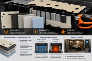
Three design shifts are changing how EV battery cell insulation pads are specified. First, higher energy density reduces the space available for separate insulation, cushioning, and fire-barrier layers. Engineers increasingly ask one thin component to perform multiple functions. Second, faster charging and higher-voltage architectures increase thermal and electrical stress, making small defects and interface resistance more important. Third, thermal-propagation regulations and OEM test methods are pushing validation from material coupons toward realistic cells, modules, and complete packs.
The commercial implication is significant: buyers will increasingly prefer converters that can translate pack requirements into a controlled material construction, produce prototypes quickly, and maintain traceability through SOP. A supplier that only quotes price per square meter cannot solve a compression, dielectric, and propagation problem. Conversely, a converter that can support DFM, testing, PPAP, and change control becomes part of the customer’s engineering risk-reduction process.
Another emerging trend is the separation of normal-operation thermal management from abuse-event protection. During everyday driving and charging, engineers want efficient heat removal and uniform temperature. During a cell failure, they may want to slow heat transfer to adjacent cells and route gases away from critical areas. The pad architecture must support both operating states without confusing a conductive gap filler with a protective barrier.
What Information Should You Send for a Fast, Accurate Quote?
A detailed RFQ reduces sample iterations and prevents the supplier from recommending a generic foam. Send as much of the following information as your confidentiality rules allow:
- 2D drawing and, where relevant, 3D assembly data; identify critical dimensions and datums.
- Cell format, chemistry, surface material, pad location, contact surfaces, and vent direction.
- Minimum, nominal, and maximum gap; required compression range and allowable force window.
- System voltage, dielectric withstand target, insulation resistance, creepage/clearance constraints, and sharp-edge conditions.
- Normal, storage, excursion, and event temperature requirements.
- Thermal objective: insulate, conduct, spread heat, or delay propagation.
- Flammability requirement, thickness-specific certification, and any OEM material standard.
- Adhesive side, substrate, liner format, automated assembly method, cleanliness, and packaging requirements.
- Prototype quantity, annual volume, SOP timing, PPAP level, validation plan, and required reports.
Why Work With Boost Insulation?
Boost Insulation is a China-based manufacturer focused on EV battery insulation, flame-retardant polycarbonate, silicone and thermal materials, and precision die-cut components. Its published capabilities include IATF 16949 and ISO 9001 quality systems, ±0.05 mm precision die-cutting, in-house tooling, clean manufacturing, DFM support, APQP/PPAP documentation, lot traceability, and rapid custom samples in as little as 48 hours [11,12].
For a new battery pad project, the practical value is a single development path from functional review to material selection, lamination, die-cutting, prototype validation, and volume production. Instead of sending separate RFQs to a foam distributor, film supplier, adhesive converter, and die cutter, customers can evaluate the finished component and its manufacturing controls as one supply package.
| Request a Technical Review
Upload your drawing, stack-up, cell format, target thickness, compression range, voltage, temperature, fire requirement, and annual volume. Boost Insulation can review the design, recommend a suitable PC, silicone foam, thermal, or composite construction, and prepare custom samples for verification. |
Frequently Asked Questions
What is the best material for EV battery cell insulation pads?
There is no universal best material. Flame-retardant polycarbonate is strong for rigid dielectric and puncture-resistant barriers. Silicone foam is strong for compression, cushioning, sealing, and wide-temperature performance. Thermally conductive pads are used for heat transfer, while aerogel, mica, ceramic, or engineered firewall materials are used when thermal-propagation delay is the main objective. Many modules use a laminate or multiple layers.
How thick should a battery cell insulation pad be?
Thickness should be calculated from the minimum and maximum gap, cell swelling, pad compression range, dielectric requirement, puncture risk, and manufacturing tolerance. Compression pads must generate acceptable force at every credible stack condition. Rigid barriers must meet electrical and mechanical requirements at the actual qualified thickness.
Are silicone foam pads electrically insulating?
Many silicone foams have good dielectric properties, but performance depends on formulation, density, thickness, fillers, cell structure, compression, temperature, humidity, and aging. Use the exact grade’s data and validate the finished die-cut pad in the actual construction.
Does UL94 V-0 mean a pad prevents thermal runaway?
No. UL94 V-0 describes material response in a specified small-flame test. It does not certify that the pad will stop thermal runaway or propagation in a battery pack. Propagation protection requires module- or pack-level testing under the relevant cell and architecture conditions.
Should battery insulation pads have adhesive backing?
Adhesive is useful when it improves placement accuracy, prevents movement, or supports automation. It should be avoided when it adds excessive stiffness, creates chemical risk, changes flame behavior, complicates rework, or is unnecessary after mechanical compression. Validate the final laminate, not only the base pad.
What tolerance can a die-cut battery insulation pad achieve?
Tolerance depends on material thickness, softness, geometry, tool type, part size, liner, and inspection method. Rigid films and sheets can usually hold tighter dimensions than soft foams. Critical tolerances should be reviewed during DFM so the process is capable without unnecessary cost or scrap.
How can I compare two battery pad suppliers?
Compare the exact material source, thickness-specific certifications, force-deflection and aging data, finished-part inspection capability, DFM support, prototype speed, APQP/PPAP readiness, lot traceability, change control, packaging, and capacity. Do not compare only price and nominal thickness.
Conclusion
Choosing EV battery cell insulation pads requires more than selecting a material with a high dielectric value or a V-0 rating. The correct pad must perform a defined job inside a defined cell and module architecture. It must maintain electrical isolation, pressure, geometry, and thermal behavior after realistic compression, swelling, vibration, temperature cycling, contamination, and aging.
Start by defining the pad’s primary and secondary functions. Build the dimensional and pressure stack. Separate heat-transfer needs from thermal-barrier needs. Validate the exact material grade, thickness, adhesive, and die-cut construction. Then qualify the finished component at raw-material, converted-part, and module levels. This process turns a thin pad from a commodity into a controlled safety component—and gives procurement teams a defensible basis for choosing a long-term supplier.
For a material recommendation or custom die-cut sample, send Boost Insulation your drawing and application requirements. A technically complete RFQ will produce a faster quote, fewer prototype rounds, and a more reliable path to mass production.
Technical References and Further Reading
- UL Solutions – Combustion (Fire) Tests for Plastics: https://www.ul.com/services/combustion-fire-tests-plastics
- UL Standards & Engagement – UL 94 Scope: https://www.shopulstandards.com/ProductDetail.aspx?productId=UL94_7_S_20230228
- Rogers Corporation – Battery Pads & Cushions: https://www.rogerscorp.com/Applications/Battery%20Pad%20and%20Cushion
- Saint-Gobain – EV Battery Cell Swelling and Compression Pads: https://www.tapesolutions.saint-gobain.com/en-gb/node/8196
- Rogers Corporation – PORON EVExtend Battery Pad Material: https://www.rogerscorp.com/Elastomeric%20Material%20Solutions/PORON%20Industrial%20Polyurethanes/PORON%20EVExtend
- Saint-Gobain – Battery Thermal Runaway Propagation Mitigation: https://www.tapesolutions.saint-gobain.com/en-gb/technical-articles/material-solutions-battery-pack-thermal-runaway-propagation-mitigation
- UNECE – UN Regulation No. 100, Revision 3: https://unece.org/sites/default/files/2024-01/R0100r3e.pdf
- AMR – GB 38031-2025 Official Standard Record: https://openstd.samr.gov.cn/bzgk/std/newGbInfo?hcno=3AB693FAFF5D9716DF61C61D6FD2187A
- Rogers Corporation – ProCell EV Firewall PCL-350: https://rogerscorp.com/elastomeric-material-solutions/procell-ev-firewall/procell-ev-firewall-pcl-350
- Boost Insulation – EV Battery Insulation & Precision Die-Cutting: https://boostinsulation.com/
- Boost Insulation – Quality and Reliability FAQ: https://boostinsulation.com/faqs/how-do-you-ensure-the-reliability-and-quality-of-your-products/
- Boost Insulation – Rapid Custom Samples FAQ: https://boostinsulation.com/faqs/what-are-the-main-industries-and-applications-that-sinoextrud-caters-to/ plans
Editorial note: Technical values and acceptance criteria must be confirmed against the customer drawing, cell supplier limits, exact material grade, current certification records, and applicable OEM/regulatory test before publication or use in a safety decision.
Related Posts:
How Can You Prevent UV Yellowing in FR Polycarbonate?
How Does Flame Retardant Polycarbonate Compare to FR ABS Plastic?
How Does Aerogel Handle Cell Venting Heat in EV Packs?
What Insulation Does an Energy Storage System Need?
How Does Battery Aerogel Insulation Work in EV Packs?
Where Should Thermal Barriers Be Placed Between Cells?
 betty wong