How Do Cell-to-Cell Barriers Prevent Thermal Runaway?
Table of Contents
What happens in the few seconds after one EV battery cell enters thermal runaway? If the heat, flame, and pressure reach the next cell before the module can dissipate them, a local defect can become a pack-wide emergency. That is why the thin barrier between neighboring cells is not packaging filler—it is a critical part of the battery’s propagation-control strategy.
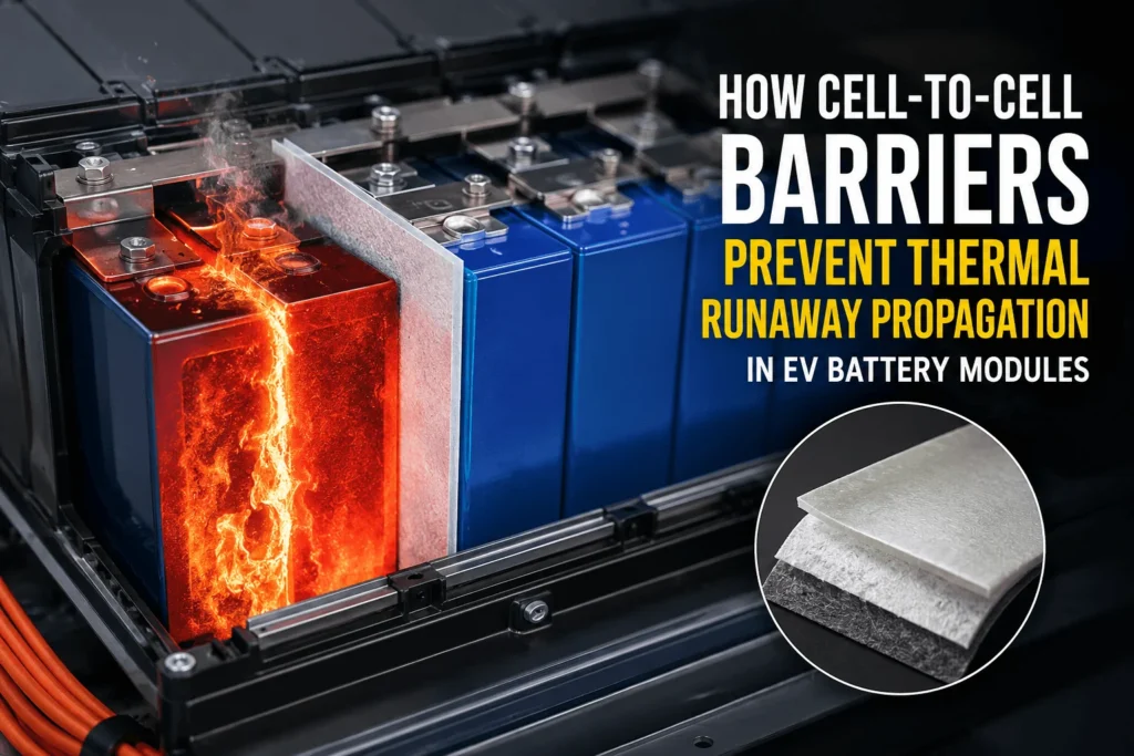
| Cell-to-cell barriers prevent thermal runaway propagation by slowing heat transfer from a failing cell, absorbing part of the heat pulse, blocking flame and hot particles, and preserving electrical and physical separation. When the barrier keeps adjacent cells below their critical self-heating temperature long enough for heat to dissipate, the failure remains localized instead of becoming a module-wide chain reaction. |
The Critical Distinction: Preventing Thermal Runaway vs. Preventing Propagation
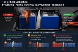
A cell-to-cell barrier normally cannot stop the initiating cell from entering thermal runaway after a severe internal short circuit, crush event, overcharge, manufacturing defect, or other abuse condition has already crossed the cell’s stability limit. The more accurate engineering objective is to prevent or delay thermal runaway propagation—the transfer of enough energy from the failed cell to trigger a neighboring cell.
This distinction matters for specifications and marketing claims. A low-conductivity sheet may be described as a “thermal runaway barrier”, but its actual job is to control the heat-transfer paths and hazards around the failed cell. Its success must be demonstrated in the intended cell format, state of charge, module geometry, compression condition, vent direction, cooling architecture, and trigger method. A material certificate by itself does not prove module-level propagation resistance.
For battery designers, the target outcome can be one of three levels: complete non-propagation, a meaningful delay that enables warning and occupant egress, or controlled propagation that prevents hazardous flames, smoke, and structural failure outside the enclosure. The correct target depends on the vehicle platform, market, applicable regulation, and the OEM’s internal safety requirements.
How Does Thermal Runaway Move from One Cell to the Next?
Thermal runaway propagation is not a single-mode heat-transfer problem. A barrier may perform well against one pathway and fail because another pathway bypasses it. Effective module design therefore starts by mapping how energy leaves the trigger cell and how it can reach adjacent cells.
Direct conduction through cell faces is often the dominant path in tightly packed prismatic and pouch modules. The failed cell surface heats the barrier, and energy then crosses the barrier into the neighboring cell. Busbars, tabs, end plates, cooling plates, frames, fasteners, and other solid components can create parallel conduction paths around the nominal cell-to-cell barrier.
Thermal radiation becomes important as surfaces, flames, and ejected particles reach very high temperatures. A low thermal conductivity value does not automatically mean strong radiant-heat protection. Surface emissivity, reflective facings, charring behavior, barrier opacity, and gap geometry can materially change the radiative load on the next cell.
Hot gases, flame jets, electrolyte droplets, and incandescent particles can transport energy much faster than slow conduction through a flat sheet. If the barrier has open edge gaps, terminal cutouts, misaligned vent windows, torn corners, or delaminated facings, the ejects can bypass the protected face and directly attack the neighboring cell or polymer components.
Mechanical and electrical changes also accelerate propagation. A pouch cell may swell and redistribute pressure. A prismatic can may bulge. A cylindrical cell can vent axially. These movements can close intended air gaps, compress a soft barrier beyond its design range, damage an insulating film, or bring conductive components into contact. The barrier therefore needs to survive the event mechanically as well as thermally.
How Cell-to-Cell Barriers Break the Propagation Chain
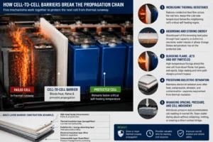
A successful barrier does not rely on one property. It combines several mechanisms so that the neighboring cell receives less energy, receives it more slowly, or remains protected from the most aggressive heat and flame pathways.
- Increasing thermal resistance — The barrier reduces conductive heat flow across the cell face. In simplified steady-state terms, thermal resistance increases with thickness and decreases with thermal conductivity. Real thermal runaway is transient, however, so engineers must also consider density, specific heat, thermal diffusivity, compression, and temperature-dependent properties. The practical goal is to keep the cold-side temperature below the neighboring cell’s critical self-heating region during the most severe part of the event.
- Absorbing and storing energy — Materials with useful heat capacity, endothermic reactions, water release, or phase-change behavior can absorb part of the incoming pulse. This can flatten the cold-side temperature curve and extend the time before a neighbor approaches its onset condition. The mechanism must be evaluated at the actual heating rate; a slow furnace test may not represent a cell that releases most of its heat in seconds.
- Blocking flame, jets, and hot particles — High-temperature facings, mica layers, ceramic papers, metal foils, glass fabrics, and engineered firewall coatings can shield the neighboring cell from direct flame impingement and ejects. Edge sealing and vent-path design are essential because hot material will follow the easiest opening. A barrier that protects only the broad cell face may still fail at tabs, corners, or vent exits.
- Preserving dielectric separation — The event can deform metal cans, tabs, busbars, and module frames. A barrier or laminated stack may need to maintain electrical isolation after heat exposure, abrasion, compression, and contamination. This is a different requirement from thermal insulation, which is why many modules use a multi-layer construction rather than asking one material to provide every function.
- Managing spacing, pressure, and cell movement — In pouch modules, a compressible pad can distribute pressure and accommodate cycling-related swelling during normal life. During abuse, it must not collapse, melt, or create a direct contact bridge. The best solution may combine a compressible layer for lifetime mechanics with a high-temperature firewall layer for abuse tolerance.
Why Time Is the Real Design Currency
Thermal propagation control is fundamentally a race between heat input and heat removal. If the neighboring cell absorbs heat faster than the module can spread, vent, or reject it, its internal reactions accelerate. If the barrier delays the heat pulse long enough, energy can be redistributed into the cold plate, frame, enclosure, neighboring non-triggered components, or ambient environment without pushing the next cell past its runaway threshold.
This is why “delay” is valuable even when a design objective is not full non-propagation. Extra seconds or minutes can support earlier detection, electrical isolation, occupant warning, controlled venting, emergency response, and lower peak heat-release rate. UN Regulation No. 100 includes a thermal-propagation safety approach linked to advance warning and occupant egress, while current U.S.
rulemaking proposals emphasize documented risk mitigation for single-cell thermal runaway and propagation. China’s GB 38031-2025, effective July 1, 2026, further signals a market shift toward more demanding system-level thermal safety.
An NREL-led pouch-cell study illustrates why transient performance matters. Basic polyurethane pads delayed propagation compared with no pad, but more robust multilayer firewall and intumescent constructions were required to fully stop cascading failure in the tested configuration. The same study recorded very rapid temperature rise and barrier-interface temperatures of several hundred degrees Celsius. The lesson is not that one named material always works; it is that architecture, thermal stability, coating integrity, and heat-transfer rate must be engineered together.
Which Materials Are Used for Cell-to-Cell Thermal Barriers?
There is no universal “best cell-to-cell barrier”. Material selection depends on cell chemistry, capacity, form factor, spacing, compression, vent direction, allowable thickness, mass target, dielectric requirement, production process, cost, and validation method. The most reliable designs often use a hybrid stack in which each layer has a defined function.
| Material family | Primary contribution | Main advantages | Design cautions | Typical role |
| Silica aerogel sheets/felts | Very low heat transfer through thickness | Thin, lightweight, strong transient insulation potential | Fragile edges, dust control, compression and facing behavior must be managed | Core insulation layer between large-format cells |
| Mica sheets/papers | High-temperature firewall and dielectric separation | Heat resistance, dimensional integrity, electrical insulation | Higher stiffness and possible brittleness; conductivity may be higher than aerogel | Hot-side shield, dielectric firewall, cover or edge protection |
| Ceramic/fiber papers | High-temperature resistance and flame shielding | Low mass, conformability, wide temperature capability | Fiber shedding, moisture, handling and compression sensitivity | Firewall facing or gap insulation |
| Engineered compressible foams | Pressure control, cushioning, spacing | Supports pouch-cell swelling and assembly tolerance | Base polymer may decompose unless specially engineered for abuse | Mechanical pad combined with high-temperature layers |
| Intumescent/endothermic composites | Energy absorption and protective char formation | Can delay heat penetration and shield flame | Activation rate, expansion space, residue and aging must be validated | Reactive layer in a multi layer barrier |
| Phase-change materials | Latent heat absorption and temperature buffering | Absorbs a defined amount of energy near transition range | Saturation, leakage/encapsulation, mass and long-term stability | Supplementary energy-absorption layer |
| Flame-retardant PC/PI/PET films | Dielectric isolation and clean assembly surface | Thin, precise, easy to die-cut and laminate | Limited thermal insulation alone; temperature rating and thickness matter | Electrical layer, carrier, surface protection |
| Metal/graphite heat spreaders | Redirects heat laterally to heat sinks or enclosure | High in-plane heat spreading | Can conduct heat toward other cells and requires dielectric isolation | System-level heat-path control, not standalone insulation |
Why Room-Temperature Thermal Conductivity Is Not Enough
A supplier datasheet may highlight a very low thermal conductivity measured near room temperature. That number is useful, but it cannot predict thermal runaway performance by itself. Battery barriers experience high heating rates, steep temperature gradients, compression, flame, reactive gases, particles, and possible structural movement.
The properties that matter include thermal conductivity through thickness, volumetric heat capacity, thermal diffusivity, shrinkage, decomposition temperature, mass loss, char formation, flame resistance, gas generation, dielectric strength after aging, compression set, puncture resistance, edge durability, and adhesive stability. Some barriers become more protective as they form a char or expand; others lose thickness, crack, shrink, or delaminate exactly when protection is most needed.
The cold-side temperature curve is usually more informative than a single conductivity value. Engineers should ask how long the barrier maintains a safe cold-side temperature under a representative heat flux, whether the barrier remains intact after the test, and whether heat or flame bypasses through cutouts and edges.
Cell Format Changes the Barrier Design
Prismatic cells usually present large, flat heat-transfer areas and relatively short cell-to-cell distances. Barriers may need high coverage, controlled thickness, robust edge geometry, and compatibility with cell swelling and can deformation. Terminal and vent regions require special attention because a full-face sheet can still be bypassed by hot gases or conductive hardware.
Pouch cells require pressure management throughout cycle life. A cell pad may need to maintain a defined compression window while preventing local pressure peaks. The abuse layer must remain effective when the pouch expands rapidly and the module stack load changes. Soft foam alone may provide excellent normal-operation mechanics but insufficient high-temperature stability; a hybrid compressible-firewall construction can separate these functions.
Cylindrical modules introduce curved contact, discrete spacing, cell holders, and directional venting. Interstitial barriers, sleeves, rings, spacers, and top-side shields may be more relevant than a simple flat sheet. Propagation can travel through holders and busbar regions, so the barrier concept must match the actual vent and conduction paths.
Cell-to-pack and module less architectures increase the importance of integrated protection. Removing structural parts can improve energy density but can also reduce natural separation and thermal mass. The barrier may need to serve several roles at once: propagation control, dielectric insulation, tolerance compensation, assembly aid, and structural protection. This makes design-for-manufacturing input earlier in the program more valuable.
Eight Design Factors That Decide Whether a Barrier Works
- Full-area coverage and edge protection A barrier should cover the heat-transfer area that the module actually exposes. Partial coverage can delay propagation yet leave a high-flux path through uncovered regions. Corners, tabs, vents, frame interfaces, and adhesive-free edges require explicit review.
- Thickness after assembly Nominal thickness is not the same as installed thickness. Compression, lamination pressure, adhesive flow, and tolerance stack-up change the final heat path. Specify thickness under the relevant load, not only free-state caliper.
- Temperature-dependent material behavior Request data beyond ambient conditions. A barrier can have excellent room-temperature insulation and still shrink, oxidize, melt, or lose cohesion at abuse temperatures.
- Compression and recovery For pouch cells, define compression force, stress relaxation, compression set, and recovery across temperature and aging. Excessive stiffness can create pressure hot spots; excessive softness can allow movement or collapse.
- Adhesive and lamination integrity The adhesive can be the weakest layer. It must survive thermal cycling, electrolyte exposure risk, humidity, vibration, and high-temperature excursions without edge lift, residue migration, or conductive contamination.
- Dielectric performance in the real part Evaluate withstand voltage, insulation resistance, creepage, clearance, burr risk, and post-aging performance on the finished die-cut component—not only on pristine raw material.
- Vent and ejecta management Determine where gases and particles will travel. A barrier should support a controlled vent route rather than unintentionally trap pressure or redirect flame toward a weaker component.
- Manufacturing repeatability Propagation performance depends on consistent geometry. Burrs, tears, dust, misregistration, liner fragments, wrinkles, uneven lamination, and thickness drift can create weak points that are invisible in a raw-material certificate.
Why Precision Die-Cutting Matters to Thermal Safety
Cell-to-cell barriers are often thin, complex, and installed in highly constrained assemblies. A drawing may include small terminal windows, vent reliefs, locating holes, fold lines, adhesive zones, release-liner tabs, and tight edge clearances. Each feature can affect thermal, electrical, and assembly performance.
A gap that is only a few millimeters wide can become a direct jet path. A misregistered multi layer laminate can expose a low-temperature foam at the hottest edge. A rough cut can damage a pouch film or create debris near high-voltage components. Excess adhesive squeeze-out can contaminate a dielectric surface. Poor liner design can slow assembly and cause operators to touch or distort fragile aerogel parts.
For this reason, the converter should be involved before the drawing is frozen. A design-for-manufacturing review can simplify geometry, define realistic tolerances, improve nesting and yield, select a suitable cutting process, add handling tabs, control fragile edges, and create an inspection plan that verifies the features most relevant to safety. The lowest material price per square meter is not the lowest program cost if scrap, assembly defects, or repeated propagation tests delay validation.
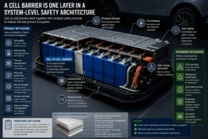
A Cell Barrier Is One Layer in a System-Level Safety Architecture
A cell-to-cell barrier should never be treated as the only safety control. Thermal propagation is influenced by cell quality, chemistry, state of charge, module electrical topology, current interruption, fusing, busbar design, sensing, cooling, vent routing, enclosure strength, fire shielding, and software diagnostics.
Primary mitigation aims to reduce the probability of cell failure and prevent propagation. Examples include manufacturing quality control, cell spacing, heat sinks, coolant design, electrical protection, and predictive battery-management functions. Secondary mitigation reduces consequences through warnings, emergency notification, controlled venting, enclosure protection, and occupant separation. Current regulatory discussions increasingly expect manufacturers to document how these controls interact rather than relying on a single pass/fail material property.
The engineering implication is clear: specify the barrier from a system requirement, not from a catalog description. Define what energy it must manage, for how long, at what compression, and with which bypass paths. Then validate the complete assembly.
How Should Cell-to-Cell Barriers Be Tested?
A sensible validation plan progresses from material screening to component testing and then module- or pack-level abuse testing. Each stage answers a different question.
- Material characterization Measure through-thickness thermal properties over the relevant temperature range, heat capacity or endothermic behavior, mass loss, shrinkage, flammability, dielectric strength, compression, puncture resistance, and aging behavior.
- Finished-part inspection Verify dimensions, thickness, layer registration, adhesive pattern, edge condition, cleanliness, peel strength, liner removal, and dielectric performance of the actual die-cut laminate.
- Bench heat-shield testing Expose the hot side to representative heat flux, temperature, duration, pressure, and gas flow. Record cold-side temperature and inspect the part for burn-through, shrinkage, delamination, cracks, and edge bypass.
- Two-cell or submodule testing Evaluate the actual cell-to-cell interface under realistic spacing, compression, SOC, trigger method, vent orientation, and cooling boundary conditions. Two-cell tests are useful for screening but may not reproduce the thermal mass and heat paths of a larger module.
- Representative module and pack validation Confirm the complete safety concept, including barriers, cooling plate, busbars, vents, sensors, enclosure, warning logic, and assembly tolerances. Use the applicable regulatory and customer procedures and repeat enough tests to understand variability.
Industry Insight: Five Common Specification Mistakes
- Specifying only “lowest thermal conductivity.” This ignores heat capacity, stability, compression, flame shielding, edge bypass, and temperature dependence.
- Using UL 94 V-0 as proof of propaatigon protection. A flammability classification is useful for material burning behavior at a stated thickness, but it is not a thermal runaway propagation test.
- Approving raw material but not the laminate. Adhesive, carrier film, foil, coating, ink, liner residue, and cutting damage can change the finished part’s behavior.
- Copying thickness from another battery program. Different cells release different energy and vent in different directions. The same thickness can perform very differently in another module.
- Waiting until DV testing to involve the converter. Late manufacturability changes can alter coverage, compression, adhesive zones, and tooling, forcing expensive retesting.
What Information Should You Send for an Accurate Cell-Barrier Quote?
A qualified supplier can respond faster and recommend a more appropriate construction when the inquiry includes engineering context. The following information turns a generic price request into a manufacturable thermal-safety project:
- 2D drawing and, where available, 3D module data.
- cell format, chemistry, capacity, dimensions, and maximum validation state of charge.
- cell-to-cell gap, installed compression, stack force, and expected swelling range.
- required function: thermal propagation barrier, dielectric insulation, cushioning, flame shield, or multi-function stack.
- target thickness and allowable tolerance after assembly.
- available heat-flux, cold-side temperature, or propagation-test requirements.
- dielectric withstand voltage, insulation resistance, flammability, environmental, and cleanliness requirements.
- adhesive type, adhesive-free zones, liner style, tab design, and assembly method.
- prototype quantity, validation schedule, annual volume, packaging, traceability, and PPAP expectations.
How Boost Insulation Supports Cell-to-Cell Barrier Development
Boost Insulation combines material conversion with precision die-cutting for EV battery module insulation. Our published capabilities include engineered aerogel and mica solutions, flame-retardant dielectric films, thermal pads and gels, multi layer lamination, clean-room-controlled manufacturing, DFM review, and rapid prototypes for fit and validation.
For cell-to-cell barrier projects, our engineering process focuses on the details that connect material performance to module performance: installed thickness, coverage, vent and terminal geometry, compression, adhesive zones, edge integrity, handling, and production repeatability. We can convert customer-nominated materials or help screen a practical multi layer construction based on the drawing and performance targets.
The best time to review a barrier is before design freeze. Early samples allow the battery team to check fit, pressure distribution, assembly sequence, dielectric protection, and thermal test behavior while geometry can still be optimized. This reduces the risk that a late tooling or material change triggers another round of costly module validation.
Frequently Asked Questions
Do cell-to-cell barriers stop thermal runaway inside the failed cell?
Usually no. They are designed mainly to prevent or delay propagation from the failed cell to neighboring cells. Prevention of the initiating event depends on cell design, manufacturing quality, BMS controls, electrical protection, thermal management, and mechanical protection.
Can an aerogel sheet prevent thermal runaway propagation?
It can be a highly effective low-conductivity layer, but performance depends on grade, thickness, compression, facing, edge coverage, cell energy, venting, and the rest of the module. It must be tested in the intended assembly.
Is mica better than aerogel for battery barriers?
Neither is universally better. Mica offers high-temperature integrity and strong dielectric/fire-shield behavior; aerogel offers very low thermal conductivity at low mass and thickness. Many designs combine them or pair either material with foam, film, foil, or adhesive layers.
How thick should a cell-to-cell barrier be?
There is no universal thickness. It must be derived from the cell’s heat release, available gap, allowable cold-side temperature, compression, heat-removal paths, barrier properties, and validation target. Thickness should be specified in the installed condition.
Why can a barrier pass a material test but fail in a module?
Module failure can result from edge gaps, vent jets, busbar conduction, compression, delamination, adhesive degradation, geometry variation, or a trigger condition that is more severe than the screening test.
Does UL 94 V-0 mean the barrier will stop propagation?
No. UL 94 V-0 addresses burning behavior under a defined small-flame test and material thickness. It is valuable for flame-retardant selection but does not replace cell-, module-, or pack-level thermal propagation testing.
What is the fastest way to begin a custom project?
Send the cell and module drawings, installed gap or compression, required functions, target thickness, electrical and thermal requirements, prototype quantity, and test schedule. A DFM and material review can then identify a realistic prototype construction.
Conclusion: The Barrier Works by Keeping the Next Cell Below Its Critical Threshold
Cell-to-cell barriers prevent thermal runaway propagation when they reduce and delay the energy reaching neighboring cells, shield them from flame and ejecta, maintain dielectric separation, and survive the mechanical changes of the event. The key metric is not simply whether the barrier is “fireproof.” It is whether the complete cell-barrier-module system keeps adjacent cells below their critical self-heating condition for the required time.
That result depends on material architecture, coverage, thickness, compression, edge design, adhesives, manufacturing consistency, venting, cooling, and validation. Treating the barrier as a precision-engineered component—not a commodity sheet—creates a more defensible safety design and a smoother path from prototype to high-volume production.
Planning a new EV battery module or revising a barrier after a propagation test? Send Boost Insulation your drawing, installed cell gap, compression requirement, target performance, and sample quantity. Our team can review manufacturability, recommend a practical die-cut construction, and prepare prototypes for fit and thermal validation.
| Request a Cell-to-Cell Barrier DFM Review and Prototype Quote
Upload the drawing and include the cell gap, installed compression, target thickness, dielectric requirement, test condition, and sample quantity. Visit Boost Insulation EV Battery Module Insulation | Explore Aerogel Insulation |
Technical References and Standards Consulted
These sources support the article’s technical distinctions and industry context. Final material and pack decisions must be validated against the customer’s applicable standard, cell design, and representative module or vehicle test conditions.
- Yang, C. et al., “Compressible Battery Foams to Prevent Cascading Thermal Runaway in Li-Ion Pouch Batteries,” NREL/DOE accepted manuscript.
- Li, Q. et al., “Numerical Investigation of Thermal Runaway Mitigation through a Passive Thermal Management System,” Journal of Power Sources / DOE OSTI.
- Becher, D. et al., “Preventing Thermal Propagation in Battery Packs Using Enthalpy Supported Thermal Barriers,” Journal of Energy Storage.
- United Nations, UN Regulation No. 100, Revision 3 — electric power train and REESS safety requirements.
- U.S. NHTSA, Proposed FMVSS No. 305a — electric vehicle safety and REESS thermal-propagation risk mitigation.
- China National Public Service Platform for Standards, GB 38031-2025 — Safety Requirements for Power Batteries of Electric Vehicles.
- Boost Insulation, EV Battery Module Insulation and custom die-cutting capabilities.
Related Posts:
How Does Flame Retardant Polycarbonate Prevent Fire?

Why Is Your ESS Storage Solution Losing Capacity Over Time?
How Does Silicone Foam Work With Aerogel Barriers?
How Is FR Polycarbonate Used in Automotive Components?
What Are the Main Components Inside an ESS Storage Solution?
How Does a Mica Insulation Sheet Protect Battery Pack Lids?
 betty wong