
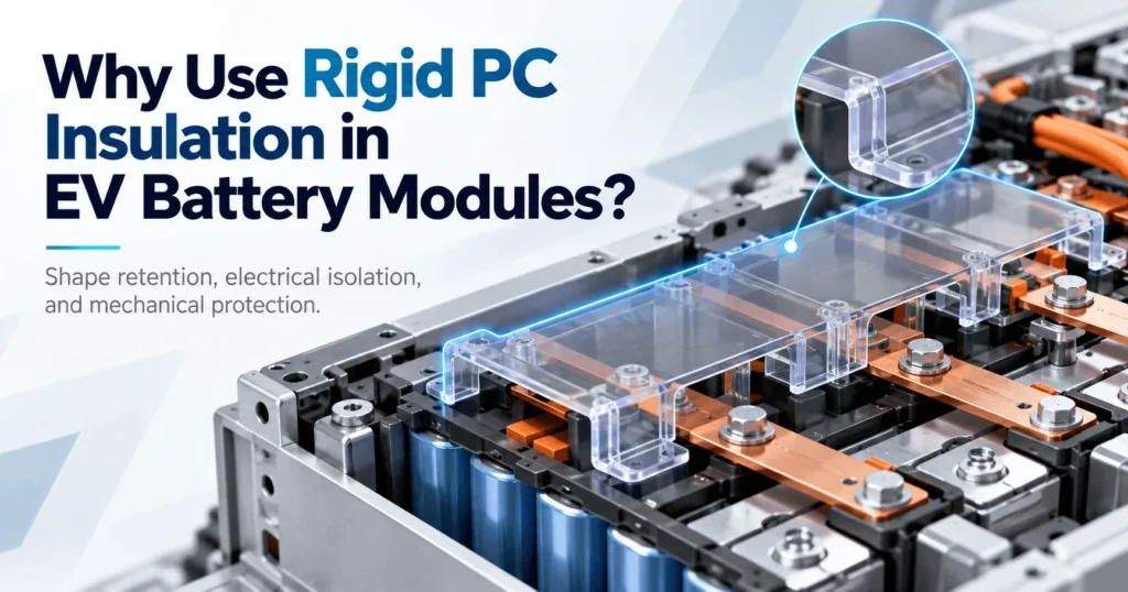
Why Use Rigid PC Insulation in EV Battery Modules?
Table of Contents
A thin dielectric film can isolate two surfaces, but what happens when the insulation part must also stay flat, bridge an opening, protect a conductor from nearby hardware, or remain in a repeatable position during module assembly? In those locations, electrical insulation is only part of the design problem. Engineers may need an insulating component with enough stiffness and toughness to maintain its intended geometry. That is the engineering space where rigid or semi-rigid polycarbonate, or PC, becomes useful inside EV battery modules.
Rigid PC insulation is used in EV battery modules when engineers need an electrical barrier that can also retain its shape, protect against mechanical contact, maintain separation between components, and remain stable during assembly. Compared with flexible PET or PI films, an appropriately selected PC grade and component geometry can function as a self-supporting cover, shield, spacer, or large-area dielectric barrier. Rigidity is not automatically better, however. The correct insulation architecture depends on voltage, geometry, unsupported span, mechanical loads, temperature, available space, flammability requirements, manufacturing method, and finished-part validation.
Key Takeaways
- Rigid PC is valuable when an insulation component must maintain a defined shape or position, not merely provide a dielectric layer.
- Rigidity is a functional property, not proof that a PC part is a structural load-bearing member.
- Flexible PET/PI films, compressible foams, rigid PC, FR4, mica, and thermal barriers solve different mechanical, electrical, and thermal problems and are often complementary.
- Thickness influences PC stiffness, but unsupported span, bends, ribs, holes, slots, fasteners, temperature, and boundary conditions can be equally important.
- A material data sheet is a screening tool. The final die-cut, CNC-cut, formed, laminated, or fastened component must be validated in representative module conditions.
What Does “Rigid Insulation” Mean in an EV Battery?
In battery engineering, rigid insulation should not be interpreted simply as a hard material. The more useful definition is functional: an insulation component is rigid or semi-rigid when it can retain a designed geometry and resist excessive deflection during handling, installation, and normal service. That behavior can help the part remain flat, span a gap, preserve separation from metal hardware, or carry locating features without folding like an unsupported film.
That does not automatically make the part structural. A PC shield may hold its own shape while carrying little or no module load. The cell stack, end plates, tie rods, enclosure, or frame may still carry compression, crash, and durability loads. Confusing self-supporting insulation with a load-bearing structural member can lead to excessive fastener loads, unsupported spans, creep, or deformation that the polymer was never intended to carry.
Rigidity also exists on a continuum. A thin PC film can remain flexible, while a thicker sheet or a formed geometry can behave much more like a cover. Grade, temperature, span, width, ribs, bends, mounting method, and local openings all influence the apparent stiffness of the finished part. For this reason, engineers should specify the required function and deflection behavior rather than relying on the word ‘rigid’ alone.
Why Do Some Battery Insulation Parts Need Rigidity?
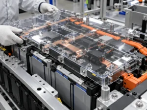
Maintain physical separation
Electrical isolation often depends on keeping conductive parts in predictable positions. A self-supporting PC barrier can help maintain cell-to-metal, terminal-to-cover, module-to-frame, or conductor-to-hardware separation where an unsupported flexible film could sag, fold, or move. The PC component does not replace the required creepage and clearance design; it can make the intended geometry easier to preserve in production.
Protect exposed electrical areas
Battery modules contain fasteners, brackets, harnesses, sensing hardware, and metal edges in addition to cells and conductors. A shaped PC cover can provide a physical boundary around an exposed electrical area and reduce the chance of incidental contact during assembly or service. Its toughness can also protect a more delicate insulation layer beneath it. Sharp metal burrs and uncontrolled point loads should still be corrected at the source rather than delegated to the polymer.
Bridge openings and cavities
A cover may need to span a cavity above a busbar, terminal region, sensing circuit, or module opening. A very thin film can provide excellent dielectric isolation when supported by another surface, but it may not hold a defined three-dimensional relationship across an unsupported gap. A PC part with suitable thickness and geometry can bridge that opening while retaining access windows, tabs, and mounting features.
Improve assembly stability
Repeatable assembly is an increasingly important insulation function. Rigid or semi-rigid parts can incorporate locating tabs, holes, slots, asymmetric poka-yoke geometry, adhesive zones, or visible edges that make orientation and inspection easier. A robot or operator can place a defined component more consistently than a loose film in some designs. The advantage is application-specific: thin films on release liners can be equally automation-friendly when the substrate fully supports them.
Where Is Rigid PC Insulation Used in EV Battery Modules?
Rigid PC should be selected by function rather than by a generic location list. The following examples show where shape retention may add value without implying that PC is mandatory in every architecture.
| Location | Function | Why Rigidity Helps | Main Design Concern |
| Module end areas | Electrical separation from metal structures | Maintains a defined barrier and can carry locating features | Compression, fasteners, local edge contact |
| Busbar covers | Protect and isolate high-voltage conductors | Self-supporting cover geometry and repeatable placement | Creepage, clearance, terminal access |
| Terminal shields | Limit accidental contact | Retains a protective shape around exposed hardware | Access, fastening, serviceability |
| Module/top covers | Large-area dielectric protection | Helps control flatness and prevents folding | Unsupported span, thermal expansion |
| Metal frame interfaces | Separate live or cell structures from metal | Maintains physical boundary | Sharp edges, tolerance stack |
| FPC/sensing covers | Mechanical protection plus insulation | Protects thin electronics from nearby hardware | Space, connector access |
| Large insulation panels | Defined barrier across a broad area | Shape retention supports handling and assembly | Thickness, flatness, mounting |
Why Is PC Suitable for Rigid Battery Insulation?
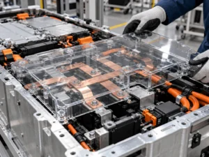
Electrical insulation
Polycarbonate is an insulating engineering thermoplastic, and established PC film suppliers publish grades intended for electrical applications. That makes PC a credible candidate for solid dielectric barriers. The exact dielectric behavior, insulation resistance, tracking performance, and flammability classification must be checked on the specific grade and relevant thickness. A generic PC property should not be transferred automatically to a purchased flame-retardant film or converted part.
Insulation coordination remains a system problem. IEC 60664-1:2020+A1:2025 treats clearances, creepage distances, and solid insulation as distinct but related elements. The applicable vehicle, battery, OEM, and component requirements determine the final design, but the principle is important: adding a rigid PC sheet does not erase the need to review air paths, surface paths, pollution, interfaces, and test voltage.
Toughness without assuming structural strength
One reason PC is attractive is that stiffness can coexist with toughness. Commercial PC films are marketed for good stiffness, toughness, elasticity, and electrical insulation. In a battery module, that combination can help a cover survive handling without behaving like a brittle board. It still does not mean every PC grade can tolerate the same fastener preload, bend radius, impact, or temperature. Those limits remain grade-, thickness-, geometry-, and process-dependent.
Dimensional stability and shape retention
A large dielectric panel is easier to position when it remains close to the intended shape. PC can support defined perimeters, access windows, tabs, and mounting features while providing a clean surface for identification or adhesive lamination. Flatness should not be assumed, especially for large thin parts: residual stress, asymmetric adhesive, forming, storage, thermal cycling, and differential expansion can create curl or distortion.
Manufacturability
PC film and sheet can be converted by die cutting and, where appropriate, CNC cutting. Selected grades can also be formed, laminated, or supplied with pressure-sensitive adhesive. The best process depends on thickness, geometry, prototype maturity, tolerance, volume, protective masking, and whether the part requires folds or formed features. A converter should review the drawing before tooling so narrow webs, small holes, internal radii, and adhesive registration do not become avoidable production risks.
Rigid PC vs Flexible PET and PI Insulation
Rigid PC and flexible films should not be treated as competing technologies with one universal winner. PET and PI are valuable when very thin, conformable insulation is needed. PC becomes more attractive when the insulation must behave as a cover or defined mechanical barrier.
| Design Requirement | Rigid / Semi-Rigid PC | PET / PI Film | Foam |
| Shape retention | Strong use case when geometry and thickness support it | Limited without support | Generally compliant rather than shape-retaining |
| Very thin dielectric layer | Possible, but rigidity falls as thickness decreases | Strong use case | Usually thicker and functionally different |
| Conformal wrapping | Limited by grade, thickness, and bend geometry | Strong use case | Not a wrapping film |
| Protective cover/shield | Strong use case | Usually needs support or attachment | Provides compliance, not a hard cover |
| Tolerance compensation | Limited | Limited | Strong use case when compression is designed |
| Mechanical shielding | Useful against handling/contact within design limits | Depends strongly on thickness/support | Soft protection rather than rigid shielding |
| Space efficiency | Application-dependent | Often excellent | Consumes gap by design |
Many modules use both. A thin PET or PI film may insulate a wrapped conductor or conformal surface, while a PC cover protects the area mechanically. Silicone foam may sit elsewhere to manage cell swelling, vibration, or tolerance. Assigning one clear job to each layer is usually more robust than asking a single material to provide every electrical, mechanical, thermal, and fire function.
Rigid PC vs FR4 for Battery Module Insulation
FR4 is a glass-reinforced thermoset laminate with substantially different structural behavior from unreinforced PC film or sheet. It is commonly considered where a rigid electrical insulator must also provide stronger mechanical support, mounting stiffness, or board-like behavior. PC is often more attractive for lighter covers, shields, liners, and large die-cut shapes where toughness, lower mass, and polymer converting are useful.
The key question is not which material is ‘better,’ but how much structural duty the insulation component must carry. If the part mainly needs to retain shape and protect a region, PC may provide sufficient rigidity. If it must support hardware or maintain geometry under higher sustained mechanical load, FR4 or another structural laminate may deserve evaluation. Fasteners, creep, temperature, moisture, thickness, machining, and weight all enter the decision.
When Is Mica More Appropriate Than Rigid PC?
Mica should be evaluated when the dominant failure case involves severe heat, flame-facing exposure, hot gas, conductive particles, or the need to preserve dielectric integrity at temperatures beyond the intended service range of ordinary PC. In those conditions, PC’s shape retention under normal operation does not make it a high-temperature firewall.
A hybrid design can use mica for the high-temperature surface and PC for clean geometry, locating tabs, edge protection, or lower-temperature mechanical support. Boost’s existing battery content already uses this functional division. The layer order should follow the actual heat and particle path, and the laminate must be validated as a construction rather than assuming each layer retains its stand-alone rating.
How Does Thickness Affect PC Rigidity?
Thickness can strongly change bending behavior, but it should not be treated as a one-variable selection rule. For a simple plate of the same material and width, bending stiffness rises rapidly as thickness increases. Real battery parts are not ideal plates: unsupported span, bends, ribs, cutouts, fastening, forming history, temperature, and boundary conditions can dominate the result.
Values such as 0.3, 0.5, 0.8, 1.0, 1.5, or 2.0 mm can be useful prototype checkpoints when those gauges are available in the selected grade. They are not universal recommendations. A 0.5 mm part with a short supported span and formed return edge may feel much more stable than a 1.0 mm flat sheet spanning a large opening. Conversely, making a part thicker can consume clearance, increase forming difficulty, change fastener stack-up, and add unnecessary material.
Why Geometry Matters as Much as PC Thickness
Rigidity belongs to the component, not just the sheet. An unsupported rectangular panel, a folded channel, and a part with return flanges can all use the same material and nominal thickness yet deflect very differently. Geometry is therefore one of the strongest levers available before simply adding material.
| Design Factor | Why It Matters | What Engineers Should Check |
| Thickness | Changes bending stiffness, mass, space, and forming behavior | Grade availability, minimum required function, packaging |
| Unsupported span | Long spans can sag or deflect | Support points, maximum deflection, vibration |
| Bends / formed edges | Can stiffen the part but introduce forming stress | Bend radius, grain/process direction, springback |
| Holes / slots | Remove material and create local stress/clearance changes | Edge distance, web width, tolerance |
| Fasteners | Can locate the part but introduce preload and conductive hardware | Washer area, torque/preload, electrical separation |
| Temperature | Polymer stiffness changes with temperature and aging | Local hot spots, cycles, grade data |
| Adhesive | Can improve retention but change flatness and stack-up | Coverage, liner, creep, rework |
| Sharp metal edges | Can create local point loads | Burr control, radius, protective geometry |
| Tolerance stack | Changes fit and local compression | Worst-case assembly, interference, locating scheme |
How Do Holes and Fasteners Affect Rigid PC Parts?
Holes are often necessary for locating, service access, terminals, or fasteners, but they remove material exactly where local stress can be high. Small edge distances or narrow webs can crack or deform during assembly. Conductive fasteners can also alter the electrical geometry by bringing metal through an otherwise insulating panel.
DFM should review hole diameter, hole-to-edge distance, washer contact, fastener preload, local bearing stress, slot length, and the tolerance between the hole and the live component. If the fastener is part of the electrical boundary, creepage and clearance around it require explicit review. The insulation part should not be expected to compensate for uncontrolled torque or a burr under the washer.
How Does Temperature Affect PC Rigidity?
Polymer stiffness is temperature-dependent. A PC part that feels very rigid at room temperature can deflect more at elevated temperature, and long-term loading can introduce creep. Local hot spots near terminals, fuses, contactors, or resistive joints may therefore matter more than the pack’s average temperature.
Thermal cycling can also reveal residual forming stress, differential expansion, adhesive curl, or fastener constraint. Engineers should use the specific grade’s temperature-dependent mechanical data and long-term ratings where available, then test the finished geometry under representative load. A generic statement such as ‘PC withstands X degrees’ is not sufficient for a battery design.
Does Flame-Retardant PC Mean Fireproof?
No. Flame-retardant PC can carry a UL 94 classification when a specific grade and specimen thickness meet the relevant test criteria, but that does not make the material fireproof. Published Covestro grades illustrate why thickness matters: different PC formulations achieve V-0 at different stated thicknesses. The rating must therefore be verified for the exact purchased grade and construction.
More importantly, UL 94 is not a thermal-runaway propagation or battery-jet certification. A rigid FR-PC cover may be appropriate for electrical and mechanical insulation while a severe vent path requires mica, ceramic material, aerogel composite, or another dedicated high-temperature barrier. The battery-level failure mode should determine whether a polymer cover is protected from direct flame, hot gas, and particle impact.
Common Mistakes When Designing Rigid PC Insulation
- Assuming ‘rigid’ means structural load-bearing. A self-supporting cover is not automatically a frame member.
- Selecting PC from dielectric strength alone and ignoring geometry, creepage, clearance, contamination, and mechanical exposure.
- Assuming thicker is always better. Added thickness can consume space, alter fastener stack-up, and complicate forming.
- Ignoring unsupported span. A broad flat panel can deflect even when the material itself is relatively stiff.
- Placing holes and slots without checking remaining web width, edge distance, and local electrical paths.
- Allowing sharp metal edges or burrs to create concentrated contact against the polymer.
- Ignoring temperature-dependent stiffness, creep, thermal cycling, and long-term aging.
- Treating UL 94 V-0 as proof of thermal-runaway protection.
- Ignoring assembly tolerance and designing only to nominal CAD geometry.
- Using raw sheet data as if it were the performance of the final die-cut, formed, bonded, and fastened component.
How Do You Design Die-Cut Rigid PC Insulation?
A production-ready PC insulator should follow a component-development sequence: material and functional requirements, drawing, DFM, prototype, validation, and then production. Starting with tooling before the function is defined can lock in unnecessary holes, tight tolerances, difficult internal corners, or an adhesive layout that later interferes with assembly.
Die cutting is efficient for repeatable two-dimensional profiles, holes, slots, windows, tabs, and adhesive-backed constructions at production volume. CNC cutting is useful for early prototypes, thicker or lower-volume parts, or designs that are still changing. If the component needs folds or formed geometry, the PC grade, thickness, bend radius, forming process, masking, and springback should be reviewed separately.
Adhesive integration deserves its own DFM review. Pressure-sensitive adhesive can simplify placement, but it adds thickness, changes rework behavior, can create local stress if applied asymmetrically, and may contribute to curl on large thin parts. Release-liner geometry can also determine whether operators or automated equipment can pick and place the component reliably.
Finished PC Part vs Raw PC Sheet
A raw PC sheet is not the final insulation system. Die cutting introduces edges; CNC machining introduces tool paths; forming introduces residual stress; holes remove load-bearing area; fasteners introduce preload; adhesive changes the stack; temperature changes modulus; and assembly tolerances determine whether the part is flat, compressed, or distorted.
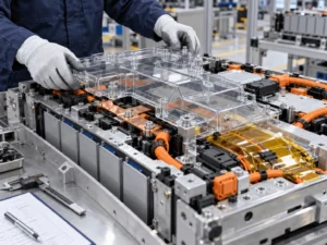
Finished-part validation should therefore represent the real component and neighboring hardware. Depending on the application, that may include dimensional inspection, fit checks, electrical withstand or insulation tests, vibration, thermal cycling, humidity conditioning, aging, mechanical contact, fastener assembly, adhesive retention, and visual inspection after exposure. The exact test plan belongs to the OEM, Tier 1, or program requirements; the converter’s role is to produce representative parts and maintain the agreed material and geometry.
Industry Insights for Rigid Battery Insulation
1. Electrical and mechanical functions are converging
Compact modules leave less room for separate protective structures. A dielectric part may now also need to locate, shield, protect, or support assembly. That favors component-level design rather than selecting insulation from one datasheet value.
2. Flexible and rigid insulation are complementary
Very thin PET/PI films remain highly useful for conformal dielectric coverage. Rigid PC addresses a different need: defined geometry and mechanical separation. Mature designs often use both in different locations.
3. Geometry can dominate nominal thickness
A bend, flange, support point, or shorter span can change deflection dramatically without changing material. DFM discussions should therefore include stiffness targets and support conditions, not only sheet gauge.
4. Assembly repeatability is part of insulation performance
A theoretically adequate barrier that is difficult to orient or keep in place can create production variation. Locating features, liner design, visual inspection, and automated placement should be considered early.
5. Finished-part validation matters more than datasheet comparison
Raw material properties screen candidates; the installed component determines whether the design works. Holes, forming, adhesive, fasteners, temperature, and aging can all change performance.
6. Higher voltage does not automatically mean thicker PC
Higher-voltage architectures increase the importance of insulation coordination, but the response may involve geometry, creepage, clearance, solid insulation, barriers, and system tests rather than a simple increase in polymer thickness.
Engineering Selection Checklist
- Define the installation location and the primary function of the PC part.
- Identify working voltage, relevant transient/test conditions, and the intended solid-insulation role.
- Review creepage and clearance around terminals, fasteners, openings, and nearby metal.
- Define why rigidity is needed: shape retention, bridging, shielding, spacing, handling, or assembly stability.
- Measure unsupported span and identify all support or fastening points.
- Map sharp edges, burr-sensitive interfaces, point loads, and possible mechanical contact.
- Review holes, slots, tabs, narrow webs, internal corners, and edge distances.
- Define operating temperature, local hot spots, thermal cycles, and aging conditions.
- Verify flame classification on the exact grade and relevant thickness if required.
- Confirm available space and worst-case tolerance stack rather than nominal clearance only.
- Define adhesive, protective masking, liner, identification, and placement method.
- Validate representative finished parts in the intended module assembly.
RFQ Checklist for Rigid PC Battery Insulation
- 2D drawing and 3D CAD when available.
- Installation location and a short description of the component’s function.
- Specified PC grade, approved material list, or required properties if the grade is open.
- Nominal thickness and acceptable alternatives for prototype evaluation.
- Working voltage and relevant insulation/test requirements.
- Operating, peak, and environmental temperature conditions.
- Required flame classification and the thickness at which it must apply.
- Overall dimensions, holes, slots, bend lines, tabs, and critical edge distances.
- Critical tolerances separated from general dimensions.
- Adhesive type, adhesive-free zones, protective film, and release-liner requirements.
- Prototype quantity, expected annual volume, packaging, labeling, and inspection needs.
- Finished-component validation requirements and any required material documentation.
How Boost Insulation Supports Rigid PC Battery Parts
Boost Insulation’s current EV battery module page describes DFM review, material and thickness review, die cutting, CNC processing, multilayer lamination, and rapid prototyping for battery insulation components. Those capabilities are relevant to rigid PC because the design usually needs more than a rectangular sheet: holes, slots, tabs, adhesive zones, protective masking, and critical interfaces have to be converted into a repeatable finished part.
For a new rigid PC project, the most productive starting point is a drawing plus the functional requirements. A manufacturability review can identify which dimensions are electrically or mechanically critical, whether die cutting or CNC is more appropriate for the current stage, how adhesive and liner should be integrated, and which features should be simplified before production tooling. Prototype parts can then be evaluated for fit, deflection, assembly, and the customer’s required validation tests.
Frequently Asked Questions
Why is rigid PC used in EV battery modules?
Rigid or semi-rigid PC is used when an insulation part must provide electrical separation while also retaining a defined shape, protecting an area from incidental mechanical contact, spanning an opening, or supporting repeatable assembly. The required stiffness depends on grade, thickness, geometry, temperature, span, and mounting. PC is not automatically the right choice when flexibility, compression, extreme-temperature survival, or structural load carrying is the dominant function.
Is rigid PC better than flexible PET insulation?
No universal ranking is appropriate. PET is often excellent for thin, flexible, conformal dielectric insulation. PC becomes more useful when the component must behave like a self-supporting cover, shield, or defined barrier. Some battery assemblies use PET for surface insulation and PC for mechanical protection in the same system. The choice should follow the actual electrical, mechanical, temperature, space, and manufacturing requirements.
Is rigid PC structural insulation?
It can provide structural shape to an insulation component, but that does not automatically make it a load-bearing battery structure. A PC cover may retain its geometry and bridge a small opening while the module frame, end plates, or other hardware carries the real mechanical loads. If the insulation must support significant sustained load or hardware, FR4 or another structural material may need to be evaluated.
How thick should rigid PC battery insulation be?
There is no universal thickness. Candidate thickness depends on the specific PC grade, required electrical function, unsupported span, desired deflection, holes and cutouts, temperature, available space, forming method, fasteners, flame classification, and validation plan. Example gauges such as 0.3, 0.5, 0.8, 1.0, 1.5, or 2.0 mm should be treated as prototype options only when available in the selected grade.
Can rigid PC insulation be die cut?
Yes. PC film and sheet can be die cut into custom perimeters, holes, slots, windows, and tabs, and can be laminated with adhesive when the construction permits. CNC cutting can be useful for prototypes, low-volume builds, thicker parts, or frequently changing designs. The converter should review narrow webs, hole size, corner radii, masking, adhesive registration, tolerance, and any forming requirements before production.
Can PC insulation be used near battery busbars?
Yes, an appropriate PC grade can be used as a busbar cover, shield, or solid dielectric barrier when the electrical, thermal, mechanical, and flammability requirements are met. Busbar applications still require dedicated creepage, clearance, terminal, fastener, and conductor-edge review. This article focuses on rigidity as a module-design function rather than the detailed high-voltage busbar insulation architecture.
Is UL94 V-0 PC suitable for thermal runaway protection?
A V-0 classification can be useful for selecting a flame-retardant polymer, but it does not prove that a PC part can serve as a thermal-runaway barrier. UL 94 behavior is tied to the specific material and tested thickness. Direct flame, hot gas, particle impact, and extreme-temperature dielectric survival may require mica, ceramic, aerogel-based, or other dedicated barrier materials validated for the actual battery failure scenario.
When should FR4 or mica be used instead of PC?
FR4 may be more appropriate when the electrical insulator also needs substantially greater structural stiffness or mechanical support. Mica may be more appropriate when severe heat, flame-facing exposure, hot gas, or high-temperature dielectric integrity dominates. PC is often useful for tough, lightweight, dimensionally defined covers and barriers under less severe thermal exposure. Hybrid constructions can combine these roles.
Conclusion
Rigid PC insulation earns its place in an EV battery module when shape retention itself is part of the insulation function. A well-designed PC component can isolate electrically while remaining visible, locatable, self-supporting, and mechanically protective during assembly. Its value is not simply that PC is ‘stronger’ than a film; it is that the component can preserve a deliberate geometry.
The final decision should still be made at component level. Grade, thickness, unsupported span, holes, fasteners, temperature, adhesive, forming, tolerances, and neighboring structures all affect performance. Where flexibility, compression, structural load carrying, or severe thermal exposure dominates, PET/PI, foam, FR4, mica, aerogel, or a multilayer construction may be more appropriate.
CTA: If you are developing rigid PC insulation for an EV battery module, send your drawing, installation location, PC grade or material requirements, thickness, operating temperature, electrical requirements, adhesive needs, prototype quantity, and annual volume for a manufacturability review.
Related Posts:
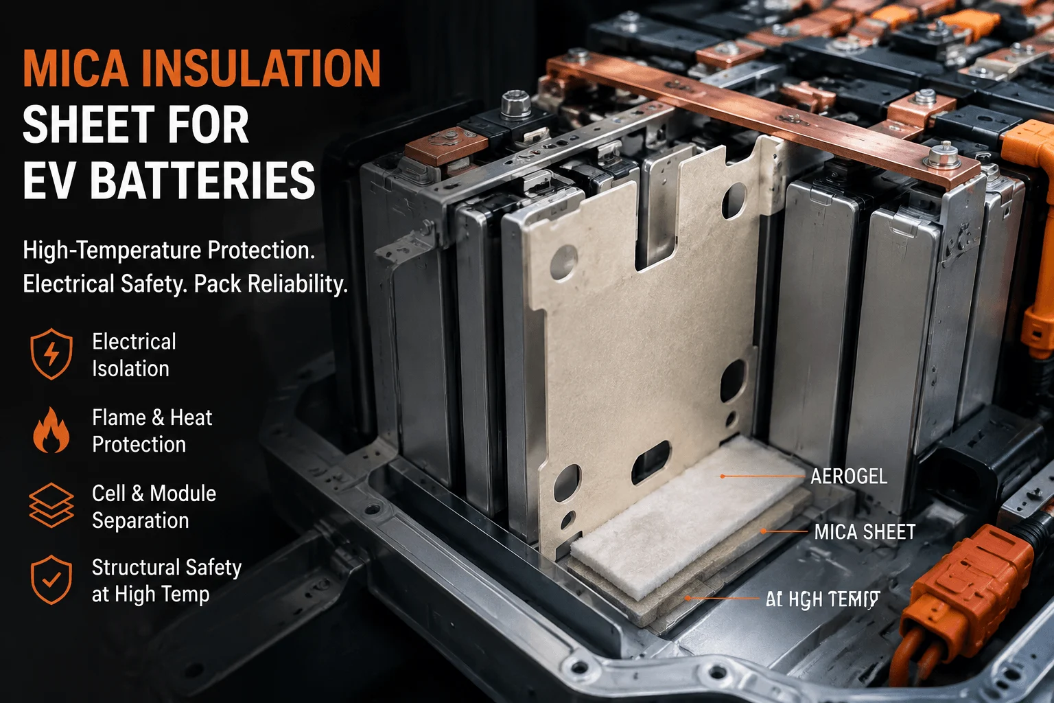
How Does a Mica Insulation Sheet Protect EV Batteries?
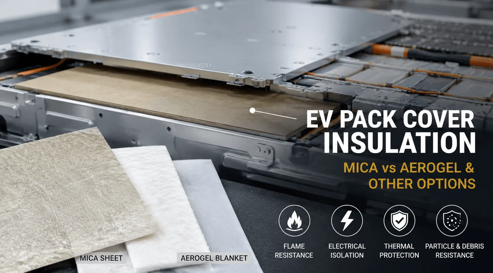
Which Insulation Material Is Best Under EV Pack Covers?
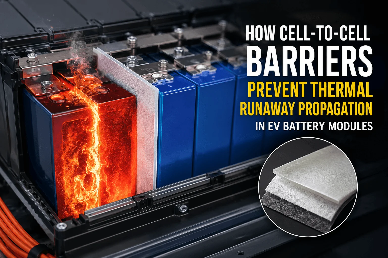
How Do Cell-to-Cell Barriers Prevent Thermal Runaway?
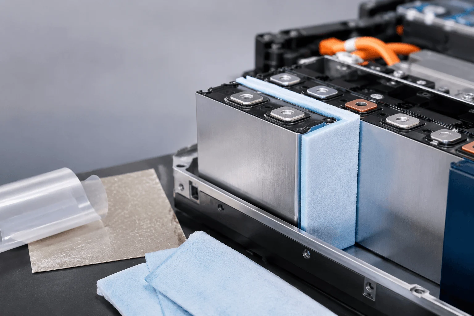
How Do You Select Aerogel Thickness Between Cells?
Why Does EV Battery Insulation Need UL94 V-0?
How to Choose EV Battery Cell Insulation Pads?
 betty wong
