
Which Insulation Material Is Best Under EV Pack Covers?
Table of Contents
What happens to the underside of an EV battery pack cover when a single cell vents flame, hot gas, and conductive debris upward? If the insulation layer is selected only by thermal conductivity or a UL 94 rating, the pack may still have a weak point exactly where a severe failure attacks it. Under-cover insulation therefore needs to be chosen around the failure mode – not around one attractive number on a datasheet.
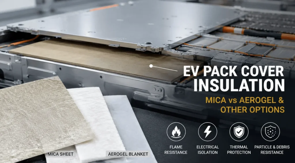
For most EV pack-cover applications, a mica-based insulation sheet is the best starting point when the layer must resist thermal-runaway flame, hot gas, particles, and high-voltage electrical exposure. Aerogel is better when ultra-low heat transfer is the main requirement, while inorganic flame-barrier papers, ceramic mats, and silicone-based barriers can be stronger in specialized designs. Many high-performance packs use a multilayer system rather than one material alone.
| Quick decision: For direct flame/hot-gas + dielectric protection under the lid, start with mica. For maximum thermal resistance per millimeter, evaluate aerogel. For optimized packs, validate a multilayer stack. |
Why Insulation Under the Pack Cover Is a Different Engineering Problem
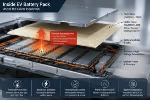
Insulation between cells and insulation beneath the pack lid are exposed to different failure mechanisms. Between cells, the design often focuses on slowing conductive heat transfer from one cell to the next while accommodating swelling and compression. Under the cover, the barrier can face a much more directional event: an upward jet of hot gas, flame, electrolyte aerosol, molten or incandescent particles, and mechanically ejected debris. At the same time, the cover may sit close to busbars, sensing circuits, module frames, fasteners, or other conductive structures. The material must therefore survive both a thermal event and an electrical event long enough for the pack-level safety strategy to work.
This distinction is easy to miss during early material screening. A material can have extremely low thermal conductivity and still be a poor burn-through shield. Another material can achieve an excellent flammability classification at a thin gauge yet soften, shrink, erode, or lose dielectric spacing under the thermal flux of a cell vent. The correct question is not, ‘Which material has the best thermal number?’ It is, ‘Which material stack remains functional under the exact heat, flame, particle, pressure, voltage, geometry, and duration expected at this location?’
The pack cover is also becoming more important as battery architecture changes. Cell-to-pack and highly integrated pack designs remove intermediate structures and use space more aggressively. Industry suppliers now explicitly describe barrier applications ‘under the lid’ and ‘above cells,’ while also noting that newer pack architectures may turn the lid itself into a structural component. That means the insulation immediately below it can no longer be treated as a generic liner. It is part of the pack’s thermal-runaway containment, electrical isolation, manufacturability, and serviceability strategy.
For sourcing teams, this makes EV pack cover insulation a system component rather than a commodity sheet. The finished die-cut part – including adhesive, reinforcement, seams, holes, cutouts, edge clearances, compression, and installation method – is what should be qualified. Two parts made from nominally the same base material can perform very differently after conversion.
What Does “Best” Mean for EV Pack Cover Insulation?
There is no universal best material for every pack cover. The best choice is the material or multilayer construction that satisfies the highest-risk functions at the lowest practical thickness, mass, cost, and manufacturing complexity. For a typical high-voltage EV pack, engineers should evaluate at least six functions before approving an under-lid barrier.
- Burn-through resistance: Can the layer resist direct flame, hot gas, and erosive jet exposure without opening a path to the cover?
- Electrical isolation: Does the finished part maintain adequate dielectric performance before and after thermal exposure, vibration, humidity, and assembly damage?
- Thermal resistance: Does the construction reduce heat transfer to the pack lid, passenger-side structure, wiring, seals, or nearby components for the required duration?
- Particle and debris resistance: Can it tolerate hot metallic particles, cell fragments, and electrolyte contamination without puncture or rapid erosion?
- Mechanical and dimensional stability: Does the barrier stay in position through vibration, thermal cycling, lid deflection, fastener loads, and pack breathing?
- Manufacturability: Can the material be die-cut, laminated, handled, installed, inspected, and traced consistently at automotive production volumes?
These functions immediately explain why mica is so often shortlisted under the lid. It is not always the lowest-conductivity option, but it can combine high-temperature inorganic content, dielectric insulation, flame resistance, dimensional stability, and good convertibility in one relatively thin component. Where conductive heat transfer is the dominant challenge, aerogel can be added or used elsewhere. Where only a thin electrical and flame barrier is required, engineered inorganic barrier papers may be sufficient. The job of material selection is to match the barrier mechanism to the actual failure mechanism.
Why Mica Is Usually the Best Starting Point Under an EV Pack Cover
For pack-lid and above-cell locations exposed to a possible thermal-runaway plume, mica is usually the strongest baseline candidate because it addresses several failure modes at once. Mica-based insulation is an inorganic mineral system with a long history in high-voltage electrical equipment. In battery applications, engineered mica paper or laminate can be converted into thin rigid, semi-rigid, or flexible barriers that maintain useful physical separation when nearby polymeric materials may have already lost shape.
The first advantage is high-temperature integrity. A pack-cover barrier does not merely need to avoid ignition; it needs to remain present. During a severe cell event, the layer can be attacked by a concentrated plume rather than by uniform oven temperature. A material that chars or shrinks away may expose aluminum or steel cover structures, adhesives, wire harnesses, pressure equalization elements, or passenger-side components. Mica’s inorganic plate-like structure makes it well suited to this type of passive fire and burn-through protection, provided the exact grade, binder, reinforcement, and thickness are validated.
The second advantage is dielectric performance. Above-cell insulation may have to continue separating energized parts from a conductive cover after the event has mechanically disrupted the pack. A dedicated thermal barrier that is electrically conductive or that becomes conductive after contamination can create a second failure mode. Mica is attractive because the same converted part can provide high-temperature separation and electrical insulation. This multifunctionality can reduce layer count compared with designs that need separate fire and dielectric sheets.
The third advantage is dimensional stability. Under-cover insulation frequently includes large flat areas, narrow bridges around fasteners, openings for vents and service features, and local clearances around busbars. A semi-rigid sheet can hold those features more predictably than a very soft blanket. That matters for automated assembly, adhesive placement, vision inspection, and consistent creepage/clearance geometry.
The fourth advantage is conversion flexibility. Mica sheets can be CNC-cut or die-cut, laminated with pressure-sensitive adhesive, reinforced with film or fabric, combined with silicone foam, or integrated with aerogel and other thermal layers. For a Chinese precision-converting supplier, this makes mica commercially attractive because engineers can tune the finished component rather than being locked into one monolithic raw material.
Mica still has limitations. It can be more brittle than polymer films, may generate edge damage or dust if poorly processed, and is not automatically the best material for minimizing steady-state heat conduction per millimeter. Thin unsupported mica can crack if the cover flexes substantially. Binder chemistry and reinforcement change both high-temperature behavior and handling. The correct engineering position is therefore not ‘mica is always best,’ but ‘mica is often the best structural thermal-and-electrical barrier platform for the under-lid location.’
Mica vs Aerogel: Which Is Better Under the Lid?
Aerogel and mica are frequently compared because both appear in EV thermal-runaway designs, but they solve different problems. Aerogel’s core advantage is exceptionally low thermal conductivity in a thin, lightweight format. That makes engineered aerogel barriers particularly valuable between prismatic or pouch cells, where slowing cell-to-cell heat transfer while preserving volumetric efficiency can be decisive. Automotive aerogel suppliers also design products to maintain thermal performance under compression and through end-of-life mechanical cycling.
Under a pack cover, however, the primary threat may be direct plume impingement rather than ordinary conduction. If a vent points upward, the barrier can face flame, grit, hot particles, and high-velocity gas. An aerogel product can be engineered for severe thermal exposure, but engineers should not assume that low conductivity alone proves adequate resistance to erosion, burn-through, puncture, or post-event dielectric requirements. The exact composite and protective facing matter.
This is why a mica-plus-aerogel construction can be more effective than choosing either material in isolation. Mica can provide the flame-facing, particle-resistant, dielectric layer; aerogel can add thermal resistance behind it to reduce the temperature transmitted to the lid. The order of layers should follow the expected heat source and the manufacturer’s validated stack-up. In a thin pack where every millimeter matters, a hybrid can provide better functional density than a thick single-material barrier.
A useful rule is simple: if the engineering question is ‘How do we slow heat transfer through a narrow gap?’ aerogel deserves serious consideration. If the question is ‘What remains between a thermal-runaway plume and the metal pack cover while also maintaining electrical isolation?’ mica is often the better starting point.
What About Inorganic Flame-Barrier Papers?
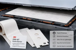
Thin inorganic flame-barrier papers are another credible under-cover option. 3M, for example, positions its FRB-NT flame barrier for areas above cells to enhance electrical insulation after a cell burst. This is important industry evidence because it confirms that the above-cell location can be solved with a thin, converted inorganic sheet rather than only a thick blanket.
The advantage of this category is very low thickness, good die-cut convertibility, and useful dielectric/flame performance. It can be attractive where the cover is close to the cells and the design has little Z-height available. It may also work well as one layer in a laminate.
The trade-off is that a thin paper-like barrier has less inherent structural stiffness than a mica board and may offer less thermal resistance than an aerogel layer. Whether it survives a specific plume depends on thickness, composition, support, distance from the vent, and exposure. Engineers should test the finished under-lid assembly rather than transfer a generic flame rating directly into a thermal-runaway claim.
What About Ceramic Fiber, Microporous, and Silicone-Based Barriers?
Ceramic-fiber and microporous insulation materials can provide excellent high-temperature capability and low heat transfer. They are useful when the pack has enough space for a thicker blanket or when the cover needs strong thermal isolation from a large heat source. Their disadvantages can include bulk, compressibility, particle or fiber handling requirements, edge sealing, and more difficult automation. A protective facing or laminate is often needed for clean assembly.
Silicone-based thermal-runaway barriers and foams provide a different set of benefits. They can conform to uneven surfaces, fill gaps, absorb tolerance, damp vibration, and in some formulations combine fire resistance, dielectric strength, and debris protection. Dispensed or molded silicone barriers can also cover complex three-dimensional geometry that is difficult to protect with a flat sheet. The trade-offs may include cure process, thickness control, mass, rework difficulty, and formulation-specific aging behavior.
Flame-retardant PC, PET, PI, and other polymer films remain valuable for electrical insulation and assembly. They are especially useful around busbars, tabs, service disconnects, and areas where thin dielectric isolation is the main requirement. However, a UL 94 V-0 polymer film should not automatically be treated as equivalent to a thermal-runaway burn-through barrier. UL 94 classification evaluates material flammability under defined small-scale conditions; it does not by itself prove resistance to a high-energy battery vent plume. In demanding under-lid zones, polymer films are often better used as supporting dielectric or handling layers within a validated stack.
EV Pack Cover Insulation Material Comparison
| Material | Best-fit under-cover role | Main strength | Main trade-off |
| Mica sheet / laminate | Flame-facing and dielectric barrier | High-temperature integrity + electrical isolation + shape retention | Not the lowest thermal conductivity; grade/binder and brittleness matter |
| Aerogel composite | Thermal resistance layer | Very low heat transfer at low thickness/weight | Direct jet/particle durability and dielectric behavior depend on exact composite |
| Inorganic flame-barrier paper | Ultra-thin above-cell barrier | Thin, die-cuttable, good flame/dielectric performance | Less stiffness and thermal resistance than thicker systems |
| Ceramic / microporous mat | Extreme thermal isolation | High-temperature capability and strong thermal resistance | Can be thicker, compressible, or harder to handle cleanly |
| Silicone-based barrier / foam | Conformal gap-filling or 3D barrier | Conformability, cushioning, sealing; some grades add fire/dielectric protection | Thickness, cure/processing, mass, aging and rework vary by formulation |
| FR PC/PET/PI film | Supporting dielectric/handling layer | Thin electrical isolation and easy conversion | Do not assume a thin polymer film alone is a burn-through barrier |
Note: “Best” depends on the exact cell, vent direction, exposure, mounting, voltage, thickness, and validation method. Supplier datasheet values are not interchangeable across constructions.
A Practical Material-Selection Matrix for EV Pack Covers
The following decision logic is more useful than ranking materials by one property. Start with the dominant failure mode, then identify the secondary functions the same part must carry.
- Choose mica first when the dominant risk is direct flame, hot gas, hot particles, or burn-through and the part must also provide high-voltage electrical insulation.
- Choose aerogel first when the dominant requirement is maximum thermal resistance in minimum thickness, especially where conductive heat transfer is more important than direct jet erosion.
- Choose an inorganic flame-barrier paper when Z-height is extremely limited and the design mainly needs a thin above-cell flame/dielectric shield that can be supported by the cover or another substrate.
- Choose ceramic or microporous insulation when very high thermal resistance is required and the design can accept greater thickness, compressibility, or more complex handling.
- Choose silicone-based barriers when geometry is three-dimensional, gap-filling is required, or the barrier must combine conformability, vibration control, sealing, and thermal-runaway protection.
- Choose a multilayer composite when no single material can meet flame, thermal, dielectric, thickness, mass, and assembly requirements simultaneously.
How Cell Format Changes the Best Under-Cover Insulation
Cell format changes both the location and character of the threat. A cylindrical-cell pack can contain many potential vent sources distributed across a large area. The top of the cell array may include bus structures, current collectors, cooling interfaces, or potting materials. Under-cover insulation may therefore need a broad barrier with local openings that preserve designed vent paths while shielding the lid from flame and debris. Large-area mica or a mica-based laminate is often attractive because it can be converted into precise sheets with controlled openings and reinforced areas.
Prismatic cells concentrate more energy in each unit and may have defined vent directions. If vents face upward, the cover barrier may see a smaller number of more energetic jets. Engineers may use a robust mica shield, an engineered above-cell barrier, or a multilayer stack that combines a hard flame-facing sheet with a low-conductivity layer. Between prismatic cells, aerogel or compression/thermal barrier products may play a larger role than they do at the lid.
Pouch-cell systems add another mechanical variable: swelling and compression management. The under-cover layer may not need to act as a compression pad, but lid movement and module growth can change clearances over life. Soft insulating layers can accommodate movement, while a rigid mica panel may need strategic slots, segmentation, adhesive islands, or a supporting foam to avoid cracking under repeated flexure.
Cell-to-pack and structural-battery designs raise the stakes further. When modules and cross-members are reduced, the cover, cell array, and bonding system become more integrated. The insulation layer must coexist with structural adhesive, serviceability requirements, pressure management, vent channels, and tighter packaging. In these architectures, the ‘best material’ is increasingly a designed stack whose thermal and mechanical functions are verified together.
Do Not Block the Vent Path
One of the most important under-cover design rules is also one of the easiest to violate: insulation must not defeat the pack’s gas-management strategy. Thermal runaway can generate rapidly expanding hot gases, and a pack may rely on directional venting, pressure relief devices, channels, chimneys, or controlled exhaust zones. A large die-cut sheet that looks perfect in CAD can become dangerous if it covers a relief opening, delaminates into a vent path, traps pressure, or redirects a jet toward sensitive components.
Barrier geometry should therefore be developed with the vent path, not after it. Hole size, edge distance, overlap, adhesive location, unsupported spans, and the direction of possible delamination should be reviewed in DFM. Where a barrier sits over cell vents, the design may require vent apertures, sacrificial zones, reinforced edges, or a separate deflector. Material suppliers and converters should receive the intended vent direction and prohibited blockage zones as part of the drawing package.
This is another reason final-stack testing matters. A raw sheet can pass a torch test and still fail in the pack if adhesive releases, a cut edge erodes first, or pressure lifts the barrier from the cover. Qualification needs to reproduce realistic mounting and gas flow as closely as practical.
2026 Industry Insight: Pack-Cover Barriers Are Moving From “Nice to Have” to System-Level Safety Hardware
The regulatory direction is making passive thermal-runaway protection more consequential. China’s GB 38031-2025, published in 2025 and effective from July 1, 2026, replaced the previous edition and raised the thermal-propagation safety bar. Official Chinese industry guidance describes the shift from the former focus on providing a warning before fire or explosion to requirements that the tested battery pack or system not catch fire or explode under the specified thermal-propagation test, while still providing an alarm and addressing occupant exposure to smoke. The revision also adds bottom-impact and post-fast-charge safety testing.
The standard does not prescribe mica, aerogel, or any specific insulation. That is precisely why material engineering becomes more important. OEMs and battery suppliers must prove the behavior of the complete pack. The under-lid barrier is one element in a broader strategy that includes cell safety, vent direction, module spacing, cooling, electrical isolation, pressure relief, detection, enclosure design, and software controls.
A second industry trend is higher integration. Battery manufacturers continue to pursue higher cell-to-pack volume utilization, fewer intermediate structures, and faster manufacturing. Removing structural redundancy can improve energy density and cost, but it also reduces the number of layers available to absorb a failure. As the cover becomes closer to active cells and more structurally significant, a thin multifunctional barrier with fire, dielectric, and manufacturing value becomes more attractive.
A third trend is that buyers increasingly ask for lifecycle performance, not just new-material data. Aerogel suppliers emphasize thermal and mechanical behavior under compression through end of life. The same principle should be applied to pack-cover insulation: thermal cycling, vibration, humidity, adhesive aging, contamination, and cover deflection can alter the gap and the barrier’s condition long before any safety event occurs. A 2026 sourcing specification should define what the barrier must do after aging, not only on day one.
Why Thickness Alone Is a Poor Specification
RFQs often begin with a statement such as ‘need 1.0 mm mica’ or ‘need 2.0 mm aerogel.’ Thickness is important, but it does not define performance. A one-millimeter mica laminate can vary in mica type, binder content, reinforcement, density, dielectric strength, flexibility, edge quality, and flame behavior. Aerogel at the same nominal thickness can vary in density, compression curve, facing, dust control, and thermal conductivity under pressure.
For under-cover applications, thickness should be selected after defining thermal exposure and required back-face temperature, electrical withstand requirements, mechanical support, maximum cover deflection, and available Z-height. If the barrier is adhesive-backed, include adhesive thickness in the stack. If the material compresses, define the installed thickness and pressure range rather than only the free-state thickness.
The same principle applies to air gaps. A small air gap between barrier and cover can change heat transfer and plume behavior. A tightly bonded barrier behaves differently from a mechanically retained sheet. Engineers should test the same installation condition planned for production.
DFM Details That Decide Whether the Barrier Works in Production
Once the base material is selected, conversion quality becomes a major part of risk. Automotive pack-cover barriers are often large, thin, and geometrically complex. They may include dozens of holes, cutouts around connectors and vents, narrow webs, alignment features, and adhesive zones. A robust DFM review should look beyond nominal dimensions.
- Edge condition: cracked mica edges, fiber breakout, burrs, or loose particles can reduce handling quality and contaminate the pack.
- Minimum web width: narrow sections around holes may tear or fracture during liner removal, robot handling, or lid assembly.
- Adhesive placement: full-surface adhesive can improve handling but may change thermal behavior, add combustible content, and make service more difficult. Patterned adhesive can reduce these effects but requires better registration control.
- Release-liner design: split liners, pull tabs, kiss cuts, and staged removal can materially reduce operator error on large parts.
- Flatness and warpage: large mica or laminate parts must remain flat enough for automated placement and lid closure.
- Segmentation: dividing one large barrier into zones can improve yield, reduce cracking, simplify service, and isolate design changes, but seams must not create a direct flame path.
- Hole and vent tolerance: openings that interact with vent devices, studs, busbars, or seals need process capability matched to pack tolerances.
- Cleanliness: conductive debris in a high-voltage pack can defeat the purpose of the insulation; controlled converting and inspection are important.
For this reason, the supplier should be evaluated as a converter and automotive process partner, not only as a raw-material reseller. Tooling capability, lamination control, inspection, lot traceability, APQP/PPAP support, change control, and capacity planning all affect whether the qualified laboratory sample can be reproduced at volume.
How to Test EV Pack Cover Insulation Before Release
No single coupon test proves that an under-cover barrier will work. The validation plan should move from material screening to component-level and then pack-representative testing. The exact methods depend on OEM requirements and market regulations, but a useful program normally covers electrical, thermal, mechanical, environmental, and manufacturing dimensions.
- Material screening: verify thickness, density, dielectric properties, flammability information, thermal behavior, and composition for the exact grade and construction.
- Thermal exposure: evaluate direct flame, torch, hot-gas, grit/particle, or other representative exposure with the intended layer orientation and support.
- Back-face temperature: measure temperature transmitted to the lid or protected component over the required duration rather than relying only on thermal conductivity data.
- Post-exposure dielectric check: where relevant, confirm that the remaining barrier still supports the electrical safety concept after thermal damage.
- Mechanical aging: assess vibration, shock, cover flexure, compression, and fatigue that could crack, abrade, or delaminate the part.
- Environmental aging: humidity, thermal cycling, chemical exposure, and adhesive aging should reflect vehicle life requirements.
- Assembly validation: confirm liner removal, robot pick-up, placement, fastener clearance, vent opening alignment, and lid closure at production takt time.
- Pack or module propagation testing: verify the complete barrier strategy with the actual or representative cell, vent direction, enclosure, and gas-management architecture.
What Should You Put in an RFQ for Battery Pack Cover Insulation?
A good RFQ allows the material converter to propose a better solution and quote it accurately. Sending only a PDF outline and thickness usually produces a commodity quote; sending functional requirements produces engineering feedback.
- Cell format and chemistry: cylindrical, prismatic, pouch; LFP, NMC, or other relevant chemistry.
- Barrier location: full pack lid, local above-cell shield, vent corridor, module top, busbar zone, service-disconnect area, or perimeter wall.
- Expected failure direction: vent orientation, likely plume path, protected components, and no-block zones.
- Electrical requirements: system voltage, dielectric withstand target, creepage/clearance constraints, and whether post-event isolation is required.
- Thermal target: exposure method, time, allowable back-face temperature, and any customer-specific propagation test.
- Mechanical requirements: available gap, cover deflection, compression, vibration, bend radius, and required stiffness.
- Material restrictions: halogen-free, low-smoke, RoHS/REACH, OEM restricted-substance requirements, and cleanliness limits.
- Geometry: 2D/3D CAD, hole tolerances, critical-to-quality dimensions, adhesive zones, tabs, and liner requirements.
- Program details: prototype quantity, SOP timing, annual volume, PPAP level, traceability, packaging, and destination.
Why Work With a Precision Die-Cutting Manufacturer Instead of Buying Raw Sheets?
Raw-material performance is only the beginning. An EV battery plant does not install a generic square of insulation; it installs a production part with a part number, revision, tolerance, adhesive system, packaging method, inspection plan, and traceable lot history. The converter turns material science into a repeatable component.
For overseas OEM, Tier 1, battery-pack, and energy-storage customers sourcing from China, the strongest cost advantage comes from process integration rather than simply buying cheaper sheet stock. In-house tooling, automated rotary die-cutting, CNC prototyping, multilayer lamination, controlled-environment assembly, and high-volume inspection can reduce material waste and assembly labor while improving dimensional consistency.
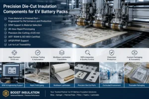
Boost Insulation positions its EV battery insulation business around this model. According to its current website, the company supports DFM and material selection, 48-hour rapid prototyping, precision die-cutting with tolerances as tight as +/-0.05 mm for applicable components, IATF 16949 and ISO 9001 quality systems, APQP/PPAP support, controlled production environments, and lot-to-lot traceability. Its EV battery insulation portfolio includes engineered mica and aerogel solutions alongside flame-retardant films, thermal pads, gels, foams, and multilayer laminates.
That range matters for pack-cover projects because the optimal part may not be ‘mica only.’ A customer may need a mica flame-facing layer with an aerogel thermal layer, a local foam spacer, a dielectric film, or patterned adhesive. A converter that can prototype several constructions from one drawing can shorten the selection loop and make cost-performance trade-offs visible before tooling and validation are locked.
Common Mistakes When Selecting Insulation Under EV Pack Covers
- Choosing by thermal conductivity alone. Low conductivity does not prove flame-jet, debris, or dielectric performance.
- Treating UL 94 V-0 as a thermal-runaway certification. It is useful flammability information, but it is not a substitute for pack-representative burn-through or propagation validation.
- Copying a cell-to-cell material to the lid. The mechanical loading and failure exposure can be completely different.
- Ignoring binder, facing, and adhesive. The weakest layer can determine how the complete laminate behaves during heat exposure.
- Testing only pristine samples. Production barriers should be evaluated after relevant thermal, humidity, vibration, and adhesive aging.
- Blocking or redirecting the designed vent path. A thermal barrier must work with gas management, not against it.
- Over-specifying one material before DFM. A slightly different construction may reduce thickness, material cost, or assembly steps while meeting the same system target.
- Qualifying the raw sheet but not the converted part. Holes, seams, cut edges, liner pull, and installation pressure can create the real failure points.
Frequently Asked Questions About EV Pack Cover Insulation
What is the best insulation material under an EV battery pack cover?
For many high-voltage pack-cover and above-cell applications, mica is the best starting material because it combines high-temperature integrity, flame and particle resistance, electrical insulation, and dimensional stability. Aerogel can be better where maximum thermal resistance per millimeter is the priority. The final choice should be validated against the actual vent direction and pack-level failure mode.
Is mica better than aerogel under a battery lid?
Mica is usually better when the lid-facing barrier must survive direct flame, hot-gas jets, particles, and electrical exposure. Aerogel is usually better when the main objective is minimizing conductive heat transfer in a narrow space. A mica-and-aerogel laminate can combine both functions when Z-height and cost allow.
Can aerogel be used under an EV pack cover?
Yes. Engineered aerogel barriers can be used in battery packs and can provide excellent thermal resistance. Under a lid, verify the exact product for flame, jet, grit, particle, compression, and dielectric requirements rather than assuming that low thermal conductivity alone is enough.
Is UL 94 V-0 polycarbonate enough for thermal runaway protection?
Not necessarily. A V-0 rating describes flammability behavior under a defined test and thickness. Severe battery thermal runaway can expose a part to much higher heat flux, hot gas, and debris. Flame-retardant PC is valuable for dielectric insulation and can be part of a multilayer design, but a demanding lid-facing zone may require mica, an inorganic flame barrier, or another validated thermal-runaway material.
How thick should mica insulation be under the pack cover?
There is no universal thickness. It depends on cell energy, vent direction, distance to the lid, flame or jet exposure, required back-face temperature, dielectric target, mechanical support, and the exact mica construction. Engineers should define performance targets first and then validate candidate thicknesses in the intended stack.
Should the barrier be bonded to the lid or installed as a free sheet?
Both approaches are possible. Bonding can simplify assembly and prevent movement, but adhesive changes the fire, thermal, and service behavior of the system. A free or mechanically retained sheet avoids some adhesive concerns but may need stronger location features. Test the intended mounting condition.
Can one insulation part protect the entire pack cover?
Sometimes, but large one-piece barriers can create handling, flatness, yield, repair, and vent-path problems. Segmented zones or local reinforcement may be more manufacturable. Seams and gaps must be arranged so they do not create a direct thermal path.
What information should I send a die-cut insulation supplier?
Send a 2D or 3D drawing, cell format, vent direction, target thickness range, voltage requirement, thermal or flame test target, adhesive preference, annual volume, PPAP requirements, and any material restrictions. Photos or a pack cross-section are also useful during early DFM.
Can Boost Insulation make multilayer pack-cover barriers?
Boost Insulation states that its EV battery insulation capability includes engineered mica and aerogel solutions, films, foam, thermal materials, precision die-cutting, lamination, rapid prototyping, and DFM support. For a production project, the exact material stack should be selected and validated against the customer drawing and safety requirements.
Final Recommendation: Start With the Failure Mode, Then Build the Stack
If an EV pack cover sits above cells that may vent upward, mica should usually be the first material screened for the lid-facing barrier. It provides a strong combination of thermal-runaway flame resistance, particle shielding, dielectric insulation, shape retention, and production convertibility. That combination is difficult to obtain from a thin polymer film or a soft thermal insulator alone.
Do not stop at mica, however. Add aerogel when the pack also needs very low through-thickness heat transfer. Consider thin inorganic flame-barrier papers when space is exceptionally tight. Use silicone, ceramic, or microporous materials where geometry, sealing, cushioning, or extreme thermal resistance justify them. In many modern battery packs, the winning design is a multilayer system in which each material is placed where its mechanism is strongest.
Most importantly, qualify the finished part in the finished location. Pack-cover insulation should be judged by burn-through behavior, back-face temperature, electrical isolation, vent-path compatibility, mechanical aging, and production repeatability – not by one datasheet value. The best EV pack cover insulation is the one that remains functional through the pack’s intended failure scenario and can still be manufactured consistently at automotive scale.
Need a Custom EV Pack Cover Insulation Part?
| If you are comparing mica, aerogel, flame-retardant film, foam, or a multilayer barrier for an EV battery lid, send Boost Insulation your drawing and application requirements. The engineering team can review material choice, thickness, vent clearances, adhesive zones, die-cut geometry, and production feasibility, then prototype the proposed construction for fit and validation. For the fastest technical review, include your CAD/PDF, cell format, pack voltage, target safety test, available Z-height, annual volume, and SOP timing. |
Technical Reference Notes for Editorial Review
These sources support the engineering and industry context used in the article. They are provided for editorial/E-E-A-T review; the blog can be published with or without a visible reference section depending on site policy.
Boost Insulation – EV Battery Module Insulation: https://boostinsulation.com/products/ev-battery-module-insulation/
Boost Insulation – Mica Insulation Sheet for EV Battery Packs: https://boostinsulation.com/mica-insulation-sheet-for-ev-battery-packs/
3M – ePowertrain & Electric Vehicle applications (above-cell and under-lid barriers): https://www.3m.com/3M/en_US/oem-tier-us/applications/epowertrain/
3M – Flame Barrier FRB-NT102 (above-cell electrical/flame barrier application): https://www.3m.com/3M/en_US/p/dc/v000532414/
Aspen Aerogels – Thermal Runaway Barriers / PyroThin: https://www.aerogel.com/industries/battery-thermal-barriers/
Von Roll – Automotive battery fire protection / mica burn-through protection: https://www.vonroll.com/app/themes/friendventure-vonroll/components/BlockBildInteraktiv/Partials/automotive/e_car_EN.htm
China National Standard Information Public Service Platform – GB 38031-2025: https://std.samr.gov.cn/gb/search/gbDetailed?id=31D72E7FB9BF92EDE06397BE0A0AC2E0
Hubei Provincial Department of Economy and Information Technology – 2026 implementation summary for GB 38031-2025: https://jxt.hubei.gov.cn/bmdt/rdjj/202606/t20260629_5966403.shtml
Related Posts:
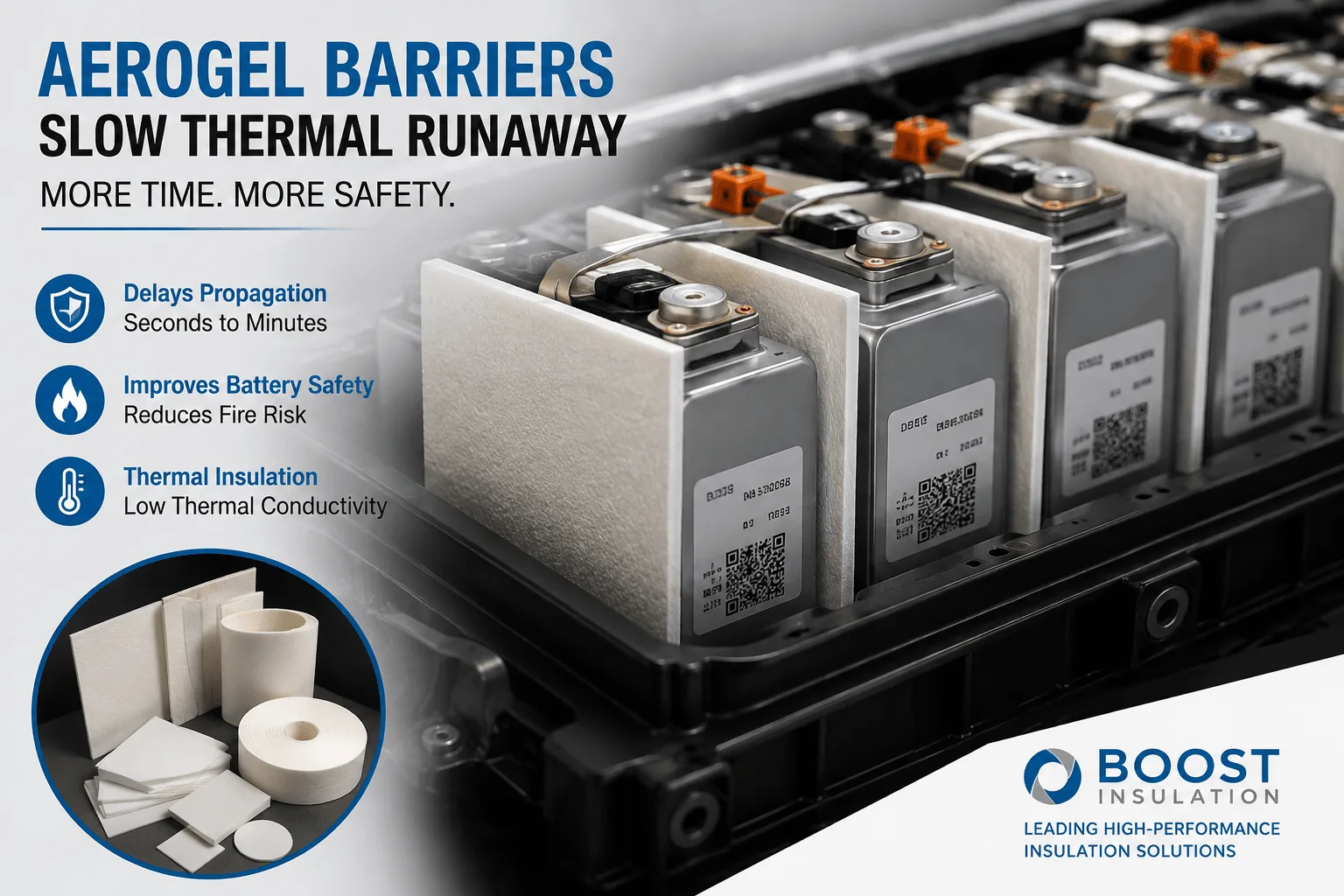
How Much Delay Can an Aerogel Barrier Provide in EV Packs?
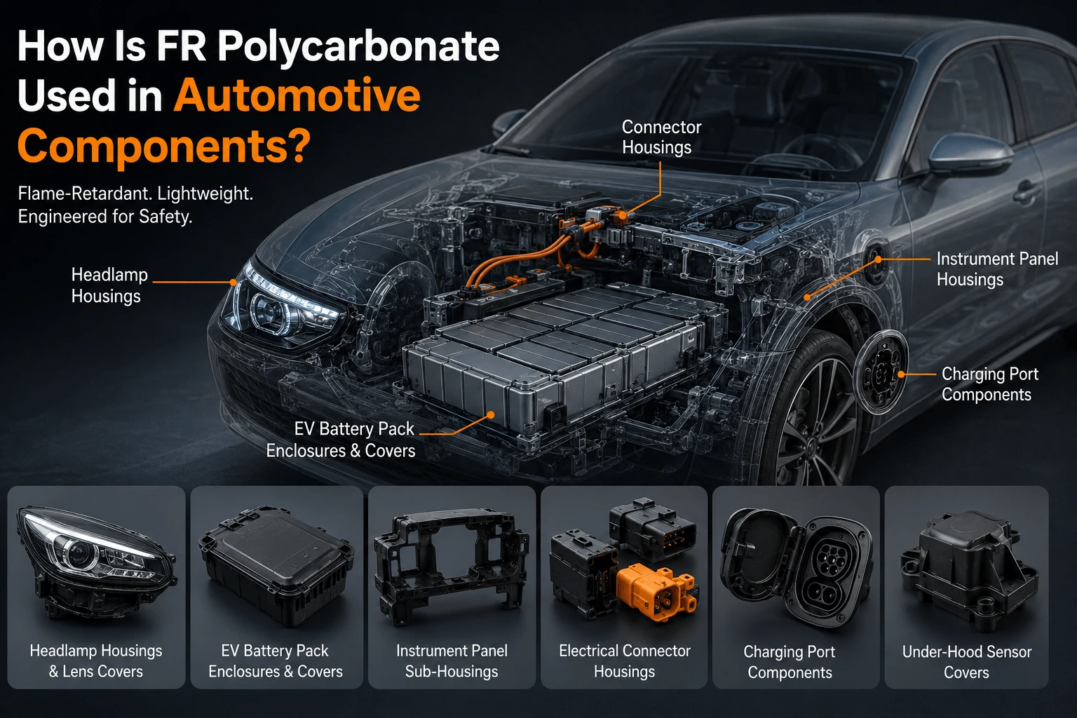
How Is FR Polycarbonate Used in Automotive Components?
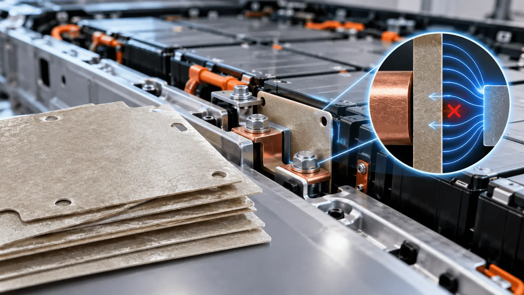
How Does Mica Prevent Dielectric Breakdown in EV Batteries?
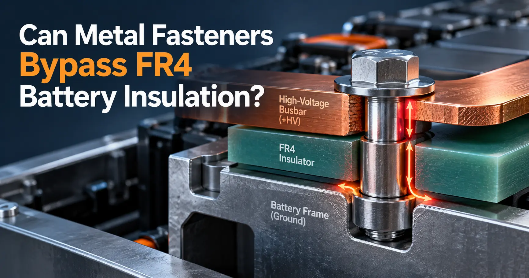
Can Metal Fasteners Bypass FR4 Battery Insulation?
What Insulation Is Inside a Lithium Battery Module?
How to Choose EV Battery Cell Insulation Pads?
 betty wong
