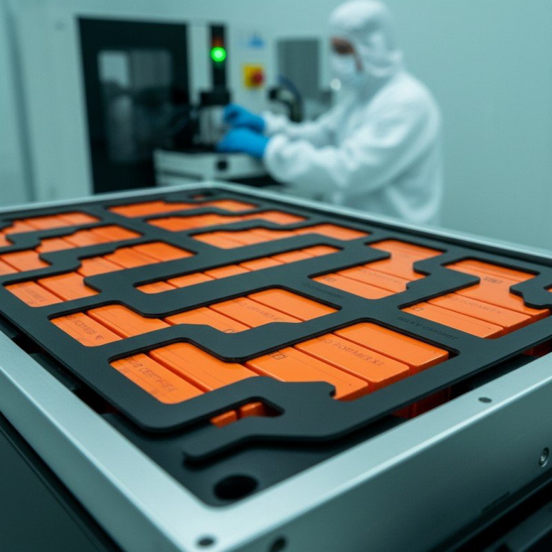
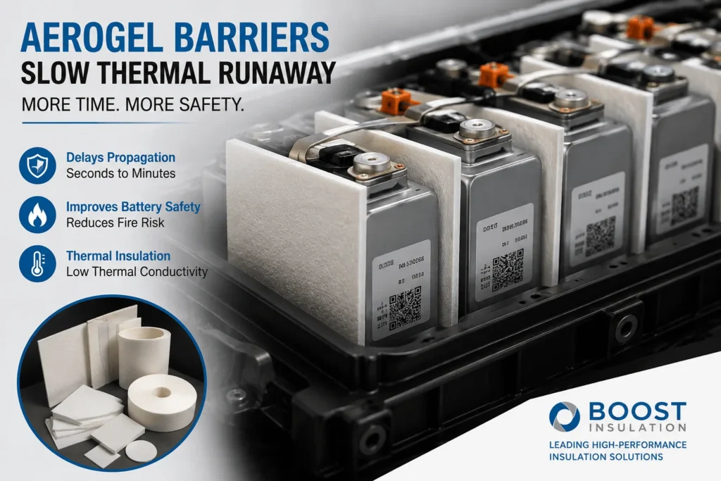
How Much Delay Can an Aerogel Barrier Provide in EV Packs?
Table of Contents
If one cell enters thermal runaway, how many seconds does the next cell have before it follows—and can a thin aerogel barrier turn that interval into enough time for detection, warning, isolation, or evacuation? That is the question battery engineers should ask before choosing a material by thermal conductivity alone, because the useful answer is not printed on a datasheet. It is created by the complete cell, barrier, compression, venting, cooling, busbar, and enclosure design.
| Featured Snippet Answer: An aerogel barrier can add seconds or several minutes of thermal-runaway propagation delay in an EV pack, and a well-designed system may prevent propagation for the required test window. There is no universal delay value: results depend on cell format, chemistry, state of charge, barrier thickness, compression, vent direction, metallic heat paths, trigger method, and the temperature or hazard criterion used. Specify a target delay and validate the finished module or pack—not only the aerogel sheet. |
At a Glance
| Question | Engineering Answer | Validation Requirement |
| How much delay? | Seconds to several minutes; some systems achieve non-propagation. | Test the representative module or pack. |
| What changes it? | Cell energy, SOC, thickness, compression, venting, heat bridges, and test method. | Define worst-case conditions. |
| What should an RFQ state? | A target time, clock definition, protected-cell criterion, and assembled stack-up. | Qualify the finished die-cut part. |
The Direct Engineering Answer: Delay Is a System Result
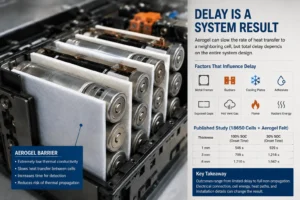
“How much delay?” sounds like a material question, but it is actually a system-performance question. Aerogel has an extremely low solid and gas-phase heat-transfer path, so it can slow the rate at which energy reaches a neighboring cell. However, the next cell can still receive heat through metal frames, busbars, cooling plates, adhesives, exposed gaps, hot vent gas, flame, and radiant energy. The measured delay therefore reflects the weakest route around or through the barrier
published experiments show why a single marketing number is misleading. In one controlled study using 18650 cells and aerogel felt at 1 mm, 3 mm, and 6 mm, increasing thickness progressively delayed thermal-runaway onset in downstream cells. For the farthest cell at 100% state of charge, reported onset times increased from 546 seconds to 709 seconds and then 1,210 seconds as barrier thickness increased. At 30% state of charge, the same downstream-cell onset times were 929, 1,216, and 1,942 seconds. These figures are valuable evidence of the thickness effect, but they are not transferable guarantees for a large prismatic EV module.
Other recent module studies report outcomes ranging from a limited delay to full non-propagation under the tested configuration. One 2026 study reported that an aerogel system prevented propagation in two electrical configurations but produced a 35-second delay in a parallel configuration. The practical lesson is not that aerogel provides “35 seconds” or “20 minutes.” The lesson is that electrical connection, cell energy, heat paths, and installation details can change the result even when the barrier material is similar.
What Does “Propagation Delay” Actually Mean?
Before comparing suppliers, define the start point and end point of the clock. Different laboratories and project teams may report very different “delay” values because they measure different events.
Common start points include heater activation, nail penetration, internal short initiation, first venting, warning-signal activation, or confirmed thermal runaway of the trigger cell. Common end points include a specified temperature at the neighboring cell, rapid temperature-rise onset, neighboring-cell venting, neighboring-cell thermal runaway, flame outside the enclosure, or a hazardous smoke condition.
For supplier specifications, the most useful cell-to-cell metric is usually the interval between confirmed thermal runaway of the initiating cell and confirmed thermal runaway of the adjacent protected cell. Pack approval, however, may use a different safety criterion. UN Regulation No. 100 thermal-propagation provisions use a five-minute warning and hazardous-condition window in relevant approval pathways. That regulatory benchmark should not be confused with a promise that every internal component must independently provide five minutes.
Three outcomes should be separated clearly: propagation is delayed but still occurs; propagation is prevented during the test duration; and external hazards are controlled long enough to meet the vehicle-level requirement. An aerogel barrier can contribute to all three, but only the integrated assembly can demonstrate the final outcome.
How Aerogel Buys Time Between Cells
Aerogel works because its nanoscale porous structure limits several heat-transfer mechanisms simultaneously. The solid silica network contains very little continuous material through which heat can conduct. The pores restrict gas movement and suppress convection. The tortuous internal structure also reduces effective gas conduction, while opacifiers or composite layers can reduce high-temperature radiation.
In a cell-to-cell application, this creates thermal resistance between the hot cell casing and the protected cell. The surface of the neighboring cell heats more slowly, so its internal components take longer to reach the temperatures at which separator shrinkage, electrolyte reactions, cathode decomposition, and self-heating accelerate. The barrier does not “cool” the failing cell. It reduces the rate at which the failure energy is delivered to the next cell.
Thickness normally increases thermal resistance, but usable thickness is the compressed thickness in the assembled module—not the free-state value in the supplier catalog. A nominal 2.0 mm pad compressed to 1.2 mm may behave very differently from a pad that remains at 1.8 mm. Compression can also alter contact area, fiber structure, density, and heat leakage at the edges.
The aerogel layer is therefore best viewed as a time-creation component. The generated time can support sensor detection, BMS warning, contactor opening, active cooling, venting, and occupant response. Whether that time is ten seconds or ten minutes must be measured in the target design.
The Eight Variables That Control the Available Delay
1.Cell chemistry and state of charge: High-energy nickel-rich cells and cells at high state of charge generally produce more severe thermal events than lower-energy or lower-SOC test articles. A barrier that succeeds with one chemistry or SOC cannot be assumed to succeed with another.
2. Cell format and capacity: Heat flow from an 18650 cell differs from a large prismatic or pouch cell. Larger facing surfaces increase the area available for direct conduction and radiation. Large-format cells may also release more energy and direct venting toward specific parts of the module.
3. Barrier thickness and high-temperature stability: Thicker barriers usually increase delay, but only while the material retains structure during exposure. Shrinkage, cracking, melting of encapsulation films, or local erosion can create a rapid heat path.
4. Compression and cell swelling: Pouch and prismatic cells can load the barrier throughout life. Excessive compression can thin the insulation and increase solid contact. Insufficient compression can create gaps, misalignment, or loss of mechanical control.
5. Coverage and edge design: A pad that leaves exposed corners, folded tabs, vent-facing openings, or metal-to-metal bridges may allow heat to bypass the main insulated area. Edge seals must control dust without becoming a thermally conductive frame.
6. Vent and flame direction: Hot particles and jet flames can cross a gap faster than conduction through the aerogel. The barrier geometry must be coordinated with cell vents, exhaust channels, top covers, and flame shields.
7. Metallic heat bridges: Busbars, side plates, end plates, cooling plates, fasteners, and module frames can carry energy around the barrier. A successful design often uses aerogel together with flame-retardant polycarbonate, mica, coated films, or local thermal breaks.
8. Test method and pass criterion: Heater power, trigger duration, nail location, electrical connection, enclosure pressure, airflow, ambient temperature, and sensor location all affect the measured delay. Comparison is valid only when the test conditions are comparable.
How Published Delay Data Should Be Read
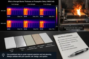
Published test data is most useful for understanding trends, not for copying a headline number into a drawing. The 18650 thickness study cited above demonstrated that 1 mm, 3 mm, and 6 mm aerogel barriers produced progressively later downstream-cell onset. It also showed that the same barrier thickness produced different timing at 30% and 100% SOC. This is direct evidence that barrier thickness is important and that cell condition can be equally important.
A 2024 experimental study of nanofiber aerogel in high-specific-energy modules also treated intercell thermal barriers as an effective propagation-control strategy. Recent work on reinforced and multifunctional aerogel systems has continued to pursue higher mechanical durability, lower radiation transfer, and stable performance under compression. These studies reflect an industry shift from fragile insulation coupons toward engineered laminates that must survive the vehicle lifecycle.
At the same time, current research also warns against oversimplification. Some large-format module studies have found that conventional aerogel alone does not reliably guarantee non-propagation under severe conditions. The best-performing concepts increasingly combine low thermal conductivity with structural reinforcement, flame shielding, controlled venting, phase-change or heat-spreading functions, and careful electrical isolation.
For an EV project, published evidence should support material screening and test-plan design. It should not replace validation of the selected cell, barrier stack-up, compression, electrical configuration, and enclosure.
What Delay Should an EV Project Target?
The correct target begins with the vehicle safety objective, not with the aerogel supplier’s brochure. A project may define one or more of the following goals: prevent adjacent-cell runaway for the complete test duration; create at least five minutes between warning and hazardous external effects; keep the neighboring cell below a specified surface temperature; prevent flame from reaching the pack cover; or limit propagation to one cell or one module.
A five-minute target is commercially important because current UN R100 thermal-propagation requirements and newer amendment work focus on providing a warning interval and preventing specified hazardous conditions during that period. However, a responsible material specification should not simply state “aerogel must provide five minutes.” It should define the trigger, the sensor location, the protected cell, the assembly compression, the test SOC, and the pass/fail condition.
Some architectures may need only enough delay to allow active systems to respond. Other platforms, especially high-energy cell-to-pack designs, may pursue no propagation. For these projects, a thin barrier that adds one minute can still be valuable, but it is not sufficient if the acceptance criterion is non-propagation for an hour-long observation period.
The design team should therefore create a delay budget. Assign the required performance to the complete passive and active safety system: intercell aerogel, structural insulation, vent routing, cooling, sensors, BMS logic, contactors, pack cover, and vehicle warning strategy.
How to Specify an Aerogel Barrier for a Real EV Module
A technically useful request for quotation should contain more than material name and thickness. Include the target cell chemistry, cell dimensions, state-of-charge test condition, normal operating compression, end-of-life swelling allowance, trigger method, required delay, protected-cell temperature limit, vent direction, and available envelope.
Ask for thermal conductivity at relevant temperature and pressure, not only a room-temperature nominal value. Request thickness tolerance, density, compressive stress-strain data, compression set, recovery, dielectric strength if electrical isolation is required, flame behavior at the specified thickness, high-temperature shrinkage, dust-control method, and evidence for the finished laminate.
The finished part may contain an aerogel core, carrier felt, PET or PI encapsulation film, pressure-sensitive adhesive, release liner, reinforcement, printed identification, and pull tabs. Each layer changes thickness, flame behavior, mechanical durability, edge leakage, assembly efficiency, and cost. The qualification unit should therefore be the converted part—not only the core aerogel.
Define critical dimensions on the drawing: overall profile, vent clearances, edge-seal width, adhesive keep-out zones, cutouts, locating features, pull-tab dimensions, liner split, burr or loose-fiber limits, flatness, and packaging orientation. These details are often the difference between a promising material and a stable high-volume assembly process.
Why Aerogel Is Often Combined With PC, Silicone Foam, or Mica
No single material provides every function inside an EV pack. Aerogel is selected primarily for high thermal resistance in limited thickness. Flame-retardant polycarbonate insulation sheets add puncture resistance, dielectric separation, large-area structural stability, and clean assembly surfaces. Silicone foam manages gap variation, preload, vibration, and cell swelling. Mica provides a rigid high-temperature flame and electrical barrier in locations exposed to direct jetting or pack-cover fire.
A common hybrid stack uses aerogel as the principal intercell thermal resistor, silicone foam or a compliant layer to manage pressure, and a thin PC or film layer to protect the surface and maintain electrical isolation. At module boundaries, aerogel may be paired with mica or a rigid flame shield. The right order depends on which side faces the cell, where venting occurs, and how the stack is compressed.
Hybrid structures must be evaluated carefully. Adding a high-conductivity adhesive across the full face can reduce thermal resistance. A rigid skin may protect the aerogel but create edge bridges. A soft foam may improve contact but compress the aerogel below its intended operating thickness. The stack-up should be optimized as a system and tested in its assembled condition.
Application Differences by Cell Format
For prismatic cells, the broad side faces create a large heat-transfer area. Aerogel pads normally require near-full active-area coverage, controlled edge sealing, and predictable compression. Cutouts around terminals and vents must avoid creating short paths to the adjacent cell.
For pouch cells, the barrier also participates in pressure and swelling management. The stack must retain insulation while cycling through changes in thickness. Local wrinkles, hard adhesive steps, or poorly positioned tabs can create nonuniform pressure on the pouch.
For cylindrical cells, the contact geometry is different. Barriers may be placed between rows, groups, or modules rather than as full rectangular intercell pads. Hot gas paths through the spaces between cylinders can dominate, so row barriers, flame shields, and vent-direction control may be as important as the aerogel’s conductivity.
Cell-to-pack and cell-to-chassis architectures reduce module boundaries and may increase the distance over which a single event can spread. They can also use structural members and cooling plates as heat paths. These platforms require early thermal mapping and coordinated use of cell barriers, structural dielectric sheets, under-lid fire protection, and vent management.
Die-Cutting and Lamination: Where Delay Is Won or Lost
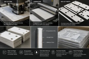
Aerogel performance can be degraded during conversion. Excessive crushing at the cut edge, exposed powder, broken encapsulation, adhesive squeeze-out, dimensional drift, or warped parts can reduce effective coverage and create assembly defects. High-quality die cutting must therefore control both geometry and material condition.
For prototypes, digital cutting or flatbed tooling can support rapid design changes. For volume production, rotary or progressive die cutting may improve consistency and cost when the laminate and feature geometry are suitable. Tool clearance, blade condition, support liner, cutting direction, web tension, and dust extraction must be validated for the selected composite.
Encapsulation can improve handling and reduce particulate release, but the film should survive forming, compression, electrolyte exposure, and the project’s heat and flame conditions. Adhesive should be placed only where needed for assembly. Zoned adhesive or perimeter fixation can preserve more thermal resistance than a full-face adhesive layer, depending on the design.
Incoming inspection should verify core material, thickness, density, and certification. In-process controls should monitor profile dimensions, edge-seal continuity, adhesive registration, liner release, contamination, and part orientation. Final packaging must prevent crushing, moisture exposure, and deformation during international shipment.
A Five-Level Validation Plan
Level 1: Material and laminate screening. Measure thickness, density, thermal conductivity, high-temperature dimensional stability, compression behavior, dielectric properties, flame response, adhesive peel, and contamination risk.
Level 2: Thermal coupon testing. Test the complete stack-up under representative compression using a hot plate, heat-flux source, or heater geometry that approximates the cell interface. Compare cold-side temperature, time to thresholds, and post-test integrity.
Level 3: Single-interface or two-cell testing. Place the converted barrier between representative cells or cell simulators. Evaluate direct conduction, edge leakage, vent exposure, mechanical preload, and temperature at multiple locations.
Level 4: Module propagation testing. Trigger a selected cell using the project-defined method. Record trigger-cell runaway, neighboring-cell temperatures, venting, flame, voltage, gas, and propagation timing. Repeat across production-relevant tolerances and worst-case SOC.
Level 5: Pack and vehicle validation. Confirm the complete warning strategy, external hazard criteria, venting, enclosure response, electrical isolation, and post-event safety. Only this level can substantiate pack-level compliance or a vehicle safety claim.
Testing should include aged parts when the barrier also carries compression or adhesive functions. Heat aging, humidity, vibration, compression cycling, electrolyte exposure, and storage can change the installed condition long before a thermal event occurs.
Common Mistakes That Produce Unrealistic Delay Claims
Using a datasheet conductivity value to calculate a guaranteed propagation time is the most common error. Thermal runaway is transient, multidirectional, and includes radiation, hot gas, flame, and metallic conduction. A one-dimensional steady-state calculation can support early screening but cannot predict the complete event.
Another error is reporting time from heater activation rather than from trigger-cell thermal runaway. A long preheating stage can make the apparent delay look larger without improving intercell protection. Test reports should identify the exact clock definition.
Teams also overestimate performance when they test an uncompressed coupon while the production module heavily compresses the pad. They may ignore vent jets, use lower SOC, omit busbars, test a smaller cell, or apply a trigger that differs from the homologation plan.
Finally, buyers sometimes qualify a branded aerogel core and later change the film, adhesive, thickness, edge seal, or converter. Those changes can alter the final part. Change control should cover the complete bill of materials and conversion process.
Industry Insight: The Market Is Moving From Material Claims to Time Budgets
EV battery safety programs are increasingly asking suppliers for measured propagation delay, cold-side temperature curves, compression-dependent data, and evidence from realistic assemblies. “Low thermal conductivity” remains important, but it is no longer enough to win a technical nomination.
The next generation of barriers is becoming multi functional. Development programs are combining aerogel with reinforcement, radiation-blocking additives, compliant pressure-management layers, dielectric skins, phase-change components, or directed heat-spreading structures. The objective is to preserve insulation during normal vehicle life and control the complex energy release during failure.
This shift favors converters that can participate in DFM, create controlled multilayer laminates, produce dimensionally stable die-cut parts, maintain clean processes, and support rapid prototype iterations. It also changes the buying conversation: customers are not purchasing square meters of aerogel. They are purchasing validated seconds, stable assembly, and traceable production parts.
How Boost Insulation Supports Aerogel Barrier Development
Boost Insulation supports custom EV battery insulation projects with aerogel, flame-retardant polycarbonate, silicone foam, mica, films, adhesives, and precision die-cut conversion. This allows engineering teams to evaluate a complete functional stack rather than sourcing every layer independently.
Support can include material selection, laminate design, adhesive zoning, edge encapsulation, pull-tab and liner design, tolerance review, prototype cutting, inspection planning, and volume-production DFM. For a useful review, send the cell or module drawing, target thickness, compression range, vent location, material restrictions, required flame and dielectric properties, delay target, and planned validation method.
A credible quotation should identify assumptions and open technical risks. A prototype should be treated as the first step in verification—not as proof of pack compliance.
| Need a defensible propagation-delay target?
Send Boost Insulation your cell or module drawing, installed thickness, compression range, vent direction, target delay, and validation method. The engineering team can review the stack-up, recommend aerogel, PC, silicone foam, mica, film, and adhesive options, and prepare a prototype quotation. |
Frequently Asked Questions
Can an aerogel barrier guarantee five minutes of delay?
No. A five-minute result can only be claimed for a defined, tested assembly. The same material can produce a different delay when cell energy, thickness, compression, venting, busbars, trigger method, or pass criterion changes.
Is a thicker aerogel barrier always better?
Thickness normally increases thermal resistance and can increase delay, but packaging space, compression, swelling, cost, and edge heat paths may limit the benefit. The optimal thickness is the minimum validated thickness that meets the system target with margin.
What is a realistic aerogel delay number for an RFQ?
Use a project-specific target such as “no adjacent-cell runaway for at least 300 seconds after trigger-cell runaway” or “protected-cell surface remains below the defined threshold for 300 seconds.” Avoid requesting a generic material-level delay.
Can aerogel completely prevent propagation?
Yes, some tested systems have achieved non-propagation, but other configurations only gain limited time. Non-propagation is an assembly result and must be confirmed in the representative module and pack.
Does low thermal conductivity predict the delay?
It helps rank materials, but it does not capture compression, radiation, jet flames, vent gas, metal bridges, adhesive layers, or cell energy. It is one input to the design, not the final answer.
Should the adhesive cover the full aerogel surface?
Not automatically. Full-face adhesive may simplify assembly but can change thermal resistance and compression. Zoned, perimeter, or selective adhesive should be evaluated against handling and thermal requirements.
What information should be sent for a prototype?
Provide a 2D drawing, cell format, barrier location, target and installed thickness, compression range, vent direction, adhesive areas, flame and dielectric requirements, delay target, and expected annual volume.
How should suppliers be compared?
Compare the same finished-part stack under the same compression and test method. Review material traceability, conversion capability, edge quality, particulate control, change management, inspection data, prototype speed, and validation support.
Technical References
- United Nations Economic Commission for Europe (UNECE). UN Regulation No. 100, Revision 3, and subsequent 05-series thermal-propagation amendment documents. Source
- Liu, Q., Zhu, Q., and Zhu, W. “Influence of Aerogel Felt with Different Thickness on Thermal Runaway Propagation of 18650 Lithium-ion Battery.” Electrochemistry, 2022. Source
- Wong, S. K. et al. “Mitigating Thermal Runaway Propagation in High Specific Energy Lithium-Ion Battery Modules Using Nanofiber Aerogel.” Energy, 2024. Source
- Chen, M. et al. “Incorporation of Aerogel and Encapsulating Phase Change Materials for Thermal-Runaway Propagation Control.” Energy, 2025. Source
- Chen, Y. et al. “Towards Enhanced Battery Thermal Safety: A Lightweight Aerogel System.” Gels, 2026. Source
- Boost Insulation. EV battery insulation, aerogel conversion, and thermal-management capabilities. Source
Related Posts:
Why Do EV Battery Packs Need Aerogel Insulation Today?
What Are EV Battery Module Solutions and How Do They Work?
Can a Mica Insulation Sheet Work Between Battery Cells?
How Do You Choose a Flame Retardant PC Supplier?

What Is ESS Energy Storage Solution & How It Works?
Why Does EV Battery Insulation Need UL94 V-0?
 betty wong