Can Aerogel Stop Thermal Runaway Propagation in EV Packs?
Table of Contents
If one cell enters thermal runaway, can a thin aerogel pad really keep the next cell below its own runaway threshold? That question matters more than any brochure conductivity value, because the answer depends on the complete heat path – cell spacing, barrier compression, vent direction, metal bridges, state of charge, and the way the finished part is converted and installed.
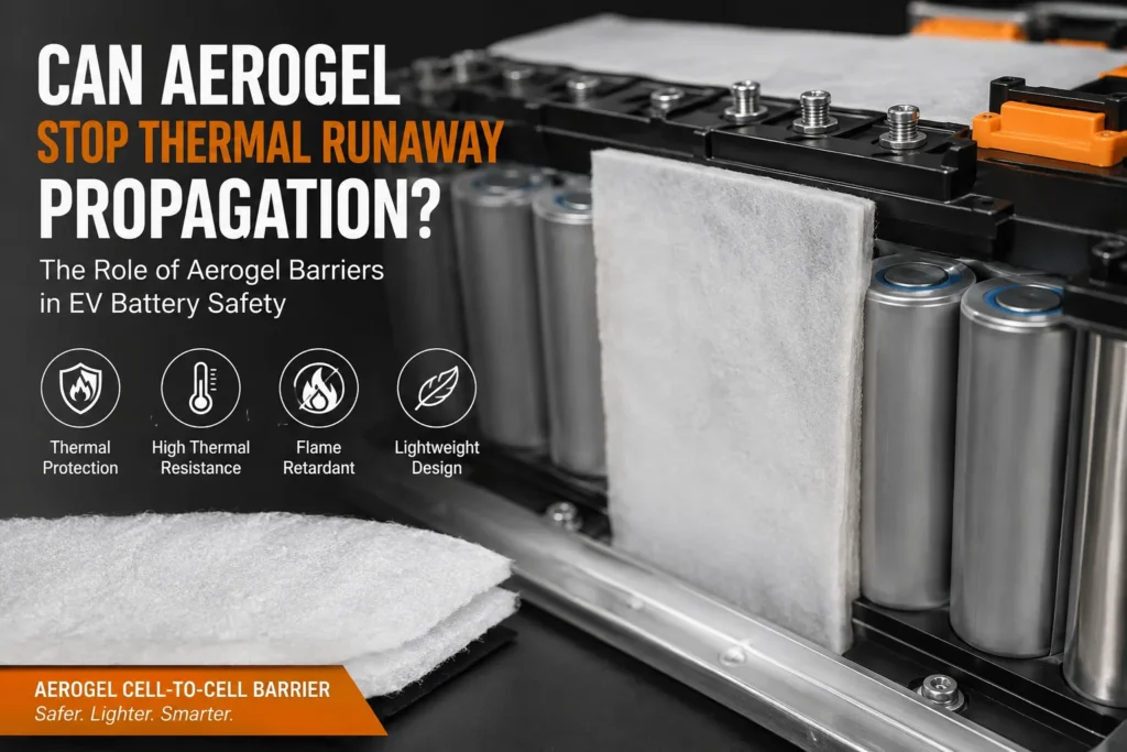
Aerogel can stop thermal runaway propagation in some EV battery modules, but it cannot guarantee propagation prevention by itself. A properly selected and installed aerogel barrier slows conductive, convective, and radiant heat transfer so the adjacent cell may remain below its critical trigger condition. Whether propagation is stopped or only delayed depends on aerogel thickness, high-temperature integrity, compression, edge coverage, vent-gas exposure, cell chemistry, state of charge, cooling, structural heat bridges, and module geometry. The final cell, module, and pack design must be validated under representative abuse conditions.
| Direct engineering answer: Treat aerogel as a propagation-control component, not as a stand-alone certification. It can be decisive when the thermal energy reaching the next cell is reduced below that cell’s runaway threshold for the required time, but the only defensible claim comes from testing the final installed design. |
Can Aerogel Stop Propagation? The Practical Decision Matrix
| Design condition | Likely outcome | Why | Engineering action |
| Continuous barrier, adequate thickness, controlled compression | Can stop or materially delay propagation | Heat flux to the next cell is reduced across the full interface | Validate at representative SOC, spacing, preload, and trigger method |
| Thin or over-compressed aerogel with no margin | Delay may be limited | Effective thermal resistance falls and local hot spots dominate | Test conductivity and thickness after assembly compression |
| Direct vent jet or flame bypasses the pad | Propagation may still occur | Hot gases and particles route around the low-conductivity layer | Add vent control, top barriers, mica/ceramic shields, and sealed edges |
| Metal frame, busbar, or cooling plate bridges cells | Aerogel alone is insufficient | Heat travels through a parallel high-conductivity path | Break or redirect structural heat bridges and validate full stack-up |
| Hybrid barrier plus active cooling and controlled venting | Best probability of containment | Multiple mechanisms reduce heat, flame, pressure, and electrical risk | Treat the pack as a system and test all safety functions together |
What Does “Stop Thermal Runaway Propagation” Actually Mean?
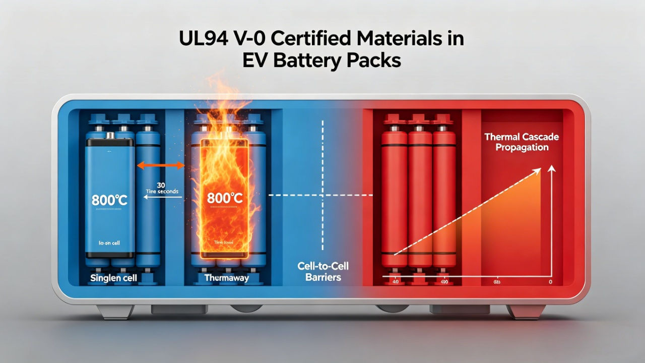
Thermal runaway and thermal runaway propagation are different events. Thermal runaway is the uncontrollable self-heating of one cell after an initiating failure. Propagation is the subsequent triggering of one or more neighboring cells by heat, flame, hot gas, electrical interaction, or mechanical damage from the first event.
In engineering discussions, “stop propagation” may refer to three different outcomes: no neighboring cell enters thermal runaway; propagation is delayed long enough to meet a defined warning or egress objective; or propagation is confined to a limited group of cells without creating a hazardous condition outside the pack. These are not interchangeable claims. A material may improve all three outcomes, but each must be defined and measured at the relevant assembly level.
This distinction is important for purchasing. A supplier can provide thermal conductivity, maximum-use temperature, flammability data, thickness tolerance, or dielectric data for a sheet. None of those values independently proves that an EV pack will contain a cell failure. Propagation is an energy-balance and system-integration problem.
Why Thermal Runaway Propagation Is Difficult to Block
A failing lithium-ion cell can release heat through several paths at the same time. Direct surface-to-surface conduction heats the adjacent cell casing. Radiant heat crosses small air gaps. Hot gases and flame may travel through a vent channel. Busbars, module frames, fasteners, cooling plates, and compression hardware can carry heat around an insulation pad. Ejected particles may damage polymer films or ignite nearby materials.
The initiating cell also changes the local mechanics. Pouch and prismatic cells can swell, push against the barrier, or open a gap elsewhere in the stack. Adhesive may soften. A thin encapsulation film may shrink. A vent event can displace a poorly retained part. Therefore, the barrier is not tested only by temperature; it is tested by pressure, movement, flame, gas flow, vibration history, and manufacturing variation.
Cell condition changes the challenge. Higher state of charge generally increases the available reaction energy, while aged cells may display different heat-release and gas-generation behavior from new cells. Chemistry, cell format, capacity, triggering method, orientation, and spacing all influence whether the next cell reaches its critical temperature. This is why a thickness that works in one module cannot be copied blindly into another.
How Aerogel Reduces the Energy Reaching the Next Cell
Battery aerogel insulation usually uses a silica-based nano porous network reinforced with fibers or carried in a flexible composite. The extremely small pores restrict gas-phase heat transport, and the sparse solid network limits solid conduction. The result is high thermal resistance at relatively low thickness and mass – a valuable combination in tightly packaged EV modules.
Aerogel primarily reduces conductive heat flow across the cell-to-cell interface. It also reduces gas movement inside the barrier and can lower the net radiant energy reaching the adjacent cell, depending on formulation, reinforcement, surface layers, and temperature. The barrier does not remove heat from the pack; it increases the time required for heat to cross the interface.
That time shift is the central safety benefit. If the neighboring cell loses heat to its cooling path faster than it gains heat through the barrier, its temperature can stabilize below the onset of self-heating. If the incoming energy remains too high, aerogel may still delay the event. The difference between prevention and delay is determined by the complete module energy balance, not by the word “aerogel” on a material specification.
Published experiments demonstrate both possibilities. Some high-performance aerogel architectures have prevented cascade propagation in the tested module, while other studies show a strong dependence on thickness, density, cell type, state of charge, and hybrid construction. The correct conclusion is conditional: aerogel can be highly effective, but performance belongs to the tested material-and-module combination.
When Aerogel Is Most Likely to Stop Propagation
Aerogel has the best chance of preventing propagation when the dominant path is broad-area heat transfer between adjacent cell faces and the barrier covers that path continuously. Large prismatic and pouch-cell interfaces are common examples. The effective layer must remain in position and retain enough thickness during normal assembly preload, swelling, vibration, and abuse.
The module also needs a controlled path for vent gases and flame. If a cell vents upward, the design should prevent the jet from striking the next cell, busbar, sensing circuit, or polymer component. A cell-face aerogel pad cannot solve a top-vent fire path that bypasses the interface. Top shields, mica or ceramic layers, directed vents, spacing, and enclosure features may be required.
Active cooling can improve the margin when it remains available. A cooling plate or liquid loop can remove heat from neighboring cells while aerogel reduces incoming heat. However, designers should also assess scenarios in which pumps, valves, sensors, or electrical controls are unavailable. The passive barrier must be evaluated against the safety objective assigned to it.
Consistent manufacturing is another enabling condition. Correct dimensions, no missing corners, controlled thickness, intact encapsulation, and repeatable adhesive placement prevent local short circuits in the thermal resistance. A barrier that works in a laboratory but has variable coverage or compression in production will not provide a stable safety margin.
When Aerogel Cannot Be Expected to Work Alone
Aerogel is not a universal fire wall. A direct flame jet, high-velocity vent gas, or molten particle stream may overwhelm or bypass a thin cell-face pad. A conductive metal bridge can carry heat around it. A gap at a tab, corner, cooling channel, or fastener can concentrate heat into a small unprotected area. An edge that opens after repeated swelling can create a new path late in vehicle life.
Over-compression is a common hidden failure mode. Designers may specify nominal thickness, then clamp the stack until the aerogel is substantially thinner. The installed thermal resistance can be different from the flat-sheet data. Compression can also damage the pore structure, create permanent set, or transfer load unevenly to the cell. Thickness and conductivity should therefore be characterized in the compressed condition that the module actually uses.
The cover film and adhesive can also control failure. PET or other encapsulation may improve handling and reduce dust, but the film can shrink, soften, burn, or create a heat bridge depending on its grade and thickness. Adhesive can help retain the part during assembly, yet it may introduce combustible mass or lose bond strength at high temperature. The completed laminate must be assessed as a system.
Finally, no passive barrier corrects an unsafe electrical or mechanical architecture. Internal shorts, busbar faults, inadequate fuse coordination, poor venting, crushing, coolant leakage, and enclosure weakness require their own controls. Aerogel is one layer of defense within a broader thermal, electrical, mechanical, detection, and containment strategy.

The Engineering Variables That Decide the Result
1. Cell Chemistry, Capacity, State of Charge, and Aging
NMC, NCA, LFP, and other cell systems do not release identical heat or gas under abuse. Cell capacity and geometry affect the total energy and surface heat flux. State of charge changes severity, while aging can change internal resistance, gas generation, and failure timing. Barrier testing should use representative production cells at relevant SOC and, where required, aged conditions.
2. Barrier Thickness and Installed Compression
Increasing thickness normally increases through-plane thermal resistance, but the benefit is not always linear at extreme temperature because radiation, contact resistance, gas flow, and material changes become important. Engineers should specify nominal thickness, tolerance, compression range, and minimum retained thickness after assembly and life-cycle swelling.
3. Coverage, Edge Geometry, and Bypass Paths
The barrier should cover the true heat-transfer area, including corners and regions near tabs when those regions are exposed. Cutouts must be justified. Narrow edge seals and adhesive zones should not create continuous conductive routes. Metal hardware, liquid-cooling plates, side rails, and compression plates should be included in the thermal model and physical test.
4. High-Temperature Integrity and Mechanical Retention
Useful barriers remain coherent long enough to perform their safety function. Reinforcement, encapsulation, tensile strength, puncture resistance, tear resistance, dust control, and dimensional stability affect whether the part survives handling and an abuse event. The design should account for vent pressure, flame exposure, vibration, impact, and assembly abrasion.
5. Electrical Insulation and Flame Behavior
Aerogel composites may contribute electrical isolation, but dielectric requirements should be specified separately from thermal requirements. Verify withstand voltage, insulation resistance, tracking risk, edge quality, contamination, and interaction with adjacent conductors. A UL 94 rating is useful for material flammability screening, but UL itself describes UL 94 as a small-scale material test; it is not proof of pack-level thermal runaway containment.
6. Cooling, Venting, Detection, and Pack Structure
Aerogel performs best when coordinated with the pack’s other safety functions. Cooling removes heat, vent routing directs gases, sensors detect abnormal conditions, electrical protection interrupts current, and the enclosure limits occupant exposure. A robust design assigns a clear safety function to each component and validates the sequence of events, including degraded or failed active systems.
How the Answer Changes by Cell Format
| Cell format | Primary propagation paths | Aerogel role | Design cautions |
| Prismatic | Large side-face conduction, top venting, frame bridges | Full-face inter-cell pad with controlled compression | Protect vent path, tabs, edges, cooling plate, and swelling allowance |
| Pouch | Broad face conduction, stack compression, pouch swelling | Thin flexible barrier integrated with compression management | Avoid wrinkles, puncture, edge gaps, and excessive local pressure |
| Cylindrical | Point/line contacts, air channels, flame and gas flow | Die-cut rings, wraps, array partitions, or group barriers | Flow paths around cells can bypass flat insulation; geometry is critical |
| Cell-to-pack / CTC | Long-range structural paths and fewer module walls | Localized cell barriers plus regional and enclosure barriers | Coordinate with vehicle structure, cooling, serviceability, and crash load paths |
Why Hybrid Barrier Systems Often Outperform a Single Material
A modern cell-to-cell barrier may need low thermal conductivity, electrical isolation, mechanical spacing, compression control, flame resistance, puncture resistance, clean assembly, and tolerance compensation. One material rarely optimizes every function, so hybrid stacks are increasingly common.
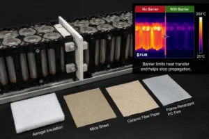
Aerogel provides the primary thermal-resistance layer. Flame-retardant polycarbonate can add dielectric isolation, puncture resistance, dimensional stability, and a clean structural surface. Silicone foam can absorb tolerance, maintain contact, manage cell swelling, reduce vibration, and help retain the barrier. Mica or ceramic layers can strengthen resistance to direct flame, radiant heat, and particle impact in high-exposure zones.
The best sequence depends on the heat direction and assembly mechanics. A rigid PC layer placed incorrectly can bridge heat or concentrate load. A soft foam can compress the aerogel beyond its intended range. An adhesive can simplify installation but reduce high-temperature durability. The stack should be designed as a functional architecture, not assembled from individually attractive datasheets.
Why Precision Die-Cutting and Lamination Affect Thermal Safety
Thermal barrier performance can be lost during conversion. A die-cut notch may expose the next cell. Dust or debris may reduce dielectric safety. A laminated film may wrinkle and create an air channel. Thickness may vary at adhesive overlaps. Misaligned release liners or missing pull tabs can cause operators to bend, tear, or contaminate the part during assembly.
For cell-to-cell aerogel components, the drawing should control finished thickness, outline tolerance, critical coverage zones, vent clearances, corner radii, edge-seal width, adhesive keep-out areas, liner splits, pull tabs, part orientation, and cleanliness. The drawing should also distinguish dimensions that affect safety performance from dimensions that only affect handling.
A capable converter should review the drawing before tooling. DFM may identify an unsupported narrow feature, a cut line too close to the aerogel core, a liner that cannot be removed automatically, or a tolerance that forces unnecessary scrap. Early conversion input reduces both technical risk and landed cost.
A Validation Ladder for Defensible Propagation Claims
Start with material screening, but do not end there. The validation plan should progressively reproduce the installed part and the final energy paths.
Level 1 – Material and laminate coupons: measure thickness, density, thermal conductivity or diffusivity, compression behavior, dielectric strength, flame behavior, peel strength, and aging. Test the finished laminate where films and adhesives are part of the design.
Level 2 – Component heat-flux tests: expose the converted barrier to representative heat flux, temperature, pressure, and duration. Measure cold-side temperature, structural integrity, shrinkage, delamination, and edge performance.
Level 3 – Cell-pair or small-array tests: use the intended cell format, spacing, preload, orientation, SOC, vent direction, and trigger method. Instrument the trigger cell, adjacent cells, barrier surfaces, cooling plate, vent path, and enclosure features.
Level 4 – Module propagation tests: evaluate realistic busbars, frames, cooling, sensing, venting, compression, and manufacturing tolerances. Confirm whether the safety objective is no propagation, limited propagation, or a defined delay.
Level 5 – Pack and vehicle-level validation: demonstrate the required occupant and system outcomes under the applicable regulation, OEM specification, and abuse matrix. International rules such as UN Regulation No. 100 evaluate REESS and vehicle-level safety outcomes; the direction of recent amendments is toward more explicit and robust thermal-propagation assessment.
Industry Insight: The Market Is Moving From “Good Material” to “Proven Installed System”
As cell-to-pack and cell-to-chassis designs remove modules and inactive structure, designers gain energy density but lose some natural compartmentalization. The barrier becomes more integrated with cooling plates, structural adhesives, electrical isolation, and the vehicle floor. This increases the importance of full-path analysis and makes converted-part quality more visible in the safety result.
At the same time, fast charging, higher pack voltage, reduced cell spacing, and longer warranty expectations expand the operating and aging envelope. The industry response is not simply to use thicker insulation everywhere. Weight, cost, cooling efficiency, and packaging space limit that approach. Engineers increasingly place higher-performance barriers only where modeling and testing show the highest propagation risk.
The commercial implication is clear: buyers are moving beyond requests for a generic aerogel sheet. High-quality RFQs specify the cell format, thermal objective, installed compression, laminate structure, flame and dielectric requirements, critical geometry, validation plan, annual volume, and traceability needs. Suppliers that can co-engineer the converted component are more valuable than suppliers that only quote raw material by area.
What Should an RFQ for a Cell-to-Cell Aerogel Barrier Include?
- Cell chemistry, format, capacity, dimensions, orientation, and state-of-charge test condition.
- Cell spacing, module compression method, preload range, swelling allowance, and end-of-life assumptions.
- Propagation objective: no propagation, maximum number of cells, target delay, or occupant-protection requirement.
- Trigger method and validation standard or OEM test specification.
- Available thickness, minimum retained thickness, mass target, and dimensional envelope.
- Aerogel grade or required conductivity, density, temperature stability, mechanical strength, and dust limits.
- Protective film, adhesive, release liner, edge seal, pull tab, marking, and orientation requirements.
- Electrical requirements: dielectric withstand voltage, insulation resistance, creepage, and cleanliness.
- Critical cutouts, vent clearances, busbar areas, cooling interfaces, and structural heat bridges.
- Prototype quantity, annual volume, PPAP level, traceability, packaging, and delivery location.
How Boost Insulation Supports Aerogel Thermal Barriers
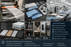
Boost Insulation positions its service around material selection, DFM, lamination, precision die-cutting, rapid prototyping, clean production, testing, and high-volume traceability. For an aerogel propagation project, that means the discussion can include the aerogel core, protective films, adhesive, edge sealing, PC electrical barriers, silicone foam compression layers, mica protection, and the final die-cut geometry rather than treating each layer as a separate purchasing problem.
The company states that it supports IATF 16949 and ISO 9001 workflows, APQP and PPAP documentation, controlled cleanroom production, in-house tooling, sub-millimeter precision, 48-hour prototyping, and batch testing such as dielectric withstand voltage, peel strength, and high-temperature aging. These capabilities are relevant to moving a thermal-barrier design from a drawing to a repeatable part.
For an efficient review, send the cell and module layout, CAD or PDF drawing, target thickness, compression window, material stack, expected heat or propagation test, electrical requirements, flame requirement, annual volume, and sample schedule. The engineering team can then identify manufacturability risks and propose a prototype route.
Frequently Asked Questions
Can aerogel guarantee that no neighboring EV cell will enter thermal runaway?
No. Aerogel can reduce the energy reaching adjacent cells and may stop propagation in a validated design, but a guarantee requires evidence from the final cell, module, and pack configuration.
Is thicker aerogel always better?
Greater thickness usually improves thermal resistance, but packaging, compression, weight, venting, cooling, and edge geometry can dominate the outcome. The correct thickness is the minimum validated thickness with adequate manufacturing margin.
Can UL94 V-0 prove thermal runaway propagation resistance?
No. UL94 V-0 is a small-scale flammability classification. It is useful for screening material behavior after ignition, but it does not reproduce cell heat release, vent gas, module geometry, or pack-level propagation.
Does aerogel replace the liquid-cooling system?
No. Aerogel restricts heat transfer; cooling removes heat. The two functions are complementary, especially when designers need both normal-operation temperature control and abuse-event protection.
Should aerogel be laminated with PET film?
Encapsulation can improve cleanliness, handling, die-cutting, and assembly. The film and adhesive must be selected for the temperature, flame, dielectric, shrinkage, and aging requirements of the finished part.
Why combine aerogel with PC insulation or silicone foam?
PC can provide a robust dielectric and puncture-resistant layer, while silicone foam can manage tolerance, vibration, and swelling. The hybrid stack can address more functions than aerogel alone, provided it is validated under compression and heat exposure.
What is the fastest way to obtain a useful quotation?
Send a drawing or pack layout together with cell format, thickness and compression limits, laminate requirements, test target, prototype quantity, and annual volume. That information enables a DFM review instead of a generic material price.
Turn a Material Question Into a Testable Barrier Design
Aerogel can stop thermal runaway propagation when the installed barrier reduces every important heat path below the threshold that triggers the next cell. It can also fail when heat bypasses the pad, the layer is over-compressed, the vent path is uncontrolled, or the finished laminate has not been validated. The engineering task is therefore to connect the material, geometry, conversion process, module mechanics, cooling, venting, and test method into one evidence-based design.
| Project CTA: Upload your CAD or PDF drawing to Boost Insulation for a manufacturability review. Include your cell format, target thickness, compression range, dielectric and flame requirements, prototype quantity, and propagation-test objective to receive a focused material and conversion proposal. |
Recommended Internal Links for Publication
- Aerogel Insulation
- EV Battery Module Insulation
- Thermal Management Solution
- Energy Storage Solution
- Contact / Upload Design
Technical References and Source Notes
- UNECE, UN Regulation No. 100 Rev.3, electric power train and rechargeable electrical energy storage system safety requirements. Source
- UNECE, 05 series of amendments to UN Regulation No. 100 – improved thermal propagation requirements adopted in 2025 with later transitional dates. Source
- Li et al., “Large-scale assembly of isotropic nanofiber aerogels for high-capacity battery thermal runaway protection,” Nature Communications, 2023. Source
- Chen et al., study of flame-retardant phase-change materials and aerogel felt for thermal runaway propagation inhibition in pouch battery modules, Applied Energy, 2024. Source
- Huang et al., glass-fiber-reinforced silica aerogel composite as an internal thermal barrier for lithium-ion batteries, Energy, 2025. Source
- UL Solutions, UL 94 combustion and small-scale plastics flammability test information. Source
- Boost Insulation, aerogel insulation, EV battery insulation, thermal management, and manufacturing capability pages. Source
Related Posts:
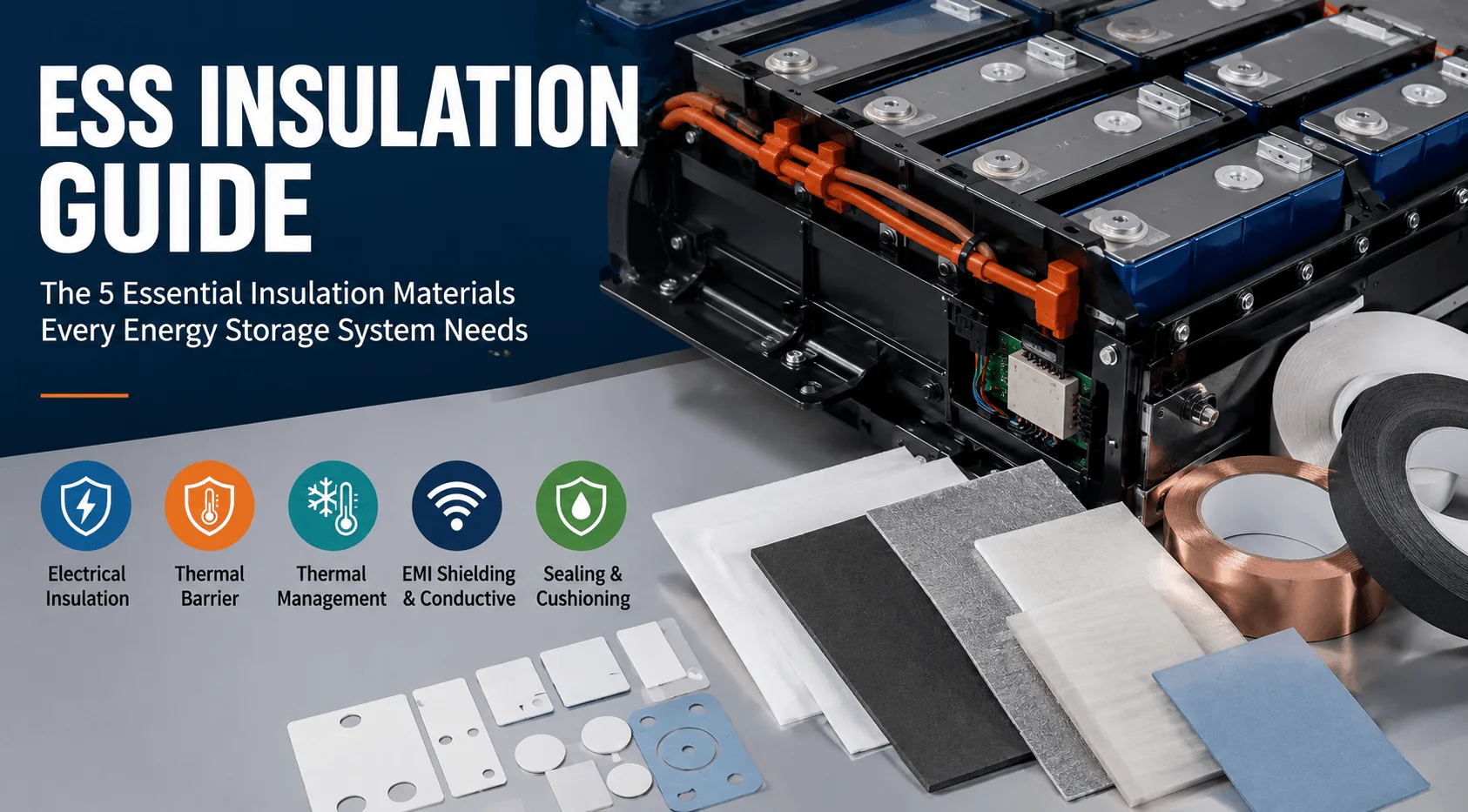
What Insulation Does an Energy Storage System Need?
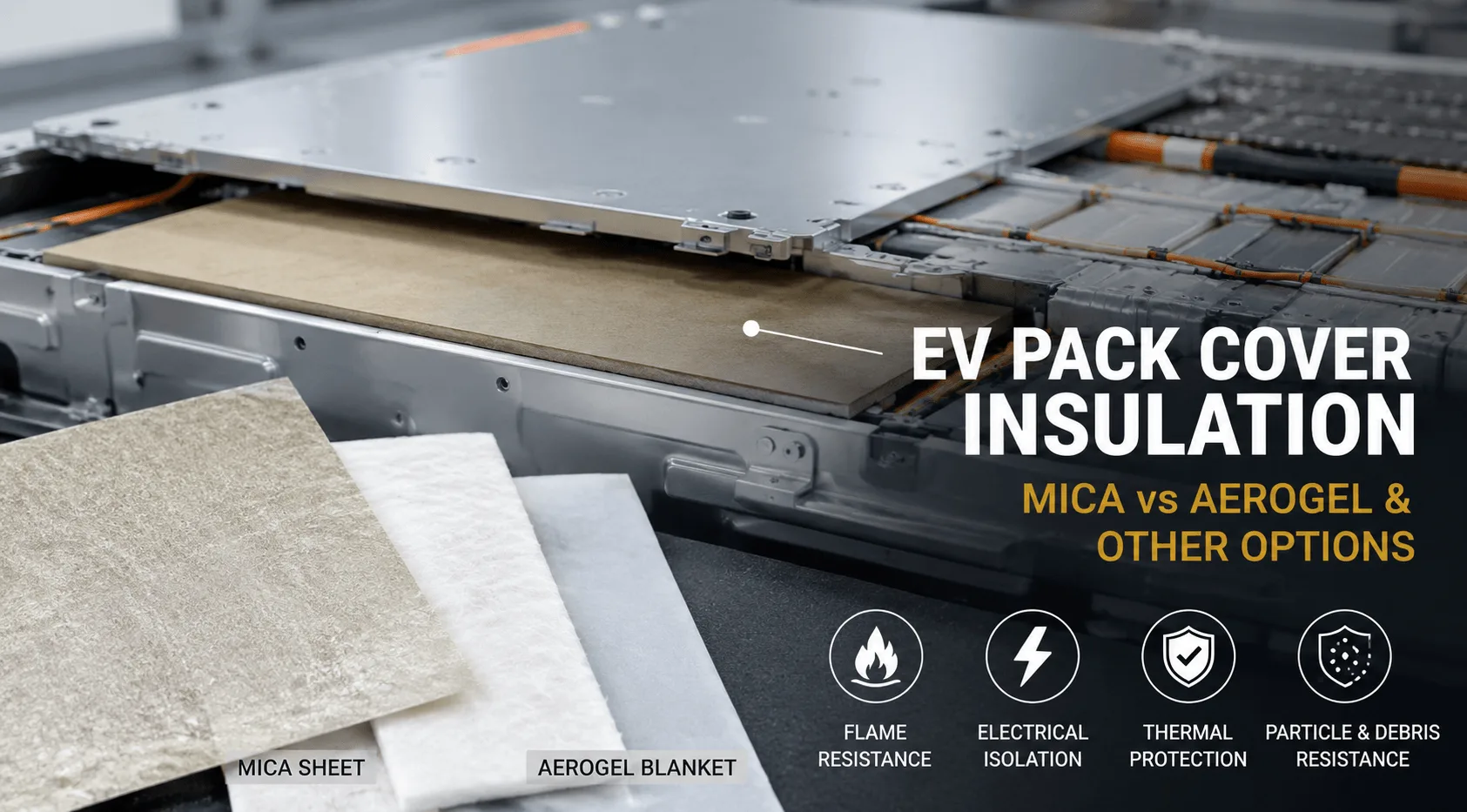
Which Insulation Material Is Best Under EV Pack Covers?
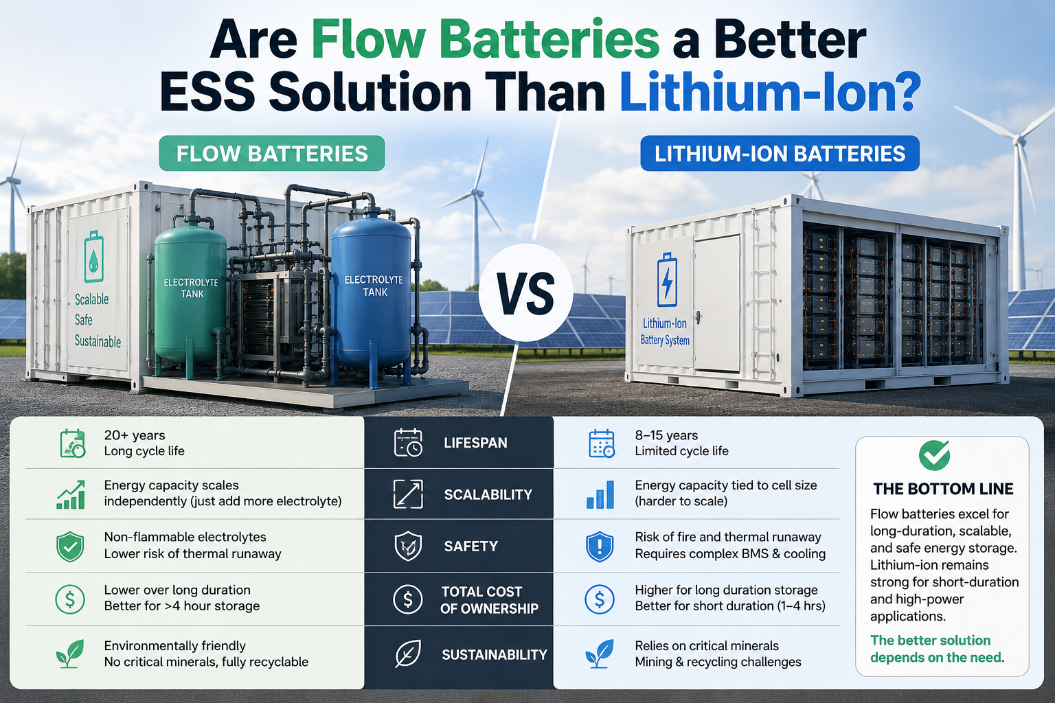
Are Flow Batteries a Better ESS Solution Than Lithium-Ion?

What Makes Flame Retardant Polycarbonate Ideal For Batteries?
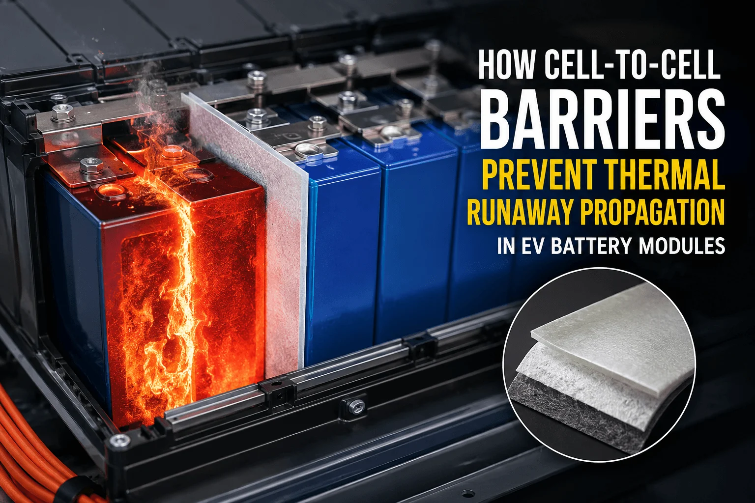
How Do Cell-to-Cell Barriers Prevent Thermal Runaway?
What is UL94 V0? Guide to Flame Retardant PC Film Testing
 betty wong