Where Is Aerogel Used Inside Modern EV Battery Packs?
Table of Contents
Open a modern EV battery pack and you may not see one obvious ‘aerogel layer‘. Instead, you will find thin barriers positioned exactly where heat, flame, or hot vent gas could reach the next cell or a critical structure. So where should aerogel actually go—and which apparently convenient locations can make normal cooling or emergency venting worse?
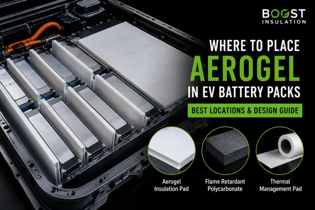
Aerogel is used inside modern EV battery packs at unwanted heat-transfer boundaries: between adjacent cells, between cell groups or modules, against end plates and sidewalls, under module or pack covers, and around—without blocking—designed vent paths. It may also form part of multi layer barriers protecting electrical and structural zones. The correct location is chosen by tracing conduction, radiation, flame, and hot-gas routes during a cell failure, while keeping aerogel out of the intended routine cooling path unless the complete design has been validated.
Engineering Takeaways
- Aerogel belongs across unwanted heat-transfer paths, not automatically between every cell or in the routine cooling interface.
- The most common locations are between cells, at module and structural boundaries, under covers, and beside controlled vent paths.
- Vent gas, metal bypass paths, compression, film, adhesive, and cutouts can matter as much as raw aerogel conductivity.
- The qualified component is the finished die-cut laminate in the real pack, followed by representative module and system testing.
The Placement Question Is Really a Heat-Path Question
The most useful way to decide where aerogel belongs is not to begin with a material catalog. Begin with a failure map. Identify the initiating cell, the surfaces that become hot first, the direction of the cell vent, the metallic structures that conduct heat, the neighboring cells that must remain below their failure threshold, and the enclosure surfaces that must be protected. Aerogel is then placed across the heat path that needs the greatest thermal resistance in the smallest available space.
This explains why two battery packs using the same chemistry can use aerogel in different positions. A prismatic module may place a pad across every broad cell face. A cylindrical design may use segmented interstitial barriers or group-level partitions. A pouch stack may use a thin compliant barrier that works with compression pads. A cell-to-pack architecture may use fewer individual pads but larger, continuous barriers around cell rows, structural beams, or cover interfaces.
The location must also be evaluated in the installed stack. Films, pressure-sensitive adhesive, edge seals, air gaps, compression, tabs, cutouts, and neighboring metal parts can create new thermal bridges or bypass routes. The finished die-cut laminate—not the raw aerogel core—is the component the battery system actually experiences.
Quick Location Map
The table below summarizes the most common locations, the function expected at each location, and the design mistake that should be avoided.
| Location | Primary Purpose | Common Format | Key Design Check | Main Risk |
| Between prismatic cells | Delay cell-to-cell transfer | Full-face die-cut pad | Compression and vent clearance | Edge bypass / thermal bridge |
| Pouch stack | Thermal barrier with pressure control | Reinforced or laminated sheet | Stack pressure and swelling | Local pressure concentration |
| Cylindrical rows | Interrupt row or group propagation | Strips, segments, partitions | Vent direction and cell retention | Volume loss / gas bypass |
| End plates / sidewalls | Isolate cells from structure | Aerogel + PC or mica | Fasteners and structural loads | Metal conduction path |
| Under covers / lids | Reduce upward heat and flame | Large sheet or hybrid shield | Pressure relief and erosion | Blocked gas flow |
| Vent channel walls | Protect adjacent cells and parts | Segmented, notched pieces | Open vent area and gas direction | Obstructed pressure relief |
| CTP / CTC boundaries | Protect cell rows and vehicle structure | Large continuous barrier | Support, flatness, assembly | Late architecture change |
1. Between Adjacent Prismatic Cells
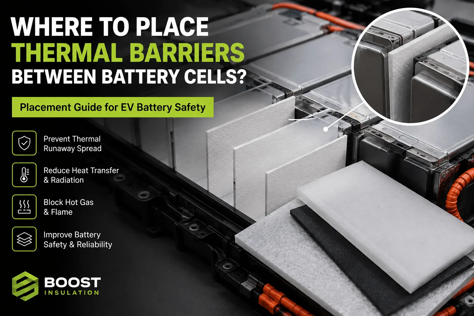
The broad face between large prismatic cells is one of the most common and technically direct locations for aerogel. A failing cell can heat the neighboring cell through face-to-face conduction, radiation, and hot gas moving around the top or side edges. A thin, full-face aerogel pad increases through-thickness thermal resistance while preserving pack energy density.
The pad is normally shaped to cover the active heat-transfer area while leaving controlled clearances for welds, terminals, sensors, vent features, frames, and assembly locators. Full geometric coverage does not mean the part should obstruct every opening. The designer must distinguish the surface that should be thermally isolated from the route that must remain open for pressure relief.
Installed compression is critical. Prismatic cells swell during cycling and the module may apply defined preload. Excessive compression can reduce the retained thickness of the aerogel composite and change its effective thermal resistance. Too little restraint can allow the part to move, wrinkle, or create inconsistent contact. The RFQ should therefore define nominal gap, minimum and maximum installed thickness, pressure range, cell swelling allowance, and end-of-life stack conditions.
Recent experimental work illustrates why location and thickness are evaluated together. In a 2025 study of large-format prismatic cells, aerogel barriers of 1, 2, 3, and 5 mm were placed between individual cells; even the 1 mm barrier substantially increased the propagation interval in that tested module. This is useful evidence that a thin inter-cell position can be effective, but it is not a universal thickness rule because cell energy, state of charge, gap geometry, trigger method, compression, cooling, and venting all change the result.
2. Between Pouch Cells or Pouch-Cell Groups
Pouch cells present a different mechanical problem. Their large flexible faces require controlled compression, and the barrier may need to accommodate dimensional change without creating local pressure peaks. Aerogel can be placed between individual pouches, between sub-stacks, or between a cell stack and a fire-resistant partition, depending on the pack architecture and validation target.
A bare brittle layer is rarely ideal for automated pouch assembly. Reinforced aerogel felt or a film-encapsulated laminate is easier to handle and less likely to shed dust. Silicone foam may be added as a separate compliance layer when the stack needs pressure distribution, vibration damping, or tolerance absorption. The two materials should not be treated as interchangeable: aerogel provides high thermal resistance, while silicone foam primarily controls mechanics and sealing.
The designer should also check whether the barrier changes stack stiffness or restricts the intended swelling path. A material that passes a bench thermal test can still cause problems if it concentrates load near pouch edges, interferes with cooling contact, or reduces the repeatability of module compression.
3. Around Cylindrical Cells and Cell Groups
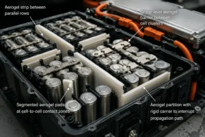
Cylindrical cells do not offer a simple flat interface, so aerogel placement is usually more architecture-specific. Options include narrow strips between rows, segmented pads at the closest cell-to-cell contact zones, molded or converted interstitial inserts, and group-level barriers that separate one cluster of cells from the next.
Attempting to wrap every cylinder with a thick insulating layer can consume volume, complicate cell retention, and interfere with normal heat rejection. In many designs, the better approach is to interrupt the most dangerous propagation route rather than surround every surface. This may mean a continuous barrier between parallel rows, a shield around a high-risk region, or a partition that combines aerogel with a rigid carrier.
Hot vent gas is especially important in cylindrical modules. Vents may direct jets toward the cell cap, busbar plane, or pack cover. A sidewall barrier that performs well against conduction may do little if hot particles travel over its top edge. The aerogel layout must therefore be coordinated with cell orientation, vent clearance, top-plate openings, gas channels, and pressure-relief strategy.
4. At Module End Plates and Sidewalls
Aerogel is often placed between the outermost cell and a metal end plate, side plate, cross member, or module wall. This location serves two purposes. First, it reduces heat transfer from the cell stack into a conductive structural member. Second, it can reduce the chance that the structure becomes a thermal bridge carrying energy around an otherwise effective inter-cell barrier.
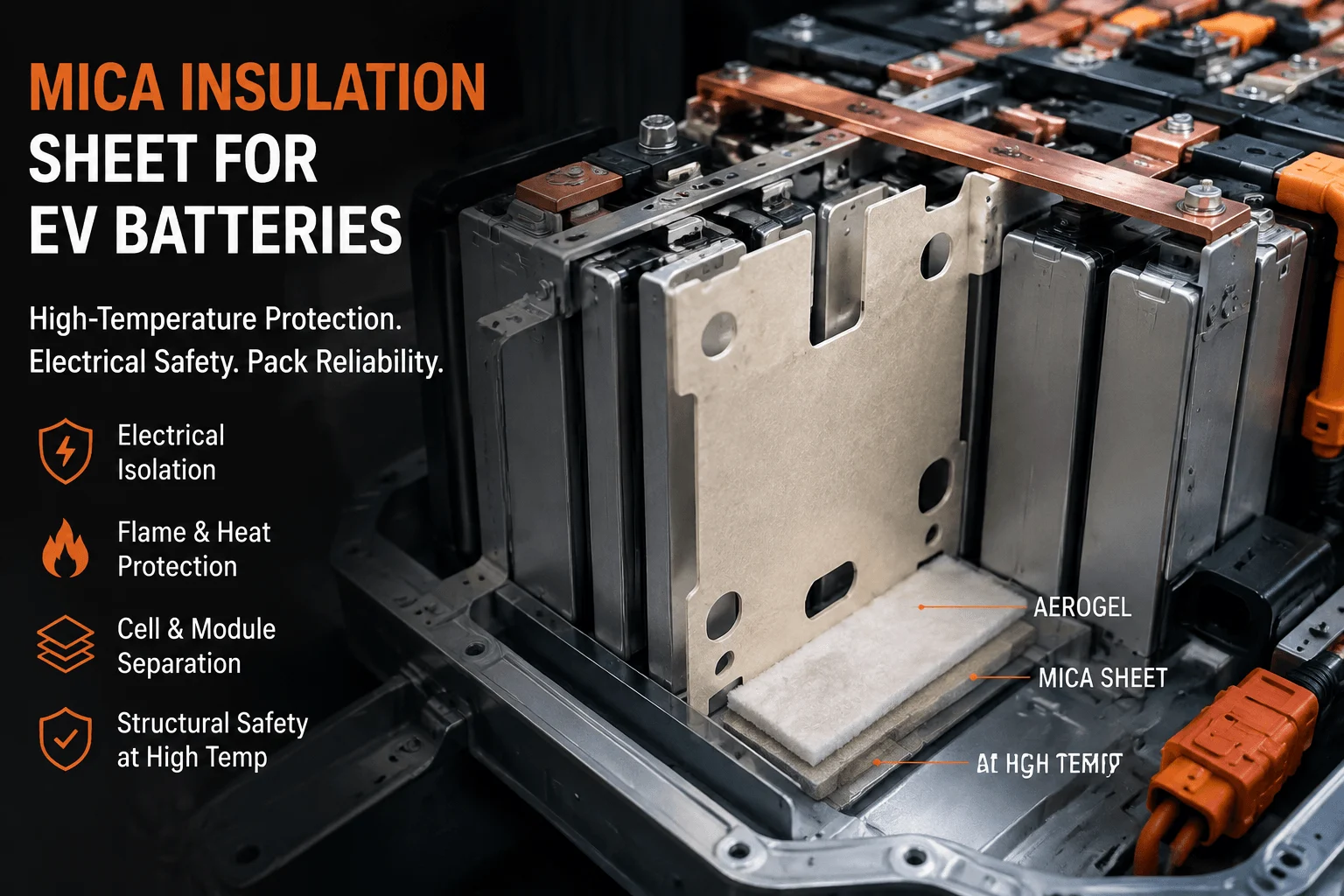
The challenge is that end plates are structural components. They carry preload, resist crash loads, and define module geometry. Aerogel alone is not normally the structural solution. A multilayer construction may use flame-retardant polycarbonate for rigidity and puncture resistance, aerogel for thermal resistance, and silicone foam for compliance or sealing. Mica may be added where sustained high-temperature shielding or arc resistance is needed.
Fasteners, tie rods, tabs, and metal frames must be treated as parallel conduction paths. A full-face aerogel pad can be bypassed by one uninsulated bolt or bracket. Thermal analysis and abuse testing should include these details rather than modeling the cell wall as an isolated flat surface.
5. Between Modules or Cell Groups
When a battery pack still uses discrete modules, aerogel can be placed in module-to-module partitions or at the boundary between cell groups. This creates a second level of protection: even if propagation occurs within one module, the pack designer may seek to prevent or delay transfer into the next module.
Group-level barriers are usually larger than individual cell pads and therefore introduce different manufacturing concerns. Flatness, dimensional stability, edge integrity, packaging, and installation support become more important. Large flexible parts may sag or fold during assembly. A rigid PC carrier, frame, locating holes, or temporary assembly liner can make the barrier easier to install without damaging the aerogel core.
A group partition should be continuous around the relevant heat path. Small gaps at cable passages, coolant connections, sensing harnesses, or structural beams may dominate the result. Cutouts should be minimized, located away from the hottest zones, or protected with overlapping secondary pieces when the electrical and service layout allows.
6. Under Module Covers and Pack Lids
Aerogel blankets or die-cut sheets can be installed above cells, below module covers, or beneath the main pack lid. The objective is not usually to isolate one neighboring cell; it is to reduce vertical heat flux, flame exposure, and hot-particle transfer toward the cover, passenger compartment, body structure, service components, or electronics.
This position is especially relevant when cell vents face upward. The barrier may be combined with mica, coated glass fabric, ceramic paper, or a metal shield. The correct stack depends on whether the primary threat is short-duration radiation, direct flame, high-velocity particles, prolonged hot gas, or electrical arcing. Aerogel provides low heat transfer, but a tougher facing layer may be needed to resist erosion or puncture.
The lid barrier must not block designed pressure relief. It may require channels, stand-offs, controlled clearances, or segmented pieces that guide gas toward vents. A continuous sheet placed without gas-flow analysis can increase local pressure or redirect hot gas toward a weaker region.
7. Around Vent Paths—But Never Across Them
A cell vent is a functional safety feature, not empty space available for insulation. Aerogel may be placed beside a vent path, behind a deflector, along the walls of a gas channel, or between the vent route and neighboring cells. It should not cover, seal, or narrow a pressure-relief opening unless the vent system was specifically designed and validated with that component.
This is one of the most common sources of false confidence. Engineers can create excellent face-to-face insulation while leaving a direct path for hot gas to travel around the barrier. The thermal event then bypasses the low-conductivity material entirely. A robust design treats venting as a three-dimensional flow problem involving gas temperature, velocity, particles, flame length, pressure, and the geometry of covers and channels.
Die-cut geometry matters here: Notches, slots, tabs, and asymmetric edges may be necessary to preserve vent clearance. These features should be identified on the drawing as safety-critical dimensions, not treated as cosmetic details.
8. Near Busbars, Terminals, and High-Voltage Zones
Aerogel can be part of a barrier that protects busbars, terminal regions, sensing components, or high-voltage structures from a nearby thermal event. However, the word part is important. Not every aerogel composite is qualified as a controlled electrical-insulation component, and its dielectric performance may change after adding film, adhesive, cut edges, contamination, humidity, or compression.
Where electrical isolation is a primary requirement, designers commonly add a defined dielectric layer such as flame-retardant polycarbonate, PET, polyimide, or mica. Aerogel then supplies the thermal resistance. The finished stack should be tested for dielectric strength, insulation resistance, creepage and clearance, puncture resistance, flame behavior, and aging in the actual thickness and configuration.
Busbar regions also contain metal paths that can conduct heat around the aerogel. Terminal bridges, welds, brackets, and sensing plates should be included in the heat-path review. Protecting the cell face while leaving a highly conductive busbar route untreated may move the propagation path rather than remove it.
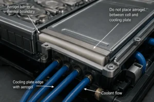
9. At Cooling-Plate Edges and Thermal Boundaries
Aerogel may be used near the edges of a cooling plate, between a hot cell region and a structural rail, or at a boundary where the designer wants to prevent lateral heat spreading. It should generally not be inserted between a cell and the cold plate when that interface is the intended path for normal heat removal.
This distinction separates thermal insulation from thermal management. Thermal interface pads, gels, and gap fillers conduct routine heat toward the coolant system. Aerogel resists heat crossing an unwanted boundary. If a designer places a low-conductivity layer in the normal cooling path, cell temperature and temperature non-uniformity may increase during driving or fast charging.
The relationship is not always simple. Research has shown that aerogel and liquid cooling can work synergistically in some tested module configurations, while other studies warn that a low-conductivity barrier can trap heat if the cooling and venting architecture is not coordinated. This is why the barrier location must be evaluated under both normal operation and abuse conditions.
10. In Cell-to-Pack and Cell-to-Chassis Structures
Modern cell-to-pack and cell-to-chassis designs remove or reduce traditional module hardware. This can improve energy density and reduce part count, but it also changes where passive thermal barriers can be supported, located, and replaced. Aerogel may be positioned between cell rows, along structural beams, above cell groups, around pack zones, or at the interface between the cell array and vehicle structure.
The industry insight is that aerogel placement is shifting from a simple component choice to an architecture decision. Fewer module walls mean fewer default separation planes. The thermal barrier may need to perform over a larger area and work directly with load-bearing structures, adhesives, cooling plates, and the pack cover. Manufacturing yield and installation repeatability become as important as raw thermal conductivity.
Larger integrated barriers also increase the cost of late design changes. Edge seals, cutouts, alignment features, carrier films, and packaging should be developed before the pack tooling and automated assembly sequence are frozen.
How PC Insulation, Silicone Foam, and Mica Work With Aerogel
Aerogel rarely performs every required function by itself. A high-value battery insulation system assigns each material a specific job. Aerogel resists heat transfer. Flame-retardant polycarbonate adds rigid electrical isolation, clean handling, dimensional stability, and puncture resistance. Silicone foam manages compression, vibration, sealing, and tolerance. Mica adds inorganic high-temperature and arc-resistant shielding.
A typical converted part might use an aerogel core encapsulated in PET or PI film, partial pressure-sensitive adhesive for assembly, a release liner with a pull tab, and a separate PC or mica carrier. Another design may place silicone foam adjacent to—not over the entire face of—the aerogel to maintain stack pressure while limiting the creation of a conductive bridge.
The stack should be simplified wherever possible. Every added layer can change thickness, stiffness, thermal resistance, flame performance, moisture behavior, die-cut quality, and cost. The best laminate is not the one with the most materials; it is the minimum construction that meets the system requirements with manufacturing margin.
| Material | Primary Function | Best Location | Why It Complements Aerogel | Qualification Focus |
| Aerogel | Thermal resistance | Cells, partitions, covers | Slows unwanted heat transfer | Installed thickness and abuse tests |
| FR Polycarbonate | Rigid dielectric support | End plates, frames, carriers | Adds puncture resistance and clean handling | UL rating, dielectric, temperature |
| Silicone Foam | Compliance and sealing | Gaps, pressure zones, edges | Controls tolerance, vibration, and preload | Compression set and aging |
| Mica | High-temperature shield | Lids, busbars, fire zones | Adds inorganic flame and arc resistance | Brittleness and conversion quality |
How to Choose the Correct Location
- Define the initiating event: Specify the cell, trigger method, state of charge, expected vent direction, hot-surface exposure, and the neighboring component that must be protected.
- Trace all heat-transfer paths: Include cell-face conduction, radiation, gas and flame flow, cooling plates, busbars, fasteners, frames, lids, and coolant connections.
- Protect the vulnerable receiver: The barrier should keep the adjacent cell, cover, electrical component, or structure below the relevant temperature, flame, or dielectric limit for the required time.
- Preserve intended functions: Do not compromise normal cooling, pressure relief, sensing, electrical clearances, cell swelling, service access, or crash structure.
- Validate the installed stack: Test the converted part at the real thickness, compression, aging state, adhesive coverage, edge condition, and assembly orientation.
- Confirm production repeatability: A location is only viable if the part can be cut, handled, aligned, inspected, packed, and installed consistently at volume.
Die-Cut Design and Manufacturing Considerations
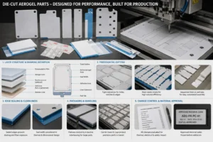
A battery aerogel part begins with geometry, but production success depends on the complete stack. The converter needs to understand which side faces the cell, whether the film seams may overlap, whether adhesive coverage is full or patterned, where the release liner must split, how operators or robots will grip the part, and which dimensions are safety-critical.
Edge control is important because exposed aerogel can shed dust or absorb handling damage. Encapsulation and sealed edges improve cleanliness, but the seal width consumes active area and can create a different thermal path. The drawing should distinguish total outline, active aerogel area, seal width, adhesive area, liner extension, and pull-tab dimensions.
Large parts require flatness and packaging controls. Small inter-cell pads require tight pitch, hole, and notch tolerances. Complex parts may benefit from kiss-cut delivery on a carrier liner, multi-cavity sheets, or sequential release liners that support automated assembly. The optimal format depends on annual volume, takt time, operator access, and traceability requirements.
Change control is essential. Substituting a film, adhesive, reinforcement, or aerogel core may affect thermal resistance, dielectric behavior, flammability, thickness, peel strength, and abuse-test performance. Approved material codes and alternates should be frozen before validation samples are built.
Validation: Location Must Be Proven at Three Levels
Level 1 — material screening. Confirm thermal conductivity across relevant temperatures, density, thickness tolerance, thermal stability, flame behavior where applicable, dielectric properties if claimed, compression response, moisture behavior, and mechanical handling characteristics.
Level 2 — converted-part qualification. Test the complete laminate for dimensions, flatness, seal integrity, peel strength, liner release, dust, puncture, dielectric strength, insulation resistance, aging, vibration, humidity, thermal cycling, and compression. UL 94 information can help screen polymeric films and carriers, but UL explicitly describes these as small-scale material tests; a V-0 or VTM-0 rating is not proof of pack-level thermal-runaway performance.
Level 3 — module and pack verification. Use representative cells, state of charge, compression, cooling, venting, structure, electrical connections, sensors, warning logic, and triggering methods. UN Regulation No. 100 Revision 3 includes system-level thermal-propagation and warning provisions, underscoring that the complete rechargeable energy storage system—not one material data sheet—is the compliance unit.
The test plan should measure more than whether the next cell enters thermal runaway. Record temperature rise, propagation interval, gas and flame path, cover exposure, electrical isolation, pressure, structural damage, and post-test integrity. The final design should include manufacturing and aging margins rather than relying on a single best-case test.
Validation hierarchy: material data screens the grade; converted-part testing qualifies the laminate; module and pack abuse testing proves the selected location in the full safety system.
Common Placement Mistakes
- Putting aerogel in the intended cooling path and increasing normal cell temperature.
- Covering or narrowing a designed cell vent or pressure-relief channel.
- Protecting the cell face but ignoring hot gas that travels around the top edge.
- Ignoring heat conducted through busbars, cooling plates, frames, bolts, or brackets.
- Using raw-core thermal conductivity to represent a compressed, laminated part.
- Assuming a polymer film’s UL 94 rating proves thermal-runaway protection.
- Adding full-area adhesive without checking thermal bridging or flame behavior.
- Selecting thickness without accounting for cell swelling and end-of-life compression.
- Freezing pack tooling before the barrier can be handled and installed reliably.
- Changing film, adhesive, or core grade after validation without re-qualification.
RFQ Checklist for Aerogel Placement Parts
- Cell format, chemistry, capacity, energy, state of charge, and module layout.
- 2D drawing plus a pack or module cross-section showing neighboring parts.
- Initiating-cell location, expected vent direction, and thermal-abuse target.
- Protected component and maximum allowable temperature or exposure time.
- Nominal gap, tolerance stack, installed pressure, and swelling allowance.
- Cooling-plate, busbar, fastener, frame, cover, and gas-channel locations.
- Required aerogel thickness, film, adhesive pattern, liner, tabs, and edge seal.
- Dielectric, flame, aging, cleanliness, dimensional, and traceability requirements.
- Prototype quantity, annual volume, packing format, validation date, and SOP target.
Frequently Asked Questions
Is aerogel always placed between every battery cell?
No. Full cell-to-cell coverage is common in prismatic and some pouch designs, but cylindrical and highly integrated packs may use row barriers, group partitions, cover barriers, or structural-zone protection instead.
Can aerogel be installed directly on a cell?
It can be, provided the film, adhesive, cleanliness, compression, electrical requirements, vent clearance, and cell-surface compatibility are validated. Direct contact is not automatically better than a controlled air gap or carrier-supported barrier.
Should aerogel go between the cell and cooling plate?
Usually not if that interface is the planned routine heat-removal path. Aerogel belongs across unwanted heat-transfer routes. Any exception requires thermal and abuse validation.
Can aerogel protect a pack lid?
Yes. Aerogel can reduce vertical heat flux under module or pack covers, often with mica, fabric, film, or metal facing. The stack must preserve pressure relief and resist gas, flame, and particle exposure.
Can aerogel protect busbars?
It can provide thermal resistance near busbars, but electrical insulation must be verified on the finished laminate. A defined PC, PET, PI, or mica dielectric layer may be required.
Does thicker aerogel always allow a smaller safety gap?
Not automatically. Thickness can improve thermal resistance, but it also affects compression, cooling, cell expansion, pack height, venting, cost, and manufacturing. System testing determines the usable trade-off.
Why use a film-encapsulated aerogel part?
Encapsulation can improve cleanliness, edge durability, handling, adhesive bonding, and automated assembly. It can also change thermal and flame performance, so the final construction must be tested.
What information should be sent for a fast quotation?
Send the cell and module layout, part drawing, available gap, compression range, vent location, material stack, performance targets, prototype quantity, annual demand, and required documents.
Place the Barrier Where the Failure Travels
Aerogel is used inside modern EV battery packs wherever an unwanted heat path must be slowed without consuming excessive space: between cells, between groups, against structural boundaries, beneath covers, and beside controlled vent routes. The strongest design does not simply add more aerogel. It places the correct finished laminate across the dominant propagation path while preserving cooling, venting, electrical isolation, compression and manufacturability.
For an actionable supplier review, share the cell format, pack section, vent direction, cooling layout, available gap, compression range, protected component, thermal target, dielectric requirements, layer preferences, prototype quantity, and annual volume. Boost Insulation can evaluate aerogel, flame-retardant polycarbonate, silicone foam, mica, films, adhesives, and die-cut delivery formats as one production-ready insulation system.
| Need a Placement Review for an Aerogel Barrier?
Send the cell format, pack section, vent direction, cooling layout, gap, compression range, protected component, thermal target, dielectric requirement, drawing, prototype quantity, and annual volume. Boost Insulation can review aerogel, PC, silicone foam, mica, films, adhesives, and die-cut delivery as one manufacturable stack. |
Technical Sources
- Boost Insulation: EV battery insulation, aerogel conversion, precision die-cutting, and quality-system information. Source
- Boost Insulation: Aerogel insulation product and custom conversion information. Source
- Boost Insulation: EV battery module insulation and cell-to-cell protection solutions. Source
- United Nations Economic Commission for Europe: UN Regulation No. 100, Revision 3: rechargeable energy storage system and thermal-propagation provisions. Source
- Mao T. et al: Effects and mechanisms of thickness-tunable aerogel thermal barriers on suppression of thermal runaway propagation in large-format prismatic lithium-ion batteries. Materials Today Energy 2025; 101996. DOI: 10.1016/j.mtener.2025.101996. Source
- Wong S.K. et al: Mitigating thermal runaway propagation in high specific energy lithium-ion battery modules using nanofiber aerogel. Energy 2024. DOI: 10.1016/j.energy.2024.132353. Source
- Yang X. et al: An Experimental Study on Preventing Thermal Runaway Propagation in Lithium-Ion Battery Module Using Aerogel and Liquid Cooling Plate Together. Fire Technology 56 (2020), 2579-2602. DOI: 10.1007/s10694-020-00995-x. Source
- UL Solutions: Combustion tests for plastics: UL 94 V, VTM, 5V, and related small-scale test criteria. Source
- Zhou Z. et al: Experimentally exploring prevention of thermal runaway propagation of a large-format prismatic lithium-ion battery module. Applied Energy 327 (2022), 120119. DOI: 10.1016/j.apenergy.2022.120119. Source
- Hou X. et al: Thermal Insulation and Fireproof Aerogel Composites for Battery Safety: A Review. Gels 2025, 11, 791. Source
Related Posts:
How Does Cell-to-Cell Thermal Barrier Improve ESS Safety?
How Does Flame Retardant Polycarbonate Compare to FR ABS Plastic?
Where Should Thermal Barriers Be Placed Between Cells?

What Is ESS Energy Storage Solution & How It Works?
Why EV Battery Modules Need Specialized Insulation?
How Does a Mica Insulation Sheet Protect EV Batteries?
 betty wong