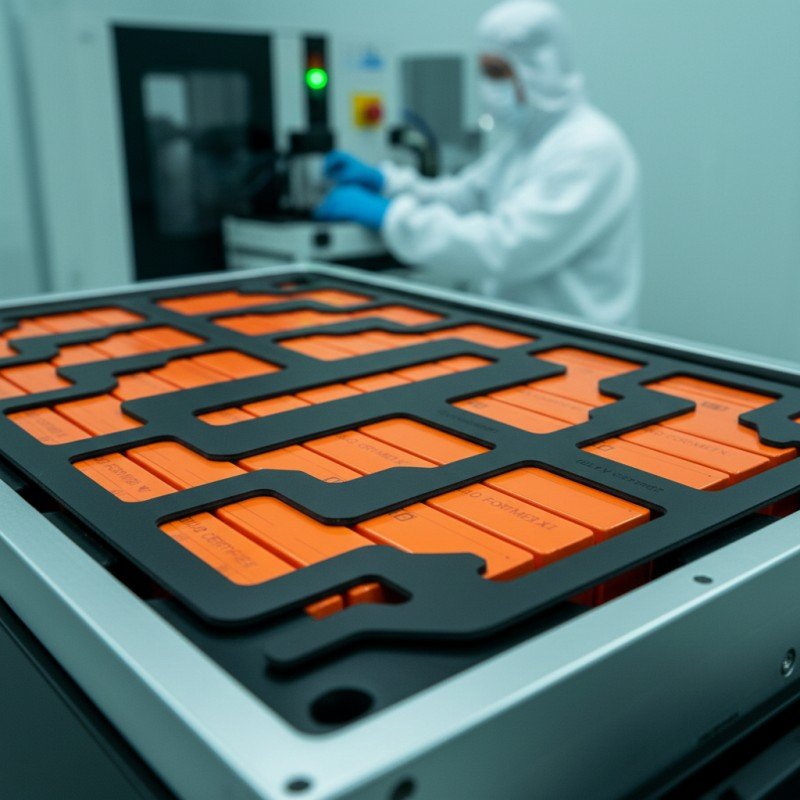
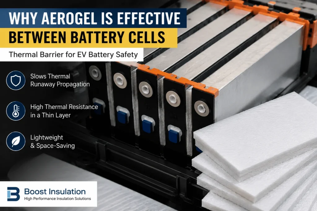
What Makes Aerogel Effective Between Battery Cells?
Table of Contents
Two high-energy battery cells can be separated by only a few millimeters, yet one failing cell may expose the next cell to intense surface heat, radiation, hot gas, and ejected particles. How can a thin barrier inside that restricted gap slow the event without disrupting cooling, compression, venting, or automated assembly? That is the engineering reason aerogel has become a serious cell-to-cell insulation option.
Aerogel is effective between battery cells because its nanometer-scale porous network restricts solid and gas-phase heat transfer, creating high thermal resistance in a thin, lightweight layer. When the aerogel is reinforced, correctly compressed, protected by suitable films, and positioned across the real heat path, it can slow temperature rise in adjacent cells and delay thermal runaway propagation.
Engineering Takeaways
- Aerogel is effective because it delivers substantial through-thickness thermal resistance within the narrow spacing available between cells.
- The finished cell barrier is not just aerogel: reinforcement, film, adhesive, edge seal, compression, and cut geometry can improve or weaken performance.
- Thickness generally increases propagation delay, but test results cannot be transferred directly between different cell chemistries, states of charge, trigger methods, and module structures.
- Aerogel slows unwanted heat transfer; it should not replace the normal thermal interface that conducts routine cell heat toward the cooling system.
- Material data is only the first screening level. The converted part and the representative module or pack must be validated under installed conditions.
Why the Space Between Cells Is So Difficult to Protect
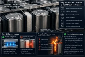
The cell-to-cell gap is one of the most demanding locations in an EV battery pack. It must often perform several functions at once: maintain electrical separation, tolerate cell swelling, preserve stack preload, resist vibration, remain dimensionally stable, fit around tabs or vents, and occupy very little volume. During normal operation, the same region may need to support controlled heat flow toward a cooling plate. During an abuse event, however, the designer wants to resist lateral heat transfer from the initiating cell to its neighbor.
This creates a design conflict. A highly conductive interface is useful when the objective is to remove everyday operating heat. A highly resistive barrier is useful when the objective is to protect an adjacent cell from a localized thermal event. The correct battery architecture therefore separates these functions. Thermal interface pads, gels, and gap fillers connect intended heat paths to the cooling system; aerogel is placed across unintended propagation paths between cells, groups, or structures.
The problem is also transient rather than steady-state. A neighboring cell is not simply exposed to a warm surface. It may experience rapid heating, intense radiation, hot vent gas, flame, conductive metal paths, and mechanical movement. Aerogel is valuable because it addresses a major part of this transient heat load in a compact layer, but the complete barrier must also manage the paths that can travel around or through the aerogel.
1. A Nonporous Structure Restricts Heat Conduction
The defining feature of silica aerogel is its highly porous solid network. Much of the material volume is occupied by very small pores rather than continuous solid matter. This limits the cross-sectional area available for heat to move through the solid skeleton. The tortuous path through the reinforcing network also makes direct conduction less efficient than it would be through a dense polymer, ceramic sheet, or metal spacer.
At the cell interface, this low through-thickness conduction is the first reason aerogel works. Heat arriving from the hot cell face encounters a material that does not readily pass energy to the protected cell face. The result is a slower temperature increase on the cold side and a longer interval before the neighboring cell reaches a critical condition. The useful metric is not simply the lowest catalog thermal conductivity; it is the thermal resistance of the complete installed barrier at the required thickness and temperature.
One peer-reviewed study of glass-fiber-supported aerogel felt reported thermal conductivity around 0.017 to 0.023 W/m•K for the tested material and found that thicker barriers delayed thermal runaway propagation in an 18650-cell array. These values illustrate why aerogel is attractive, but they should not be copied into a new design specification without confirming the actual grade, reinforcement, temperature range, compression, and test method.
2. Nanometer-Scale Pores Limit Gas-Phase Heat Transfer
A conventional open air gap can reduce direct solid contact, but gas inside the gap can still transfer heat. Larger gaps may also support natural convection, and a venting cell can replace the relatively calm air with hot moving gas. Aerogel divides the gas phase into extremely small pores, limiting molecular transport and suppressing bulk convection within the material.
This matters because a cell-to-cell barrier must remain effective in a very small package. A thin aerogel composite can provide more resistance than the same thickness of many conventional foams or films. The material is therefore useful when pack designers are unwilling to sacrifice significant energy density for a large passive air space. The benefit is especially relevant in tightly packed prismatic and pouch-cell modules where broad faces sit close together.
The pore network does not mean that hot vent gas can be ignored. Gas can travel around an undersized pad, through a notch, along an unsealed edge, or above the cells. Aerogel is effective inside its covered area; the pack geometry must prevent high-energy gas and flame from bypassing that area.
3. High Thermal Resistance Is Available in a Thin Layer
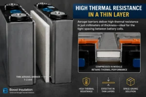
Battery engineering is governed by thickness budgets. A barrier that performs well at 10 or 20 mm may be impractical between production cells. Aerogel offers an unusually favorable relationship between thermal resistance and thickness, which is why it appears in millimeter-scale cell-to-cell pads and laminated barriers.
Thickness still matters. In general, a thicker layer provides a longer heat path and higher thermal resistance. Both the 2022 aerogel-felt study and a 2024 experimental study of nanofiber aerogel in high-specific-energy battery modules reported longer propagation intervals as barrier thickness increased. A 2025 investigation of thickness-tunable aerogel barriers in large-format prismatic cells likewise treated thickness as a central design variable. The engineering conclusion is not that one universal thickness exists; it is that thickness must be selected against a defined thermal target and installed gap.
The apparent thickness on a material data sheet may not equal the retained thickness in the module. Compression from end plates, cell swelling, tolerance stack-up, adhesive coverage, and local ribs can reduce the effective thickness. Qualification should therefore use installed thickness under realistic pressure, not only the free-state thickness measured on a loose sheet.
4. Reinforced Aerogel Can Survive Conversion and Assembly
Pure monolithic silica aerogel is too fragile for most high-volume cell assembly. Battery-grade products are commonly reinforced with glass fiber, ceramic fiber, polymer fiber, or other carriers to create a felt, blanket, mat, or composite sheet. This reinforcement provides enough integrity for slitting, laminating, die cutting, handling, placement, and compression.
Mechanical integrity is part of thermal performance. A cracked, folded, contaminated, or locally crushed barrier may leave a direct thermal bridge. Conversely, a reinforced pad that remains flat and continuous can preserve coverage across the cell face. The reinforcement also influences density, compressibility, dust generation, puncture behavior, and high-temperature response, so two products labeled “aerogel” may behave differently in the same module.
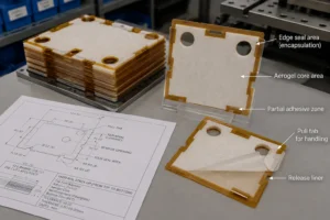
For automation, the barrier may be encapsulated in PET, polyimide, or another film. Encapsulation can improve cleanliness, tear resistance, placement accuracy, and operator handling. It may also allow partial pressure-sensitive adhesive, release liners, pull tabs, and carrier formats. However, the added films and adhesives become part of the thermal and flammability system; they must be selected and validated rather than treated as invisible processing aids.
5. Aerogel Can Be Engineered for Cell Swelling and Stack Pressure
Prismatic and pouch cells change dimensions during formation, cycling, aging, and thermal events. The inter-cell material must fit within the module pressure strategy. Some aerogel composites offer controlled compressibility and can accommodate small variations without eliminating the thermal barrier. Other grades are stiffer and are better suited to stable gaps or hybrid constructions.
The key is not maximum softness. If the barrier is too compliant, it may over-compress, lose retained thickness, or allow the cells to move. If it is too stiff, it may concentrate pressure, interfere with swelling accommodation, or create local stress. Engineers should request compression-deflection data, retained thickness, recovery, and cycling behavior over the expected temperature and pressure range.
Silicone foam is often used beside or around aerogel when the design needs more compliance, sealing, vibration damping, or tolerance absorption. Aerogel supplies thermal resistance; the foam manages controlled compression and gaps. A rigid flame-retardant polycarbonate carrier can add puncture resistance, accurate geometry, and dielectric support. This division of functions is usually more reliable than forcing one material to perform every task.
6. The Barrier Can Also Support Electrical Separation
Silica-based aerogel is generally electrically nonconductive, which can support isolation between cell cans, cases, or structural components. However, electrical insulation must be specified for the finished construction. Reinforcement fibers, conductive contamination, surface moisture, metal particles, adhesive chemistry, film defects, cut edges, and compression can change the measured result.
For a high-voltage EV pack, designers should define dielectric strength, insulation resistance, creepage and clearance, puncture resistance, and the required test method. If electrical isolation is a primary safety function, aerogel may be combined with a dedicated dielectric layer such as flame-retardant polycarbonate, PET, polyimide, or mica. The aerogel then handles heat transfer while the dielectric layer provides a more controlled electrical barrier.
This distinction improves procurement accuracy. Asking only for “insulating aerogel” is not enough. The RFQ should identify whether the part is a thermal-only spacer, a thermal-and-electrical laminate, or a multifunctional compression pad. Each category requires different tests and manufacturing controls.
7. Aerogel Covers the Broad Cell Face Where Heat Transfer Is Strongest
Aerogel is especially effective between large prismatic or pouch cells because the broad opposing faces create a direct heat-transfer route. A full-face or near-full-face pad can interrupt conduction and reduce radiative coupling across the largest shared area. This is more efficient than placing a small patch far from the primary heat path.
Coverage must still preserve functional features. The pad may need clearances for cell vents, terminals, welds, sensors, locating pins, frames, cooling features, and adhesive-free zones. Each cutout reduces active barrier area and may create an edge path. The design objective is not maximum geometric coverage at any cost; it is continuous coverage across the heat-transfer area while keeping vents, electrical connections, and pressure-relief paths functional.
Cylindrical-cell modules require a different approach because curved cells do not create one broad flat interface. Aerogel may be used as strips between rows, segmented barriers between cell groups, molded or flexible partitions, or barriers under busbar and cover regions. The correct location depends on vent direction, holder geometry, cell spacing, coolant layout, and the intended propagation boundary.
Why Aerogel Works—and What Can Defeat It
| Performance Mechanism | Engineering Benefit | Critical Design Variable | Common Failure Mode |
| Low solid conduction | Slower heat flow through the cell face | Core composition and density | Dense reinforcement or compression bridge |
| Restricted gas conduction | High resistance in a thin gap | Pore structure and temperature | Hot gas bypasses pad edges |
| Added thickness | Longer propagation interval | Installed compressed thickness | Nominal thickness not retained |
| High-temperature stability | Barrier remains longer during abuse | Complete laminate construction | Film or adhesive fails first |
| Broad-face coverage | Interrupts the dominant cell-to-cell path | Pad dimensions and cutouts | Gaps, tabs, or metal bridges |
| Reinforced handling | Supports die cutting and automation | Carrier, encapsulation, edge seal | Dust, cracking, delamination |
How Aerogel Responds to the Main Thermal Runaway Paths
Direct Contact and Cell-Face Conduction
When neighboring cells are tightly compressed, the broad faces can transmit energy rapidly through any solid material between them. Aerogel reduces this path by providing low through-thickness conductivity. The effect is strongest when the pad remains continuous and retains its designed thickness.
Thermal Radiation
A hot cell surface and flame can radiate energy toward nearby cells. The aerogel matrix and reinforcing structure reduce direct line-of-sight exposure across the covered face. Surface films, coatings, or reflective layers may change radiative behavior and should be included in heat-exposure testing.
Hot Gas, Flame, and Ejected Particles
Aerogel can resist heat through the pad, but a vent jet can move around it. Vent direction is therefore a first-order input. Pads must not obstruct designed cell vents. Instead, the architecture may combine cell-face aerogel with mica or metal deflectors, insulated channel walls, pack-lid barriers, and controlled exhaust routes. Edge seals should resist handling without creating a closed pressure pocket.
Metal Thermal Bridges
Busbars, cell holders, compression plates, fasteners, cooling plates, and structural rails can carry heat around the inter-cell pad. A successful barrier design maps these parallel paths. A full-face aerogel pad can appear excellent in a coupon test while the real module transfers heat through a bolt, bracket, or continuous aluminum member.
Mechanical Movement
Thermal runaway can cause swelling, venting forces, deformation, and loss of preload. The barrier should not shift, fold, or tear under these conditions. Geometry, locating features, adhesive pattern, carrier film, and surrounding foam can be as important as the thermal conductivity of the core.
The Seven Variables That Decide Real Cell-to-Cell Performance
- Cell chemistry and state of charge: High-energy chemistries and high SOC can produce more severe thermal events. Barrier results from one chemistry or SOC are not automatically transferable.
- Trigger method: Heating, overcharge, nail penetration, internal short simulation, or other triggers create different heat release, venting, and timing.
- Cell format and orientation: Prismatic, pouch, and cylindrical cells expose different surfaces and vent directions, changing where aerogel is most effective.
- Installed thickness and pressure: Free-state thickness is not enough; compression and swelling determine the actual thermal resistance in the module.
- Coverage and bypass paths: Cutouts, edge gaps, frames, busbars, fasteners, and cooling structures can route heat around the barrier.
- Complete laminate construction: Films, adhesives, release liners, reinforcements, and edge seals alter thermal, mechanical, dielectric, and flame behavior.
- Cooling and venting architecture: Aerogel must work with the cooling plate and pressure-relief strategy, not block them.
How Aerogel Compares With Other Inter-Cell Materials
| Material | Primary Job | Strength Between Cells | Main Limitation | Best Use With Aerogel |
| Aerogel composite | Thermal resistance | High resistance at low thickness | Needs protection and system validation | Core thermal barrier |
| FR polycarbonate | Rigid dielectric isolation | Puncture resistance and geometry | Not a high-performance thermal barrier | Carrier, end plate, electrical layer |
| Silicone foam | Compression and sealing | Tolerance control and vibration damping | Usually higher heat transfer than aerogel | Perimeter seal or pressure layer |
| Mica sheet | High-temperature fire/electrical shield | Inorganic heat and arc resistance | Brittle; limited compliance | Lid, vent, busbar, hybrid shield |
| Thermal interface pad | Conduct heat to coolant | Improves routine cooling | Opposite function to an inter-cell barrier | Cooling interface, not propagation barrier |
Industry Insight: The Market Is Moving From “Material Rating” to “Propagation Time”
Battery programs increasingly judge a thermal barrier by what it does in the assembled system rather than by a single material property. UNECE Regulation No. 100 Revision 3 introduced requirements related to thermal propagation, warning, and occupant egress for rechargeable electrical energy storage systems. OEM and Tier 1 validation plans therefore focus on the time between initiation and hazardous conditions, the temperature of neighboring cells, gas and flame behavior, and the integrity of pack structures.
This shift explains why a low conductivity value is necessary but insufficient. Two aerogel pads with similar room-temperature conductivity may behave differently after compression, at elevated temperature, under flame erosion, or after their films and adhesives age. The market is also moving toward cell-to-pack and cell-to-chassis architectures, which remove some traditional module walls. In these designs, cell-to-cell barriers become part of the pack architecture rather than a late-added accessory.
Fast charging and higher energy density also increase the value of precise passive protection. Aerogel does not prevent the initiating defect, and it does not replace sensors, battery management logic, cooling, venting, or structural fire shields. Its role is to reduce the rate at which a local failure recruits neighboring cells. Even a delay can be valuable when it supports detection, warning, isolation, emergency response, or controlled venting.
Why UL 94 V-0 Is Not the Same as Thermal Runaway Protection
Some inter-cell barriers include polymer films, pressure-sensitive adhesives, polycarbonate carriers, or silicone foams with UL 94 classifications. UL Solutions explains that UL 94 ratings are based on small-scale specimens exposed to defined flames under controlled laboratory conditions. V-0, V-1, V-2, VTM, and foam classifications use different specimen configurations and methods.[5] A VTM-0 thin-film rating is not equivalent to V-0, and neither rating proves that a battery module will stop thermal propagation.
Flame ratings remain useful for material selection and OEM requirements, but they must be verified at the correct thickness, color, formulation, and construction. The finished laminate may contain layers with different ratings. Qualification should therefore document the raw material evidence and separately validate the converted cell barrier and the representative battery assembly.
Die-Cut Design: How to Preserve Aerogel Performance in Production
A cell barrier that performs in a laboratory coupon can fail commercially if it cannot be converted and installed consistently. The die-cut supplier should review the complete drawing and stack-up before tooling. Key inputs include cell face dimensions, gap, compression range, vent location, terminal clearances, sensor features, adhesive zones, edge-seal width, liner design, assembly direction, cleanliness limit, and packaging method.
Cut quality matters because exposed or damaged edges can shed dust, lose reinforcement, or create local thin areas. Encapsulation may require a controlled perimeter seal around the aerogel core. That seal consumes width, so the drawing must distinguish the core coverage area from the outer film dimensions. Very narrow webs, sharp internal corners, closely spaced holes, and partial cuts can reduce yield or damage the laminate.
Adhesive should normally be applied only where needed for placement. Full-surface adhesive may increase stiffness, change thermal resistance, trap gas, or complicate removal. Partial adhesive zones, carrier liners, and pull tabs can improve assembly. The peel force should be high enough to retain the part during handling but not so high that the operator stretches or delaminates the barrier.
Production controls should cover thickness, dimensions, flatness, seal integrity, dust, surface contamination, peel strength, liner release, visual defects, lot traceability, and packaging pressure. Changes to the aerogel core, film, adhesive, reinforcement, or supplier should trigger engineering review because each component can alter the qualified result.
A Three-Level Validation Plan
Level 1: Material Screening
Screen thermal conductivity across the relevant temperature range, density, thickness tolerance, high-temperature stability, shrinkage, compression-deflection behavior, and flame response where required. Electrical testing may include dielectric strength, insulation resistance, puncture, and moisture conditioning. Material screening is used to narrow options; it is not the final safety claim.
Level 2: Converted-Part Qualification
Test the exact die-cut laminate, including reinforcement, films, adhesive pattern, edge seal, and manufacturing tolerances. Measure installed thickness under load, dimensions, flatness, dust, seal strength, peel and release force, aging, thermal cycling, vibration, and dielectric properties. Heat-exposure tests should evaluate the cold-side temperature and physical integrity of the complete part.
Level 3: Module and Pack Verification
Use representative cells, SOC, compression, cooling, electrical connections, venting, enclosure, sensors, and trigger method. Measure propagation interval, neighboring-cell temperatures, gas and flame path, pressure effects, cover exposure, electrical isolation, and post-test structure. This level determines whether aerogel between battery cells is effective in the actual product architecture.
Common Selection Mistakes
- Selecting a pad only by the lowest room-temperature thermal conductivity.
- Using free-state thickness while ignoring installed compression and swelling.
- Assuming that covering the cell face also controls vent gas and flame.
- Treating aerogel as a thermal interface pad for routine cooling.
- Ignoring busbars, fasteners, cooling plates, and frames that bypass the barrier.
- Qualifying the aerogel core but not the film, adhesive, edge seal, or die-cut part.
- Applying a material-level UL 94 rating as if it were a pack-level thermal propagation certification.
- Choosing a geometry that cannot be cut, handled, aligned, inspected, or installed repeatedly at production volume.
What to Include in an RFQ for Aerogel Cell Barriers
A high-quality RFQ lets the converter recommend a realistic construction rather than merely quote a material name. Include the following information:
- Cell chemistry, format, capacity, state-of-charge condition, and module arrangement.
- The protected cell or component, anticipated heat path, vent direction, and thermal performance target.
- Available free gap, installed compression range, cell swelling allowance, and required final thickness.
- Part drawing with dimensions, tolerances, cutouts, vent clearances, adhesive zones, pull tabs, and datum features.
- Electrical requirements such as dielectric strength, insulation resistance, creepage, clearance, and puncture resistance.
- Flammability, high-temperature, aging, chemical, vibration, cleanliness, and documentation requirements.
- Prototype quantity, annual volume, delivery format, packaging, traceability, PPAP/APQP, and change-control expectations.
Why a Precision Converter Matters
The aerogel manufacturer controls the core material, but the converter determines whether that material becomes a repeatable battery component. Precision die cutting, film lamination, partial adhesive application, edge sealing, liner design, cleanliness control, inspection, and packaging are all part of the finished barrier performance.
Boost Insulation positions its manufacturing around custom EV battery insulation and thermal management, including aerogel, mica, flame-retardant polycarbonate, silicone foam, films, adhesives, and precision die-cut parts. This multi-material capability is useful when an inter-cell solution needs a hybrid stack rather than a single sheet. The practical starting point is a module drawing and a clear description of the thermal, electrical, mechanical, and assembly targets.
| Need a Cell-to-Cell Aerogel Barrier Review? Send the cell format, gap, compression range, vent direction, drawing, thermal target, dielectric requirement, and prototype quantity. Boost Insulation can review material options, laminate structure, die-cut feasibility, and sampling requirements for your EV or BESS battery program.https://boostinsulation.com/ |
Frequently Asked Questions
Does aerogel completely prevent thermal runaway between cells?
Not automatically. Aerogel can slow heat transfer and may prevent propagation in a specific tested architecture, but the result depends on cell severity, SOC, thickness, coverage, compression, venting, cooling, structural paths, and the complete pack design.
What thickness of aerogel is best between battery cells?
There is no universal thickness. The correct value is the minimum installed thickness that meets the required cold-side temperature or propagation-delay target while fitting the gap and pressure strategy. Screening should compare several thicknesses in representative tests.
Is higher aerogel density always better?
No. Density affects solid conduction, mechanical strength, compression, handling, and mass. A denser material may be stronger but can conduct more heat. Select the full performance balance, not one property.
Can aerogel be placed directly against a cell?
Often yes, if the grade, surface film, cleanliness, compression, electrical requirements, and cell manufacturer guidance support direct contact. Some designs use an additional film, PC sheet, foam, or frame.
Does aerogel replace silicone foam between cells?
Usually not. Aerogel primarily resists heat transfer. Silicone foam primarily manages compression, gaps, sealing, and vibration. They can be used together when the module needs both functions.
Does aerogel replace a cooling plate or thermal pad?
No. Cooling plates and thermal interface materials remove normal operating heat. Aerogel resists unwanted heat transfer during a localized event. Their locations and functions should be separated.
Can aerogel cell barriers be die-cut with adhesive?
Yes. Reinforced and encapsulated aerogel can be precision die-cut and supplied with partial adhesive, liners, pull tabs, or carrier formats. The adhesive pattern and film stack must be qualified as part of the finished component.
What is the most important test for an aerogel barrier?
The most decision-relevant test is a representative module or pack thermal propagation test using the actual installed construction. Material and converted-part tests are necessary steps before that system-level verification.
Conclusion
Aerogel is effective between battery cells because it combines a nano porous low-conduction structure, strong thickness efficiency, high-temperature capability, and adaptable composite construction. Those properties can slow the rise of a neighboring cell temperature and increase the interval before propagation. The value is greatest across broad cell-face heat paths where a thin barrier is required.
The decisive word, however, is installed. The aerogel core, reinforcement, film, adhesive, edge seal, compression, coverage, vent path, cooling system, and surrounding metal all determine the result. A technically credible program selects the material against a defined thermal target, converts it into a controlled part, and validates the complete battery assembly.
For sourcing teams, the best inquiry is not “What is your lowest-conductivity aerogel?” It is “Can you build and document this cell-to-cell barrier for our actual gap, pressure, venting, dielectric, thermal, and production requirements?” That question leads to a component that can be engineered, tested, and manufactured—not just a promising material sample.
Technical References
- Liu, Q.; Zhu, Q.; Zhu, W.; Yi, X. “Influence of Aerogel Felt with Different Thickness on Thermal Runaway Propagation of 18650 Lithium-ion Battery.” Electrochemistry, 90 (2022), 087003. DOI: 10.5796/electrochemistry.22-00048.
- Wong, S. K.; Li, K.; Rui, X.; Fan, L.; Ouyang, M.; Feng, X. “Mitigating thermal runaway propagation in high specific energy lithium-ion battery modules through nanofiber aerogel composite material.” Energy, 307 (2024), 132353. DOI: 10.1016/j.energy.2024.132353.
- Mao, T. et al. “Effects and mechanisms of thickness-tunable aerogel thermal barriers on suppression of thermal runaway propagation in large-format prismatic lithium-ion batteries.” Materials Today Energy, 53 (2025), 101996. DOI: 10.1016/j.mtener.2025.101996.
- United Nations Economic Commission for Europe. UN Regulation No. 100, Revision 3: Uniform provisions concerning the approval of vehicles with regard to electric power train requirements.
- UL Solutions. “Combustion (Fire) Tests for Plastics” and UL 94 flammability classification guidance.
- Boost Insulation. EV battery insulation, aerogel insulation flame-retardant polycarbonate, silicone foam, thermal management, and precision die-cutting pages. https://boostinsulation.com/
Recommended On-Page SEO Checklist
- Use the exact primary keyword in the title, meta description, introduction, one H2, image ALT text, and a natural internal-link anchor.
- Add a diagram showing a hot initiating cell, an aerogel barrier, and the protected neighboring cell; label heat, vent-gas, and metal-bypass paths.
- Link to the Aerogel Insulation, EV Battery Module Insulation, Flame-Retardant Polycarbonate, Silicone Foam, and RFQ pages.
- Implement FAQPage schema only when the visible FAQ content is published on the page.
- Place an upload-drawing CTA after the DFM section and a sample/RFQ CTA after the conclusion.
- Review the article annually as battery safety standards, validation methods, and material constructions evolve.
Related Posts:
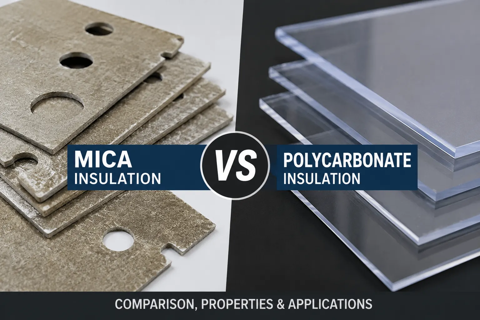
How Does Mica Insulation Compare With Polycarbonate?
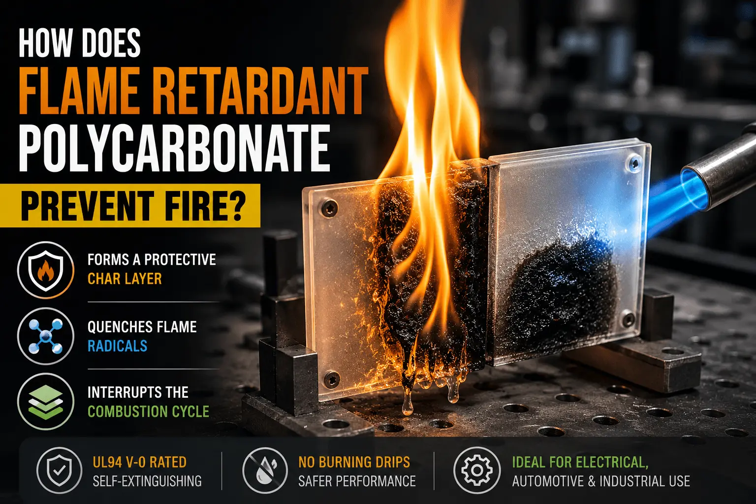
How Does Flame Retardant Polycarbonate Prevent Fire?
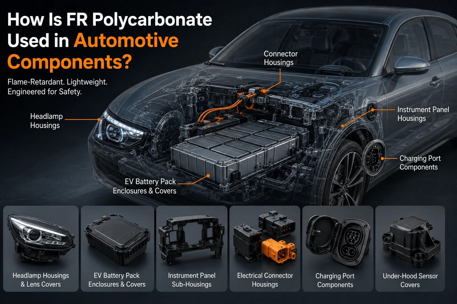
How Is FR Polycarbonate Used in Automotive Components?
What Insulation Does an Energy Storage System Need?
How Does a Mica Insulation Sheet Protect EV Batteries?
How Do You Choose Battery Aerogel Insulation for EVs?
 betty wong