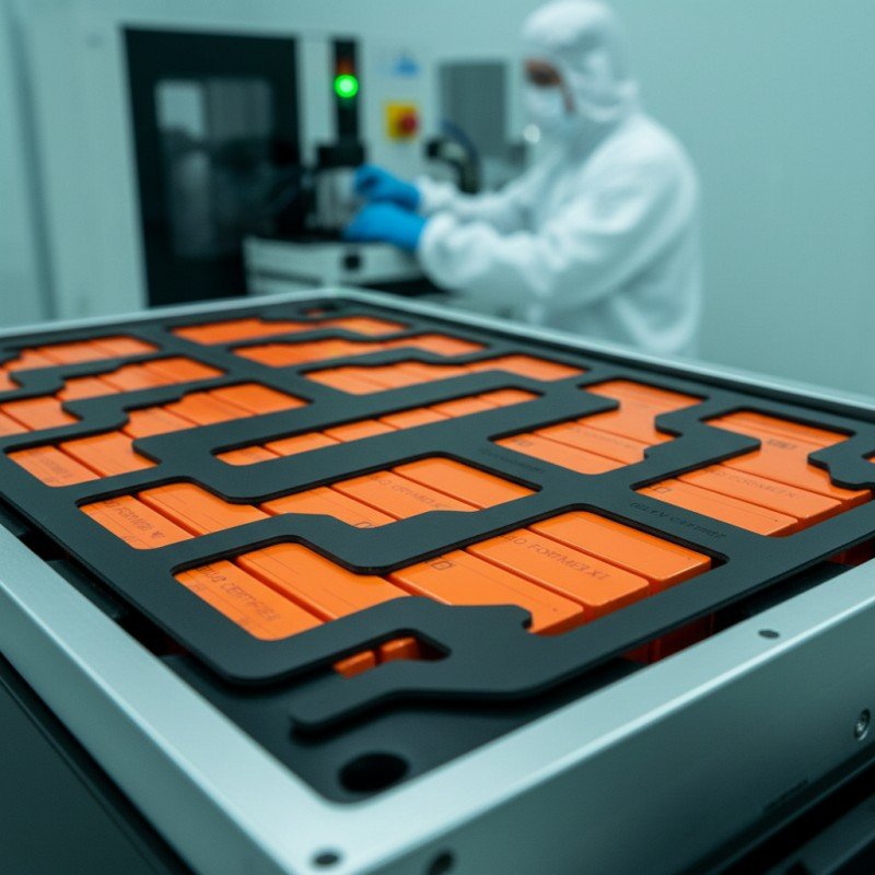
How Does Aerogel Slow Cell-to-Cell Heat Transfer in EVs?
Table of Contents
When two EV cells sit only millimeters apart, what prevents the heat from one failing cell from turning its neighbor into the next heat source? A cooling plate can remove routine operating heat, but it may not absorb a sudden, concentrated thermal-runaway pulse quickly enough. In that narrow gap, the outcome often depends on a thin barrier – and on whether that barrier still performs after compression, aging, lamination, die cutting, and assembly.
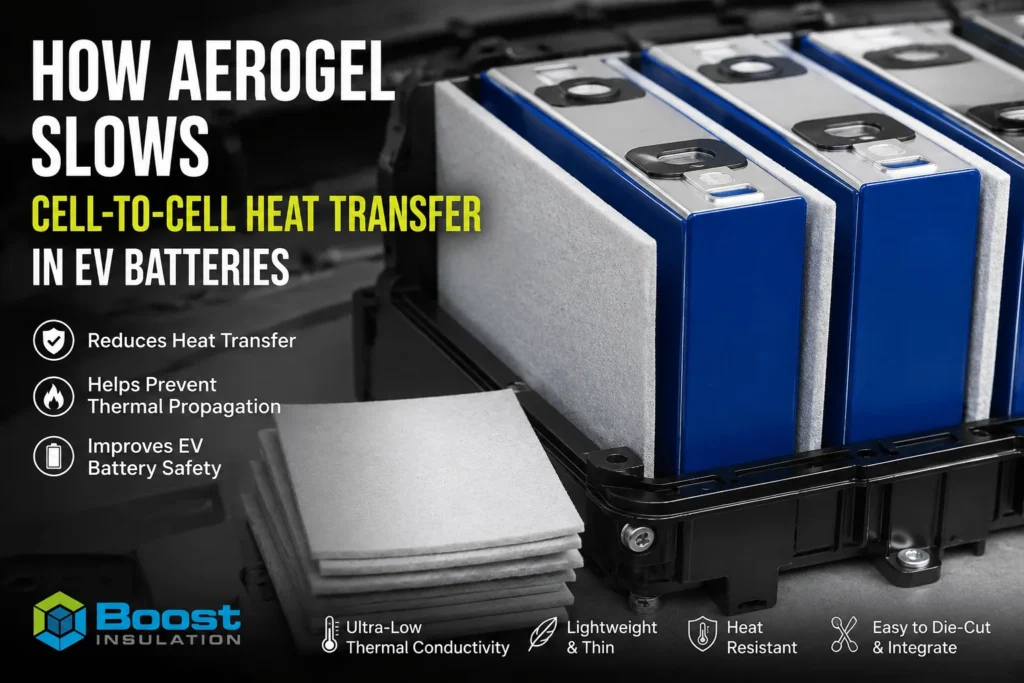
Aerogel slows cell-to-cell heat transfer in EVs by placing a very low-conductivity, heat-resistant layer between adjacent cells. Its nano porous structure restricts heat conduction through solids and trapped gas, suppresses internal convection, and lowers the heat flux reaching the neighboring cell. A correctly designed aerogel barrier also increases separation, reduces direct radiant exposure, and buys time before the next cell reaches a critical temperature. It does not make a battery pack immune to thermal runaway; results depend on thickness, coverage, compression, hot-gas paths, encapsulation, and module-level validation.
| Aerogel is effective because it reduces the rate of heat transfer, not because it removes heat. In an EV module, the design objective is usually to keep the adjacent cell below its runaway-triggering condition for a defined time and test scenario. |
Why Cell-to-Cell Heat Transfer Is a Pack-Level Risk
A lithium-ion cell in thermal runaway can release energy through several paths at once. The cell casing or pouch becomes extremely hot, internal reactions continue to generate heat, hot gases and particles may vent, nearby metal structures conduct energy, and exposed surfaces radiate toward adjacent components. The next cell does not need to touch flame to become dangerous. It only needs to absorb enough energy, for long enough, to cross a temperature and reaction threshold that it can no longer control.
This makes cell-to-cell propagation a race between heat input and heat rejection. The adjacent cell gains energy from the failed cell and surrounding structures while the cooling system, cell mass, end plates, busbars, enclosure, and ambient environment remove or redistribute part of that energy. A thermal barrier changes the race by reducing the rate at which energy enters the next cell. Even when it cannot block every path, lowering the dominant heat flux can extend the time to propagation, reduce the number of cells involved, or allow detection and safety systems to respond.
| Heat path | How heat reaches the next cell | What the barrier must address |
| Surface conduction | Heat flows from a hot cell face across the narrow inter-cell gap or through compressed layers. | Low through-thickness conductivity, adequate thickness, stable compression. |
| Metallic bypass | Frames, busbars, tabs, fasteners, end plates, and cooling hardware conduct around the pad. | Geometry and system design; an aerogel pad alone cannot interrupt every metal bridge. |
| Thermal radiation | The failed cell and hot structures radiate energy across gaps and openings. | Continuous coverage, suitable facing layers, controlled cutouts, and distance. |
| Hot gas and particles | Vented gas, flame, and ejecta travel through channels or damaged edges. | Vent-path management, erosion resistance, robust encapsulation, and pack architecture. |
| Engineering insight
The lowest room-temperature thermal-conductivity value is not automatically the best predictor of propagation performance. Heat can bypass the pad through metal, cutouts, vent paths, compressed edges, adhesive films, and structural contact points. |
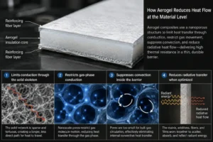
How Aerogel Reduces Heat Flow at the Material Level
Battery-grade aerogel barriers are usually reinforced composites rather than fragile monolithic aerogel blocks. A silica or ceramic-rich nano porous phase is supported by fibers, membranes, or other reinforcement so the material can be supplied as a thin sheet and converted into repeatable parts. The insulating effect comes primarily from the pore structure: the solid network is sparse, the gas phase is highly constrained, and large-scale convection cannot develop inside the material.
1. It limits conduction through the solid skeleton
Heat conduction through a solid depends on how continuous and conductive the solid path is. Aerogel contains a very small fraction of solid material arranged in a tortuous nanoscale network. The path available for heat to travel through the solid phase is therefore longer and less direct than in a dense polymer, rubber, ceramic plate, or metal component. Reinforcement improves mechanical handling, but it must be balanced carefully because every added fiber, film, or binder can create a more conductive path.
2. It restricts gas-phase conduction
Air is already less conductive than most solids, but gas molecules can still carry energy across ordinary foam cells and open gaps. In aerogel, pores are extremely small. Molecular motion is restricted, and gas-phase heat transfer is reduced. This is one reason a thin aerogel composite can provide useful thermal resistance where the available cell spacing is limited.
3. It suppresses convection inside the barrier
Convection requires enough connected space for gas to circulate. Aerogel pores are too small for meaningful bulk circulation, so internal convective heat transfer is effectively suppressed. This differs from a large air gap or coarse foam, where gas movement can contribute more to heat transfer, particularly when orientation and temperature gradients change.
4. It can reduce radiative transfer when the construction is optimized
At high temperatures, radiation becomes increasingly important. The aerogel matrix, opacifying additives, reinforcing fibers, and surface films all influence how much radiant energy crosses the barrier. A low-conductivity core with an inappropriate thin film, exposed opening, or reflective geometry may behave differently from the same core in a fully engineered laminate. Radiative performance is therefore a property of the construction, not just the word aerogel on a datasheet.
Thermal Resistance: Useful for Screening, Not Final Proof
For an initial comparison, engineers often look at thermal resistance, which increases with thickness and decreases with thermal conductivity. In simplified steady-state terms, doubling the thickness of the same material roughly doubles its thermal resistance. A material with one-tenth the conductivity can provide roughly ten times the steady-state resistance at the same thickness. This is a useful screening principle, but a thermal-runaway event is transient, highly nonuniform, and may include radiation, flame, vent gas, pressure, material damage, and changing conductivity.
The practical question is not simply, “What is the k-value?” It is: “What temperature-time curve does the adjacent cell experience in the actual stack-up?” A barrier may perform well for an early heat pulse and then degrade, shrink, char, delaminate, or be bypassed by a hot metal path. Conversely, a composite with a slightly higher room-temperature conductivity may deliver better part-level performance if it maintains coverage, survives compression, resists erosion, and controls the interface more reliably.
| Do not confuse insulation with cooling
Aerogel is intended to slow heat flow across a boundary. Thermal pads, gels, and cooling plates are intended to move routine heat toward a heat sink. A well-designed pack often needs both functions, located on different heat paths. |
What Happens During a Cell Failure
Aerogel does not act only at one temperature. Its role changes as the event develops. Understanding these stages helps the design team specify a realistic barrier instead of relying on a single material claim.
| Event stage | What occurs | Aerogel design objective |
| Normal operation | Cells generate manageable heat during charging and discharging. | The barrier should not create an unacceptable operating-temperature imbalance or interfere with the intended cooling path. |
| Abuse heating | A local fault or external heating raises one cell above normal limits. | The barrier reduces lateral heat leakage and gives controls more time to detect abnormal temperature behavior. |
| Thermal runaway onset | Self-heating accelerates and the failed cell surface temperature rises rapidly. | The low-conductivity layer slows the heat pulse reaching the adjacent cell face. |
| Venting and ejection | Hot gases, particles, and sometimes flame leave the cell. | The system must keep direct jets from bypassing or eroding the barrier; geometry is as important as core insulation. |
| Post-event soak | Hot components continue to radiate and conduct heat after the initial peak. | The barrier must retain enough integrity to control longer-duration heat exposure and prevent delayed propagation. |
Why the Finished Aerogel Part Matters More Than the Raw Sheet
An EV battery assembler installs a converted component, not a laboratory specimen. The core sheet may be laminated with PET film, coated, encapsulated, backed with pressure-sensitive adhesive, paired with a release liner, and die-cut around tabs, vents, sensors, fasteners, and busbars. Each of these decisions affects heat flow, flame behavior, mechanical integrity, and assembly repeatability.
Thickness after compression
The nominal sheet thickness is not necessarily the installed thickness. Cell stack pressure, module clamping, dimensional tolerance, and swelling can compress the barrier. Lower installed thickness reduces thermal resistance, while excessive local pressure may damage the porous structure or force contact at nearby bypass points. The drawing should therefore define both free thickness and the expected compressed condition.
Coverage and edge distance
A barrier only protects the area it covers. Large cutouts, narrow necks, misregistered holes, and short edges can concentrate heat flux. Near a vent, a gap that looks minor in CAD can become the direct path for hot gas or radiation. Coverage should follow the thermal map and likely failure paths rather than simply matching the visible cell face.
Encapsulation and facing films
Films can improve handling, contain dust, protect the core, and make automated assembly easier. They also change emissivity, flammability, shrinkage, dielectric behavior, and heat transfer. The finished laminate must be evaluated as a system. A core material rating should not be presented as proof that every laminated construction has the same performance.
Adhesive and release-liner design
Adhesive may be needed for positioning, but a full-surface adhesive layer can create an additional heat path and may change flame behavior. Pattern coating or selective adhesive placement may reduce unnecessary thermal bridging. Peel tabs, split liners, and assembly sequence also affect whether operators position the part correctly without damaging it.
Dust, edges, and mechanical durability
Unprotected aerogel edges can release particles during cutting, transport, or assembly. Edge sealing, clean cutting, protective skins, extraction, packaging, and inspection are therefore part of the product design. A thermally excellent barrier that sheds material, tears at a notch, or arrives warped may not be suitable for a repeatable battery line.
Cell Format Changes the Heat-Transfer Problem
| Cell format | Main heat-transfer characteristics | Typical design response |
| Prismatic cells | Large flat faces create a broad conduction and radiation interface. Cell swelling and stack pressure can be significant. | Full-face or targeted face barriers, controlled compression, vent clearance, and edge coverage. |
| Pouch cells | Thin layers are stacked closely; heat spreads differently in-plane and through-plane. Expansion management is central. | Flexible low-profile barriers combined with a separate compression layer where required. |
| Cylindrical cells | Curved surfaces create point or line contacts; heat may travel through holders, busbars, potting, and air channels. | Segmented pads, wraps, inter-row barriers, vent-path control, and careful treatment of structural bridges. |
The same aerogel grade cannot be assumed to deliver the same result in all three formats. A flat coupon test may represent a prismatic interface reasonably well but fail to capture a cylindrical module with multiple gas channels and conductive holders. The validation fixture must reproduce the relevant contact geometry, clamping, vent orientation, and surrounding materials.
How Aerogel Works With PC Insulation and Silicone Foam
The best cell-to-cell barrier is often a material system rather than a single sheet. Aerogel provides high thermal resistance in limited space, while other materials solve structural, electrical, compression, and assembly problems that aerogel does not solve efficiently by itself.
| Material | Primary role | Strength | Design caution |
| Aerogel composite | Slow through-thickness heat flow and propagation | Very low conductivity; thin thermal barrier | Fragility, dust, compression sensitivity, edge protection |
| Flame-retardant PC sheet | Electrical and structural isolation | Puncture resistance, dimensional stability, clean die cutting | Not a substitute for a high-temperature thermal barrier |
| Silicone foam | Gap filling, sealing, cushioning, and pressure control | Resilience, tolerance absorption, vibration damping | Usually higher thermal conductivity than aerogel; compression data is critical |
| Mica | High-temperature electrical and flame barrier | Thermal stability and dielectric performance | Brittleness and edge cracking; may need lamination or support |
One practical architecture uses a thin aerogel layer for heat resistance, a flame-retardant polycarbonate layer for puncture and electrical isolation, and localized silicone foam for tolerance absorption or sealing. Another uses aerogel between cells and mica near a vent or pack cover where direct flame and high-temperature electrical isolation dominate. These are design examples, not universal recipes. The final stack-up should be selected from the pack heat map, electrical clearances, cell movement, vent direction, and validation target.
Eight Parameters That Determine Real Performance
- Thermal conductivity across temperature: Request data across a relevant temperature range when available. Room-temperature values alone may not represent a runaway exposure.
- Installed thickness: Specify free thickness, tolerance, compressed thickness, and the stack pressure used to determine it.
- Thermal diffusivity and heat capacity: These influence the transient temperature response, not only the steady-state resistance.
- High-temperature integrity: Assess shrinkage, embrittlement, cracking, burn-through, erosion, and retention after exposure.
- Electrical properties: Define dielectric strength, insulation resistance, creepage, clearance, and contamination conditions for the finished part.
- Flammability of the complete construction: Verify the exact thickness, skin, adhesive, color, and laminate. UL 94 is a material flammability classification, not a thermal-propagation certification.
- Mechanical and environmental durability: Include compression set, vibration, thermal cycling, humidity, coolant or electrolyte exposure, and aging where relevant.
- Manufacturing capability: Confirm tolerances, edge sealing, cleanliness, registration, traceability, packaging, and change control.
Industry Insight: Buyers Are Purchasing Time, Not Just a Low k-Value
Modern EV packs are becoming more integrated. Larger-format cells, cell-to-pack architectures, thinner module structures, and higher packaging efficiency reduce unused space but can also reduce the passive thermal separation between cells. Fast charging and longer service life add another complication: the pack must remain safe not only when new, but after cycling, calendar aging, mechanical stress, and manufacturing variation.
This changes how technically mature customers evaluate an aerogel barrier. The purchasing target is increasingly expressed as a system outcome: keep the adjacent cell below a defined temperature, delay propagation for a specified period, prevent flame exit into a protected zone, or meet a vehicle-level test requirement. A datasheet is still required, but it is the start of the engineering discussion rather than the conclusion.
UNECE Regulation No. 100 Revision 3 includes thermal-propagation-related requirements for rechargeable electrical energy storage systems. It does not prescribe aerogel, mica, or any specific barrier material. The pack manufacturer remains responsible for showing that the complete system meets the applicable requirements. This is why suppliers should be precise, aerogel can reduce heat transfer and may prevent propagation in a validated design, but no converted pad should be marketed as an automatic guarantee of pack compliance.
A second market shift is the move toward hybrid components. Engineers increasingly ask converters to combine insulation, flame resistance, dielectric protection, compression management, and assembly aids into a controlled multilayer part. This reduces part count and line complexity, but it also raises the importance of DFM, laminate qualification, dimensional capability, and formal change control. The converter is no longer only cutting a shape; it is helping preserve the intended physics from material selection through mass production.
Precision Die Cutting: Where Thermal Design Becomes a Production Part
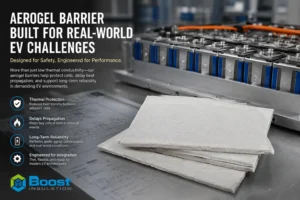
Cell-to-cell aerogel parts often appear simple, but small geometry decisions can change both thermal performance and assembly yield. The die-cutting process must protect the low-density core, maintain critical coverage, register multiple layers, and produce a clean component that survives handling.
- Use a drawing that identifies critical-to-function dimensions separately from general outline tolerances.
- Define keep-out zones around cell vents, terminals, sensors, weld areas, and adhesive squeeze-out paths.
- Specify whether cut edges require sealing, film overhang, folded encapsulation, or exposed core.
- Evaluate whether a full-surface adhesive, perimeter adhesive, patterned adhesive, or mechanical retention is appropriate.
- Control registration among the aerogel core, protective films, adhesive zones, pull tabs, and release-liner splits.
- Specify cleanliness, particle limits, inspection method, packaging orientation, and lot traceability.
- Use early prototypes to verify installation force, liner removal, visual alignment, compression, and interference with neighboring parts.
| DFM question to ask before tooling
Which dimensions control thermal coverage, and which only control assembly clearance? Separating these categories can improve both capability and cost without weakening the barrier function. |
A Practical Validation Ladder
A reliable program validates the material, the converted part, and the battery system at progressively higher levels. Skipping directly from a supplier datasheet to a pack test can make failure analysis expensive. Stopping at coupon tests can create false confidence.
| Level | Typical evidence | Decision question |
| 1. Material screening | Conductivity, thickness, density, high-temperature behavior, electrical properties, flammability, mechanical data. | Does the candidate material meet the initial envelope? |
| 2. Laminate and part tests | Actual film, adhesive, edge seal, compressed thickness, peel strength, dimensional stability, cleanliness. | Did conversion change the intended properties? |
| 3. Thermal fixture test | Representative cell faces or heaters, contact pressure, gaps, metal bypasses, thermocouples, heat-flux or temperature-time data. | Does the part reduce heat transfer in the actual interface? |
| 4. Module propagation test | Real cells, state of charge, aging condition, trigger method, vent direction, cooling state, enclosure and instrumentation. | Does the architecture delay or prevent propagation under the defined scenario? |
| 5. Pack and vehicle validation | Applicable regulatory and OEM test plans, warning strategy, containment, venting, electrical isolation and post-event safety. | Does the complete system meet its safety requirement? |
The pass criterion should be written before testing. Useful criteria include the maximum adjacent-cell surface temperature, time to a defined threshold, no propagation within an observation window, no flame in a protected area, maintained electrical isolation, and acceptable post-test enclosure condition. Without a pre-defined criterion, a visually dramatic test can still produce an ambiguous engineering decision.
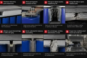
Common Reasons Aerogel Barriers Underperform
- The selected thickness is reduced too far by pack compression.
- A metal bracket, busbar, end plate, or fastener bypasses the insulated cell face.
- Vent gas or ejecta reaches the neighboring cell through a cutout or edge gap.
- The facing film shrinks, melts, or opens a direct radiation path.
- Adhesive creates a continuous thermal bridge or loses position during aging.
- The barrier is undersized because the drawing follows nominal cell dimensions instead of tolerance and swelling limits.
- Die-cut damage, wrinkles, delamination, or dust compromise the installed part.
- Coupon test conditions do not reproduce state of charge, cell aging, contact pressure, orientation, cooling, or enclosure geometry.
What to Include in an Aerogel RFQ
A precise RFQ allows a converter to recommend the correct construction and quote tooling, samples, and production more accurately. For a cell-to-cell aerogel component, provide the following information whenever it is available:
- Cell format, chemistry, dimensions, state-of-charge range, and module architecture.
- The design objective: routine thermal isolation, propagation delay, electrical isolation, flame shielding, or a combination.
- CAD or PDF drawing with critical dimensions, cutouts, vent direction, adhesive zones, pull tabs, and liner splits.
- Available gap, nominal thickness, tolerance, expected compression, clamping force, and cell-swelling allowance.
- Target thermal-conductivity range and temperature-time or propagation requirement.
- Electrical, flammability, chemical, humidity, thermal-cycle, vibration, and aging requirements.
- Prototype quantity, annual volume, inspection plan, packaging, traceability, PPAP/APQP, and change-control expectations.
How Boost Insulation Supports Cell-to-Cell Barrier Projects
Boost Insulation supports custom EV battery insulation parts from material selection and laminate design through precision die cutting and prototype verification. For cell-to-cell barriers, the engineering discussion can include aerogel core selection, protective-film construction, pressure-sensitive adhesive pattern, edge treatment, pull-tab design, dimensional tolerance, clean packaging, and integration with flame-retardant polycarbonate insulation or silicone foam components.
The most productive starting point is a module drawing and a clear test objective. From that information, the part can be reviewed for thermal coverage, likely bypass paths, compression, manufacturability, assembly sequence, and inspection. This approach helps avoid a common sourcing failure: selecting a promising raw material and discovering too late that the converted part cannot be installed consistently or does not represent the tested construction.
| Request a technical review
Send your cell layout, available gap, compression condition, vent direction, required tests, and annual volume. Boost Insulation can review the stack-up and prepare a custom die-cut sample and quotation for engineering validation. |
Frequently Asked Questions
Does aerogel completely stop heat transfer between cells?
No. All real materials transfer some heat. Aerogel greatly reduces the rate of heat transfer when it is correctly selected and installed. Whether propagation is prevented depends on the complete heat load, thickness, coverage, bypass paths, cell condition, cooling, and system design.
Is a lower thermal-conductivity value always better?
It is beneficial for through-thickness resistance, but it is not the only selection criterion. High-temperature integrity, compression, dimensional stability, coverage, encapsulation, electrical properties, dust control, and manufacturability can dominate part-level performance.
Can aerogel replace the battery cooling system?
No. Aerogel is an insulator. A cooling plate, thermal interface material, or coolant loop moves routine heat to a heat sink. Aerogel is placed where the design wants to slow lateral or upward heat flow, especially during abnormal conditions.
How thick should a cell-to-cell aerogel pad be?
There is no universal thickness. The correct value depends on the available gap, conductivity, installed compression, heat pulse, cell format, target delay, and alternative heat paths. Thickness should be selected through thermal modeling and representative testing.
Does adhesive reduce aerogel performance?
It can. Adhesive adds another material layer and may form a more conductive path, particularly when applied across the full surface. It can also improve position and assembly consistency. Pattern, thickness, flame behavior, aging, and peel strength should be evaluated in the finished part.
Is UL94 V-0 proof that a barrier stops thermal propagation?
No. UL 94 classifies the flammability behavior of a material under specified small-scale test conditions. It is useful evidence for material selection but is not a battery module thermal-propagation test or a guarantee of pack compliance.
Can aerogel be combined with PC sheet or silicone foam?
Yes. A PC layer may provide puncture-resistant electrical isolation, while silicone foam can manage tolerance, sealing, and compression. The combined construction should be evaluated for total thickness, heat transfer, flame behavior, durability, and assembly.
What is the fastest way to get an accurate quotation?
Provide the 2D drawing or CAD file, stack-up, target thickness, adhesive and liner requirements, critical tolerances, validation requirements, prototype quantity, and estimated annual volume. Include cell pressure and vent-path information when the part is used between cells.
Final Answer
Aerogel slows cell-to-cell heat transfer in EVs because its nanopores structure creates high thermal resistance in a very thin, lightweight layer. It restricts solid and gas conduction, prevents internal convection, and can reduce radiative exposure when the full construction is engineered correctly. In a battery module, this lowers the heat flux reaching the neighboring cell and can provide valuable time before that cell reaches a critical condition.
The effective product, however, is not the raw aerogel sheet. It is the installed, compressed, laminated, die-cut barrier working together with cell spacing, cooling, venting, structural parts, electrical insulation, and safety controls. The correct selection process therefore combines material data, DFM, part-level testing, and representative module or pack validation.
| Need a Custom Aerogel Cell Barrier?
Send your drawing, cell spacing, compression condition, target test, and annual volume for a material and DFM review. |
Technical References
- UNECE Regulation No. 100, Revision 3: https://unece.org/transport/documents/2022/03/standards/regulation-no-100-rev3 – Vehicle electrical powertrain and REESS safety requirements, including thermal-propagation provisions.
- UL 94 – Tests for Flammability of Plastic Materials: https://www.shopulstandards.com/ProductDetail.aspx?productId=UL94_7_S_20230228 – Scope and role of small-scale polymer flammability classification.
- Wong et al., Energy, 2024: https://www.sciencedirect.com/science/article/abs/pii/S0360544224021273 – Experimental evaluation of nanofiber aerogel for mitigating thermal propagation in a high-energy-density lithium-ion battery module.
- Han et al., Fire, 2024: https://www.mdpi.com/2571-6255/7/4/119 – Experimental study of thermal-runaway propagation in cycling-aged lithium-ion battery modules.
Related Posts:
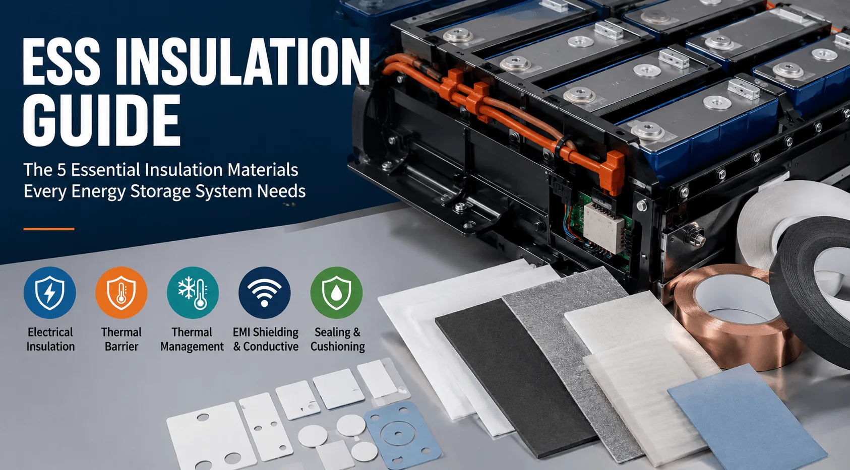
What Insulation Does an Energy Storage System Need?
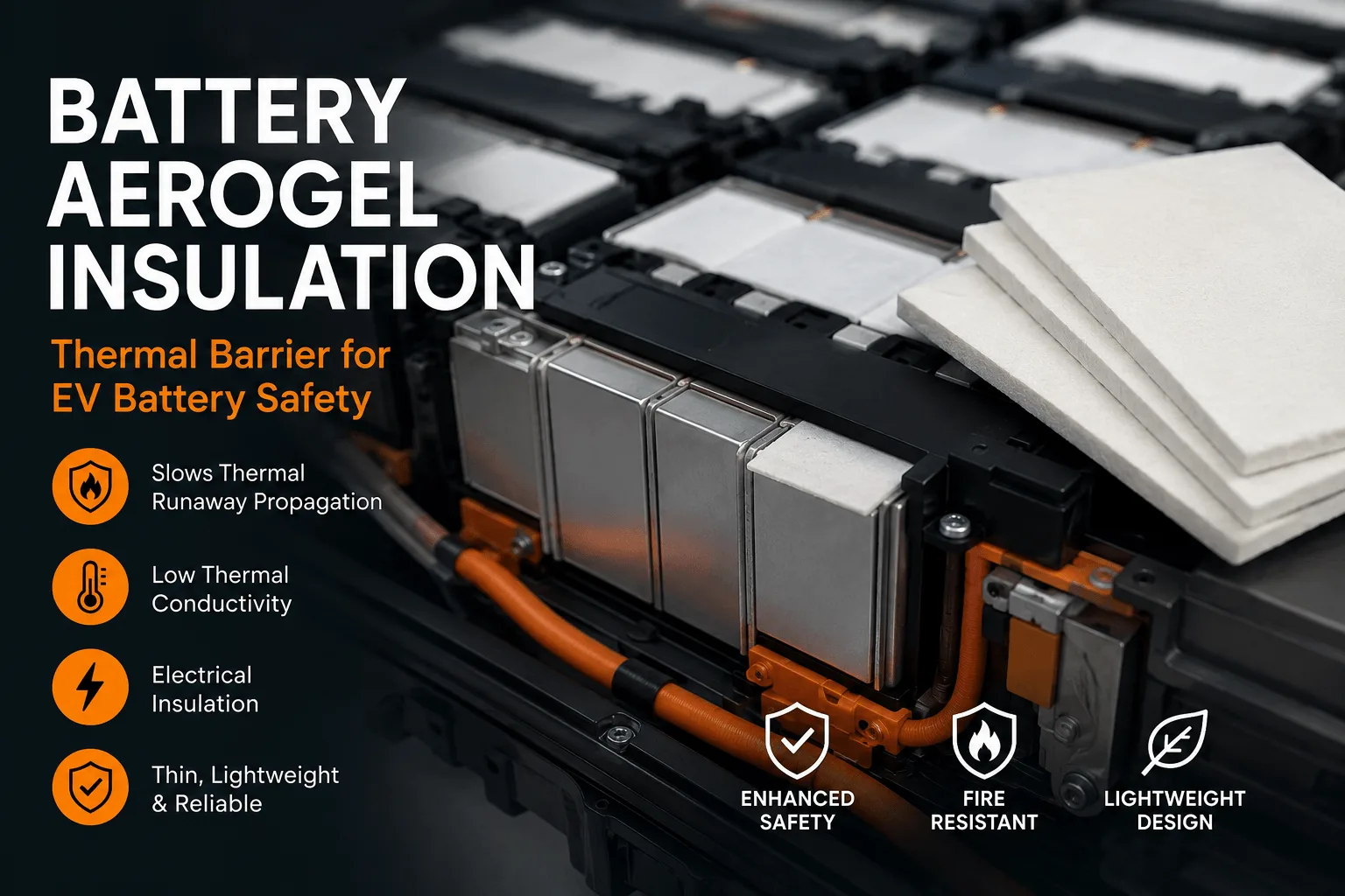
What Is Battery Aerogel Insulation for EV Battery Packs?
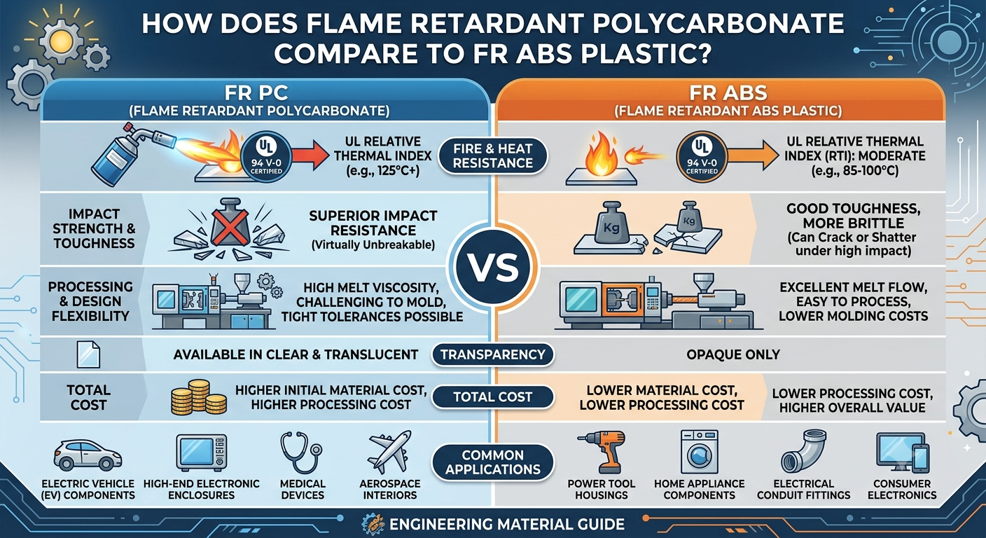
How Does Flame Retardant Polycarbonate Compare to FR ABS Plastic?
How Do You Choose a Flame Retardant PC Supplier?
How Does a Mica Insulation Sheet Protect Battery Pack Lids?
How Can You Prevent UV Yellowing in FR Polycarbonate?
 betty wong