
FR4 vs PC for EV Battery Mounting Plates: How to Choose?
Table of Contents
An EV battery contactor or fuse may require an electrically insulating mounting plate, but choosing between FR4 and polycarbonate is not simply a competition in stiffness. The plate must support actual hardware, preserve terminal-to-metal separation, tolerate fastener loads, and maintain position during vibration and temperature changes. A material that works as a protective cover may be unsuitable as a heavily loaded mounting substrate. Conversely, a rigid laminate may create avoidable weight, space, or processing constraints for a light-duty part. The decision starts with the installed mounting function.
⚑ QUICK ANSWER
Key Takeaways for Engineers
- Compare a particular FR4 laminate grade against a particular PC grade and form, not two generic material names.
- Separate mounting plates that actually carry hardware loads from insulating covers that mainly locate or shield components.
- Examine continuous load and temperature together; room-temperature short-term stiffness does not establish long-term positional stability.
- Treat fasteners, washers, nearby busbars, and support conditions as parts of both the mechanical and electrical design.
- Select the manufacturing route alongside geometry, then validate finished parts in their installed assembly.
What Does an EV Battery Mounting Plate Need to Do?
A mounting plate in a battery disconnect unit (BDU), high-voltage junction box (HVJB), or pack electrical compartment might carry a contactor, a fuse assembly, a terminal-related part, or a local busbar support. That plate may also separate the mounted component from a metal enclosure. These are different duties: a load-carrying substrate transfers forces into its supports; a secondary locating panel positions parts; a protective cover mainly shields an exposed electrical region.
Start with the component manufacturer’s mounting instructions and the full installed assembly. Identify where weight enters the plate, where busbar or cable forces act, what supports the plate, and what movement is permissible without reducing electrical spacing. Neither material should be presumed a crash-load member merely because it appears rigid.
FR4 vs PC: What Is the Main Difference for Mounting Plates?
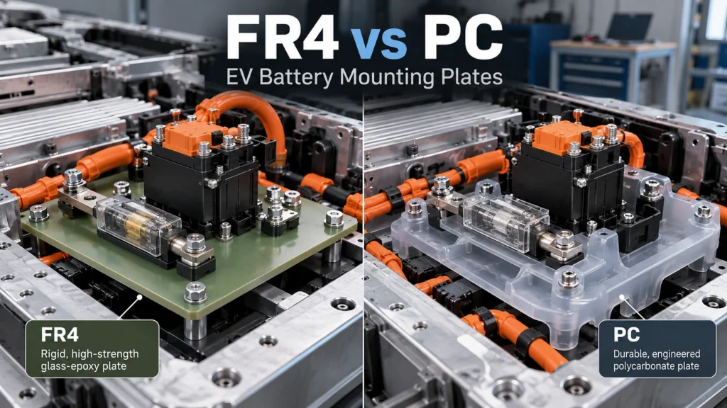
FR4 is a glass-fabric-reinforced epoxy thermoset laminate (see Boost’s rigid FR4 battery insulation overview for broader applications). PC is a thermoplastic family supplied as films, sheets, and molded compounds (see rigid PC insulation in battery modules for protective-panel applications), including unfilled, flame-retardant, and reinforced formulations. A specific FR4 grade may provide useful board-like support, whereas suitable PC products can offer a practical balance of toughness, conformability, and shaped-part processing. Grade-specific datasheets govern design.[1][2][3]
Table 1 — FR4 vs PC Mounting-Plate Selection
| Design requirement | FR4 review | PC review | Engineering decision |
| Solid electrical insulation | Check laminate grade, thickness, condition and interfaces | Check exact PC grade, form and relevant thickness | Validate installed dielectric system |
| Board-like stiffness | Useful candidate for rigid flat support | Depends on grade, thickness and geometry | Compare allowable deflection at real span |
| Localized impact | Check notch, hole and laminate damage behavior | Check toughness and local stress of specified formulation | Test assembled impact and retention |
| Sustained load | Check laminate creep/aging and bearing interface | Check time-dependent creep and stress relaxation | Compare service-duration deformation |
| Bolted mounting | Examine drilled-hole quality, bearing and laminate damage | Examine bearing deformation, cracking and relaxation | Review washer and insert architecture |
| Temperature cycling | Check orientation and laminate properties | Check grade-dependent modulus, expansion and residual stress | Measure installed alignment after cycling |
| Flat CNC plate | Common route for holes, profiles and slots | Also machinable depending on grade and thickness | Choose by tolerances, edge quality and volume |
| Thin formed shield | Less typical for thermoset laminate | Possible with suitable PC film/sheet and process | Verify formability and stress |
How Do Mechanical Loads Affect FR4 vs PC Selection?
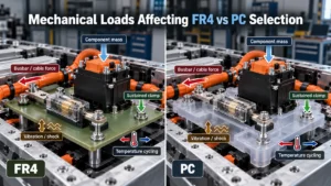
A contactor’s mass is only one load input. Assembly clamping, busbar misalignment, cable strain, vibration, shock, and thermal expansion can impose forces through different interfaces. Document both their directions and where they enter the plate. Likewise, a panel intended primarily as an insulating shield may experience only limited service loading.
Table 2 — Mechanical Load Case and Material Review
| Load or condition | Design risk | FR4 review | PC review | Evidence required |
| Component mass | Sag or fastener moment | Span and flexural response | Deflection and sustained loading | Installed displacement |
| Sustained clamp | Local bearing damage or relaxation | Hole integrity and pressure spread | Time-dependent compression and creep | Joint retention after exposure |
| Busbar/cable force | Warped support, terminal offset | Load path and fixture points | Local bending and attachment design | Loaded assembly fit |
| Vibration/shock | Relative movement or hole damage | Laminate and joint response | Notch/impact and joint response | Relevant vibration/shock checks |
| Temperature cycling | Preload and location drift | Laminate/metal expansion interactions | PC/metal expansion and stress | Before/after geometry |
How Do Bending Stiffness and Unsupported Span Change the Choice?
Bending stiffness is not the same as strength or toughness. For simplified constant-width plate bending, stiffness depends strongly on thickness as well as elastic modulus, while deflection is highly sensitive to unsupported span and boundary conditions. The real battery mounting plate often has holes, cutouts, multiple restraints, and off-center loads. Those features can dominate the idealized plate behavior. Engineers should not infer an installed deflection from a generic datasheet modulus alone.
If a long unsupported section carries a heavy device, FR4 may deserve early investigation because a suitable glass-epoxy laminate can offer board-like rigidity. Yet shortening the span, relocating a support, or adding a bracket may be more effective than changing PC to FR4. A relatively short and well-supported PC mounting part can meet a given movement requirement without needing to match the standalone stiffness of a thicker FR4 plate.
How Do Continuous Loading and Creep Affect Mounting Plates?
Creep is time-dependent deformation under sustained stress; stress relaxation is a change in stress under constrained deformation. Both concepts matter around bolted interfaces and long-duration supported loads. A PC sheet that initially holds a contactor position can behave differently after sustained loading at its actual operating temperature. FR4 also requires grade-specific long-term and environmental assessment; it is incorrect to assert that FR4 cannot creep or age.
The critical question is not whether a material deflects once, but whether it keeps the component and fastener geometry within limits over service life. For PC, request relevant long-term mechanical information for the identified grade and processing form. For FR4, account for laminate direction, resin system, interfaces, and long-term exposures. Where suitable data are absent, conservative prototype testing may be necessary rather than assuming a short-term flexural test answers the service-life question.
How Do Fasteners and Washer Loads Affect FR4 and PC?
Bolt tightening creates a joint with uncertain clamp load unless its full torque/preload relationship and assembly controls are established. Torque is not a guaranteed load value. The washer footprint distributes pressure but also defines a contact region near a hole and, because it is often conductive, may affect HV spacing. Engineers must review washer contact area, hole diameter and position, edge distance, metal inserts or spacers, and the likely temperature-dependent joint behavior.
For FR4, evaluate drilled-hole integrity, bearing support, local cracking or delamination, and compression near the laminate face. For PC, evaluate local deformation, hole elongation, stress concentration, and relaxation during sustained clamping. Neither material automatically electrically isolates a metal bolt from an energized conductor. A shoulder washer or insulating sleeve can help with a defined interface only when its material, engagement length, tolerance, electrical geometry, and loading have been verified.
Table 3 — Fastener, Hole and Mounting Interfaces
| Feature | FR4 consideration | PC consideration | DFM / validation question |
| Through-bolt and washer | Local laminate bearing and drilled edge | Contact pressure and time-dependent deformation | Does the clamp load remain acceptable? |
| Metal insert or standoff | Local section and electrical path | Insert retention and local stress | What potential does the metal carry? |
| Mounting-hole pattern | Position accuracy and laminate breakout | Hole distortion and notch behavior | Can the assembly locate repeatably? |
| Large cutout beside hole | Remaining web and local stiffness | Remaining web and stress concentration | What is the worst loaded geometry? |
| Insulating bushing | Fit, hole wall and edge integrity | Fit, compression and material compatibility | Is electrical separation maintained after aging? |
| Washer-to-terminal gap | Actual fastener potential and geometry | Same system-level requirement | Are creepage and clearance preserved? |
What Do Vibration and Impact Mean for Material Selection?
Vibration exposes joints to cyclic motion, while a shock event can involve abrupt acceleration and local contact. These are not synonyms for material impact strength. A tough PC grade might tolerate handling or some contact events well, yet a mounting plate could still lose positioning through excessive flexure or a joint that relaxes. A stiff FR4 construction might hold initial alignment, yet its machined hole geometry and local load transfer still need validation for the prescribed vibration environment.
Assess the entire assembly: fasteners, washers, busbars, contactor housing, fuse holder, and supporting metal. Confirm that relative motion does not create an unintended electrical contact or reduce required separation. Component-specific mounting recommendations and the OEM validation plan should determine the test conditions; no universal FR4-versus-PC vibration ranking is justified.
How Do Temperature and Thermal Expansion Affect the Assembly?
Material stiffness, long-term deformation, and dimensional behavior can change with temperature. A device mounted close to a fuse connection or resistive joint may encounter a more demanding local temperature than the nominal pack-air value. The chosen FR4 or PC grade must therefore be screened against the expected normal and abnormal operating envelope, not a generalized continuous-use temperature number.
Thermal expansion also occurs across a multi-material assembly: laminate or polymer plate, aluminum enclosure, copper or aluminum busbar, metal fasteners, and component housing. Differential movement can change hole alignment, local contact pressure, terminal forces, or clearance. FR4 laminates may have direction-dependent properties; PC sheet behavior depends on formulation and processing history. Do not compare one CTE entry from an FR4 datasheet with a different PC test condition and imply a precise finished-assembly outcome.
Can Both FR4 and PC Provide High-Voltage Electrical Insulation?
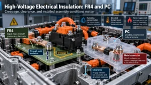
Yes, when the specific grade and finished design satisfy the required electrical conditions. Neither is automatically a complete insulation system. Solid dielectric performance through the material must be evaluated separately from creepage along an insulating surface and clearance through air. A metal mounting screw can redefine the shortest relevant path even when the sheet itself remains intact. IEC 60664-1 provides an insulation-coordination framework within its stated scope; applicable vehicle/OEM/component requirements still govern the battery design.
A comparison based only on supplier dielectric strength is insufficient. Test specimen thickness, electrode arrangement, conditioning, grade, surface contamination, machining, and installed fasteners can differ from the final component. Multiplying a nominal dielectric-strength number by plate thickness is not a guaranteed finished-part breakdown or working-voltage rating. CTI, when applicable to the chosen coordination method, does not itself specify the required creepage distance.
Table 4 — Electrical and Environmental Decision Gates
| Requirement | FR4 assessment | PC assessment | Required evidence |
| Through-solid insulation | Grade, thickness, laminate condition | Grade, thickness, processing state | Defined withstand and insulation tests |
| Creepage | Surface path and exposed hardware | Surface path and exposed hardware | Installed geometry and surface condition |
| Clearance | Busbar, terminal and fastener locations | Same full-assembly geometry | Worst relevant air-gap check |
| Contamination/humidity | Surface condition and machined residues | Surface condition and processing residues | Environmental evaluation |
| Elevated temperature | Laminate grade and interfaces | Grade-dependent mechanical/electrical behavior | Temperature-conditioned testing |
| Flame requirement | Verify exact rating and thickness | Verify exact rating and thickness | Appropriate material/end-product evidence |
Does Material Thickness Determine the Winner?
No. Equal thickness does not mean equal stiffness, load capability, dielectric qualification, or manufacturability. Conversely, an FR4 plate and a differently sized PC part can meet the same functional requirement using different support patterns, thicknesses, or formed features. Thickness affects space, component stack-up, material use, weight, CNC work, and polymer-forming feasibility. Boost also maintains a dedicated PC insulation thickness guide. Its selection must follow actual electrical, mechanical, and assembly constraints.
The thickness of solid insulation is not creepage or clearance. An otherwise thicker mounting plate can still expose a nearby fastener head or terminal to an inadequate surface or air path. This article treats thickness as one comparative design variable, not as a universal sizing guide.
How Do Geometry and Manufacturing Route Influence the Choice?
A flat mounting plate with accurate drilled holes, slots, and stable locating datums can be a natural candidate for CNC-machined FR4. CNC can also machine PC, particularly for prototypes or certain thicker profiles. For appropriate PC film or sheet grades, die cutting can offer a practical production route for two-dimensional profiles; formed or molded features may solve a protective or positioning requirement differently. These choices depend on grade, thickness, design maturity, volume, tooling, and geometry rather than a blanket cost ranking.
FR4 routing and drilling require review of reinforcement, tool access, edge chipping, delamination, exposed fibers, hole location, and removal of machining debris. PC machining or converting requires attention to burrs, residual stress, stress whitening or cracking where relevant, masking, and handling. Forming is not universally available for every flame-retardant or reinforced PC grade. A manufacturable material is one whose selected form can deliver the required geometry, tolerances, edge quality, and inspection process.
Table 5 — CNC Machining, Die Cutting and Forming
| Manufacturing need | FR4 route | PC route | Selection question |
| Flat drilled mounting plate | CNC drilling/routing candidate | CNC drilling/routing candidate | Which grade and geometry pass loaded fit tests? |
| Intricate 2D outline | CNC profile review and edge control | CNC or grade/thickness-suitable die cutting | What edge and tolerance quality is needed? |
| Formed lip or protective return | Usually requires alternative construction | Possible for suitable formable PC grades | Does forming preserve fit and properties? |
| Rapid design iterations | CNC prototype strategy | CNC/other prototype strategy | What tooling commitment is justified? |
| High-repeatability production | Control material, fixture and cut quality | Control cutting, forming or molding process | Which process fits the approved drawing? |
| Adhesive/masking integration | Review cleanliness and surface preparation | Review liner, registration and residual stress | Can assembly remain dimensionally stable? |
FR4 vs PC for Common EV Battery Mounting Scenarios
Table 6 — Application-Based Material Selection Matrix
| EV mounting scenario | Dominant requirement | Material-selection logic | Validation priority |
| Rigid contactor substrate | Mounted mass, terminal position | Screen FR4 stiffness; assess PC if geometry/support permits | Loaded deflection and fastening |
| Fuse support panel | Connection loads and local heat | Check both grades against actual thermal/interface requirements | Temperature and terminal fit |
| Light-duty locating plate | Position without large structural load | PC or FR4 may work; assess part form | Assembly repeatability |
| Large unsupported panel | Long-span deflection | Assess FR4, thicker/formed PC, or added supports | Full-span movement |
| Protective cover with tabs | Handling and shaped geometry | Consider suitable PC converting/forming route | Retention and electrical coverage |
| Plate with dense cutouts | Local sections and hole integrity | Reconsider layout in either material | Hole/edge damage and stiffness |
| Repeated thermal cycling | Differential movement | Compare specific grades and joint architecture | Post-cycle clearance |
| Sustained fastener clamping | Local bearing and creep/relaxation | Compare time-dependent interface behavior | Clamp retention and distortion |
When Should Engineers Prefer FR4, PC, or Neither?
Consider FR4 when the mounting role requires a flat, board-like insulating substrate, precise CNC-machined locating features, and stiffness that helps preserve high-voltage component geometry. The specific laminate’s load, environmental, and electrical suitability still requires verification. This is an application-based preference, not a statement that FR4 is qualified for every load-bearing or automotive structural duty.
Consider PC when a supported mounting or protective component benefits from toughness, shaped coverage, handling behavior, or a die-cut or formed sheet route. The selected grade must withstand service loading and temperature without unacceptable creep, bearing deformation, or positional change. Sheet PC, molded PC, and reinforced PC should not be conflated.
Reconsider both when the required load is beyond the validated plate architecture, severe heat or fault-event exposure dominates, electrical spacing cannot be achieved in the available geometry, or a separate metal structural carrier with dedicated insulating barriers would be more appropriate. Mica or other high-temperature insulators may address a thermal-facing function, but are not automatically interchangeable structural mounting boards. A grade-specific UL 94 classification does not certify a finished battery mounting assembly against thermal runaway.
How Should Engineers Validate the Final Mounting Plate?
Begin with candidate-grade documentation and a controlled drawing. Evaluate prototype material identification, thickness, hole pattern, datums, critical clearances, edges, and cleanliness. Install the real high-voltage component or a validated representative mass/fixture. Measure deflection and terminal alignment under relevant static, clamped, and dynamic conditions. Then review the electrical insulation paths using actual fasteners, washers, busbars, enclosure metal, and assembled tolerances.
A relevant plan can include sustained-load exposure, vibration/shock, thermal cycling, humidity, electrical withstand, insulation resistance, and post-test dimensional inspection. Not every project uses every test; acceptance criteria must come from the responsible system engineering team. Record changes in clearance, clamp retention, hole condition, or mounting position, rather than reporting only whether a raw coupon passed a materials test.
Common FR4 vs PC Mounting-Plate Selection Mistakes
- Choose FR4 because it feels stiffer: define permissible installed deflection and verify loads before deciding.
- Choose PC solely for toughness: confirm that permanent deformation and fastening still meet the requirement.
- Compare generic family values: identify the grade, supplier, form, and relevant test conditions.
- Ignore component mass: transfer actual mounting loads into the design model.
- Ignore unsupported span: check real support points and panel movement.
- Skip allowable deflection: define electrical and mechanical movement limits at critical features.
- Ignore creep: assess sustained load together with temperature and service duration.
- Ignore washers and inserts: review local bearing, hardware potential, and retention.
- Use only room-temperature data: verify relevant operating and aging conditions.
- Neglect thermal expansion: examine constrained movement among metals and insulating parts.
- Choose by dielectric strength alone: check solid, surface, and air insulation paths.
- Assume thickness fixes creepage or clearance: review installed conductor geometry.
- Compare equal thickness as equal performance: evaluate equivalent functional designs.
- Ignore process-created defects: inspect machined/formed edges and local stress.
- Equate a datasheet with approval: test and document the finished mounting assembly.
Six Industry Insights for Mounting-Plate Design
Insight 1 — Start with mounting function, not generic rankings. A lightly loaded shield and a load-carrying contactor substrate need different acceptance criteria. Categorizing the function first prevents unnecessary material upgrades and missed loading risks.
Insight 2 — Span can matter more than quoted strength. Electrical separation can be lost through unacceptable movement long before a plate reaches a material failure limit. Support placement and part geometry belong in the candidate comparison.
Insight 3 — Continuous load changes the answer. A material choice that looks acceptable in a brief room-temperature fixture test may need revision after time-dependent loading at operating temperature. Specify the service interval and measure position retention.
Insight 4 — Hardware interfaces are local design gates. Bulk strength does not describe washer pressure, hole damage, insert retention, or metal fastener proximity to live terminals. The joint requires its own mechanical and electrical review.
Insight 5 — Process choice is part of material choice. A flat CNC laminate and a formed polymer component may both meet the end function but impose different drawings, inspection points, tooling decisions, and edge controls. Compare finished parts, not unprocessed sheets.
Insight 6 — Evidence beats a universal winner. A decision matrix with component loads, electrical boundaries, material grades, inspection results, and prototype validation supports repeatable procurement better than a claim that one material is always superior.
Engineering Selection Checklist: FR4 vs PC Mounting Plates
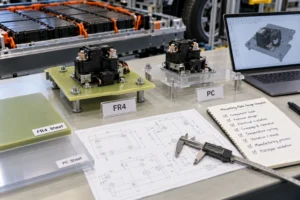
Before freezing a material, document the component type and part number; plate function and installation location; component mass, orientation, connection forces, load duration, vibration and shock; unsupported span, support points and allowable deflection; fastener, washer, insert and bushing geometry; working and relevant transient voltages; solid insulation, creepage, clearance, withstand and insulation-resistance requirements; candidate FR4 and PC grades and thicknesses; temperature, thermal cycles, humidity, condensation and chemical exposure; hole, slot and cutout layouts; flatness and critical tolerances; proposed CNC, die-cut or forming route; edge quality, cleaning, inspection, prototype assembly; and mechanical, electrical and environmental validation criteria.
The checklist is deliberately function-based. A buyer who supplies only “FR4 or PC, same size” has not yet defined the necessary comparison conditions. A design engineer should identify the acceptance criteria that determine whether either material can be released.
RFQ Checklist for Custom EV Battery Mounting Plates
Provide a controlled 2D drawing (PDF, DXF or DWG when appropriate) and a 3D assembly model if available; the component manufacturer/part number; installation location and plate function; component mass, mounting orientation, static and dynamic loads, load duration, unsupported span and allowable deflection; fastener, washer and insert specifications; operating voltage and insulation boundaries; creepage/clearance targets; grade or functional material requirements and candidate thickness; temperature and environmental conditions; perimeter, holes, slots, cutouts, datums, flatness and critical tolerances; expected edge finish and cleanliness; prototype quantity, annual volume, inspection method, and validation expectations.
If material selection is still open, submit application geometry + mechanical requirements + electrical requirements + environmental conditions + manufacturing constraints. That information enables a meaningful comparison of FR4 and PC designs without transferring system-level approval responsibility to the converter.
How Boost Insulation Supports Material and DFM Review
Boost Insulation’s published EV battery module insulation and flame-retardant polycarbonate services cover material and thickness discussions, drawing/DFM review, and precision cutting or CNC-related converting options. These capabilities are relevant when an engineer needs to compare a flat CNC-machined FR4 candidate with a PC sheet or shaped insulating component, or when production features such as holes, slots and inspection datums affect the material decision. The company’s published services do not establish a universal FR4/PC load rating or guarantee approval for a customer’s electrical assembly.
For an engineering review, submit the mounting plate drawing, component layout, loads, voltage and insulation requirements, temperature, fastener details, tolerances, and target quantity. A practical sequence is drawing and requirements → material and DFM review → prototype → customer validation → production release. Final electrical architecture, loads, acceptance criteria and system qualification remain with the responsible design team.
Frequently Asked Questions
1. Is FR4 or PC better for EV battery mounting plates?
Neither material is universally better. FR4 is often evaluated for flat insulating substrates that need board-like rigidity and precisely machined mounting geometry. Appropriate PC grades can be suitable for supported mounts, protective parts, or formed sheet constructions. The decision requires actual component mass, span, allowable movement, sustained load, fastener interfaces, temperature, electrical isolation boundaries, and the finished manufacturing process. Select specific grades and validate representative assembled parts.
2. When should engineers choose FR4 instead of PC?
FR4 may deserve preference when a plate must maintain stable flat geometry while supporting high-voltage components or accurately located hardware, especially where unsupported span and deflection are important. It still needs checks for drilled-hole integrity, bearing stress, laminate orientation, temperature, electrical spacing, and environmental exposure. If a change in support geometry or a suitable PC construction meets the same function, the comparison should include packaging and manufacturability rather than selecting FR4 from stiffness alone.
3. Can polycarbonate support high-voltage battery components?
Yes, an appropriately selected PC grade and mounting-plate geometry can support certain high-voltage battery components when loading, temperature, deflection and fastening requirements are satisfied. This does not make every PC film, molded grade, or flame-retardant sheet suitable for sustained hardware loads. The designer should review long-term deformation, washer pressure, mounting-hole integrity, and thermal behavior, then verify alignment and electrical separation in the installed assembly.
4. How does unsupported span affect FR4 vs PC selection?
A longer span generally increases sensitivity to bending deflection, but the outcome also depends on thickness, width, hole placement, support conditions, applied loads and material grade. A candidate FR4 laminate may offer a useful stiffness advantage in a flat plate, while a supported or suitably shaped PC part may still satisfy the specified movement limit. Compare full component geometries under identical functional loads instead of using a universal span-to-thickness rule.
5. How does long-term creep affect PC and FR4 mounting plates?
Time-dependent deformation can change a mounted component’s position or fastener condition under sustained stress, particularly with elevated temperature. PC grades require careful review of relevant creep and stress-relaxation behavior, but FR4 should not be described as immune to long-term change. Both need a grade-specific assessment and, where required, representative aging or sustained-load tests. The acceptance criterion is retained mechanical and electrical geometry throughout the intended service conditions.
6. Which material handles fastener and washer loads better?
There is no universal answer because the result depends on washer area, preload, hole position, thickness, geometry, material grade and temperature. FR4 needs review for local bearing, drilled-edge cracking and delamination. PC needs review for local deformation, hole damage and long-term relaxation. Either assembly may also have an electrical-spacing problem if the hardware approaches an energized terminal. Test the actual fastened joint rather than comparing only bulk strength values.
7. Can FR4 and PC both provide high-voltage electrical insulation?
Yes, grade-appropriate FR4 and PC can provide solid electrical insulation when incorporated into a correctly designed assembly. Neither eliminates the need to evaluate surface creepage, through-air clearance, conductive fasteners, humidity, contamination, and the relevant working and test voltages. Supplier dielectric-strength figures are screening information under stated conditions, not guaranteed voltage ratings for a custom finished mounting plate. System-level insulation coordination and validation remain necessary.
8. How should engineers validate an FR4 or PC mounting plate?
Confirm material identity, grade and thickness, then inspect the actual part profile, hole locations, critical dimensions, edges and cleanliness. Install the representative electrical hardware and evaluate static and sustained loads, deflection, fastener condition, vibration or shock, thermal exposure and humidity as specified. Measure actual creepage and clearance geometry and complete relevant electrical tests. Review the assembled part after exposure; dimensional acceptance of the loose plate alone is insufficient.
Conclusion: Choose by the Installed Function
FR4 vs PC mounting plates is fundamentally a component-design decision. FR4 can be a useful candidate for rigid, CNC-machined mounting substrates; a suitable PC grade may be preferable for supported or shaped constructions that benefit from toughness and sheet converting. Neither selection follows from one generic datasheet number. Specify the loads, deflection, hardware, electrical geometry, environment and manufacturing route, then verify the assembled design.
Request a technical review: Send your mounting plate drawing, component and load details, electrical insulation requirements, temperature, fasteners, critical tolerances, prototype quantity and annual volume through Boost Insulation’s RFQ channel for a material/DFM discussion and prototype planning. Final qualification should follow customer-defined validation criteria.
Related Posts:
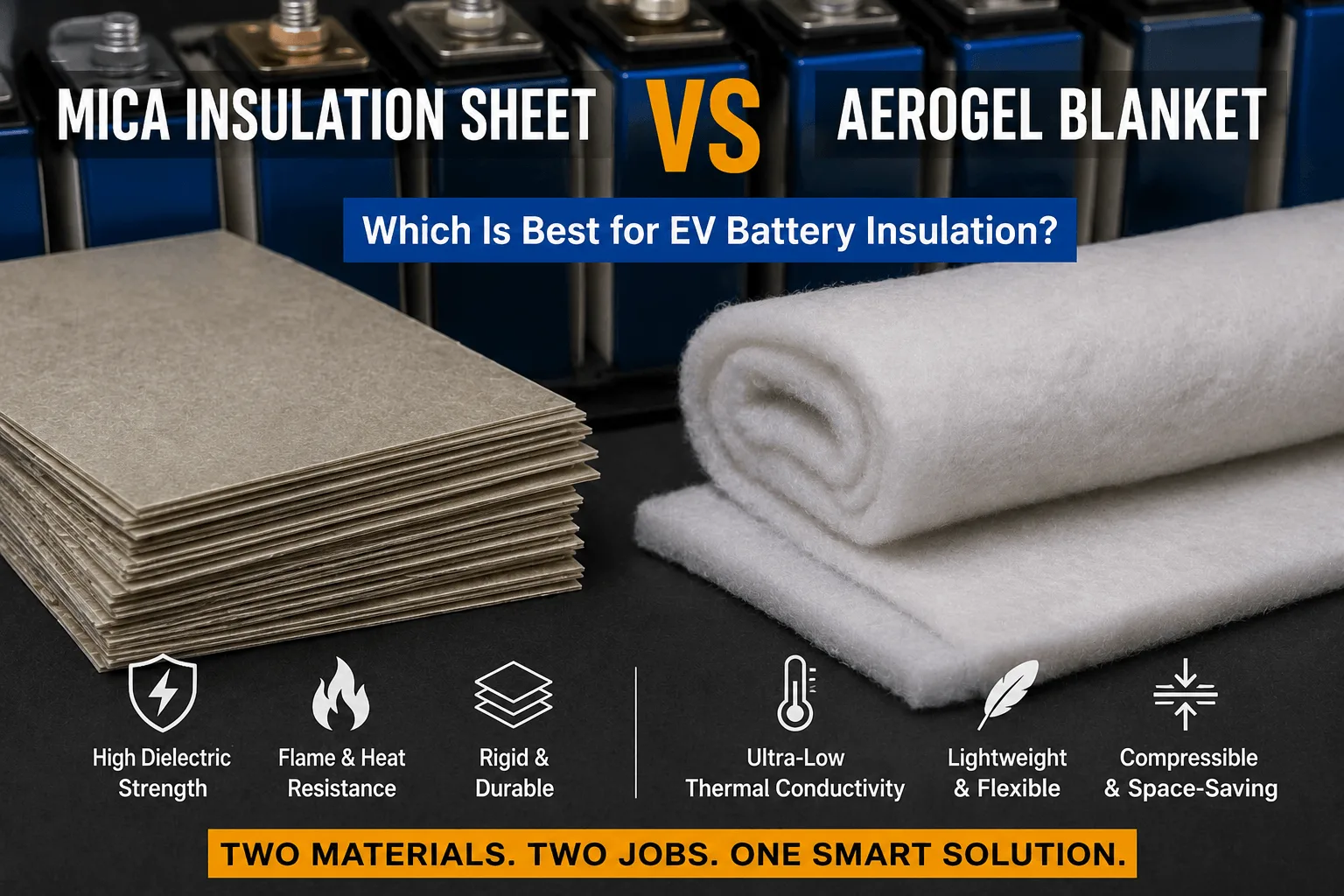
Is a Mica Insulation Sheet Better Than Aerogel for EVs?
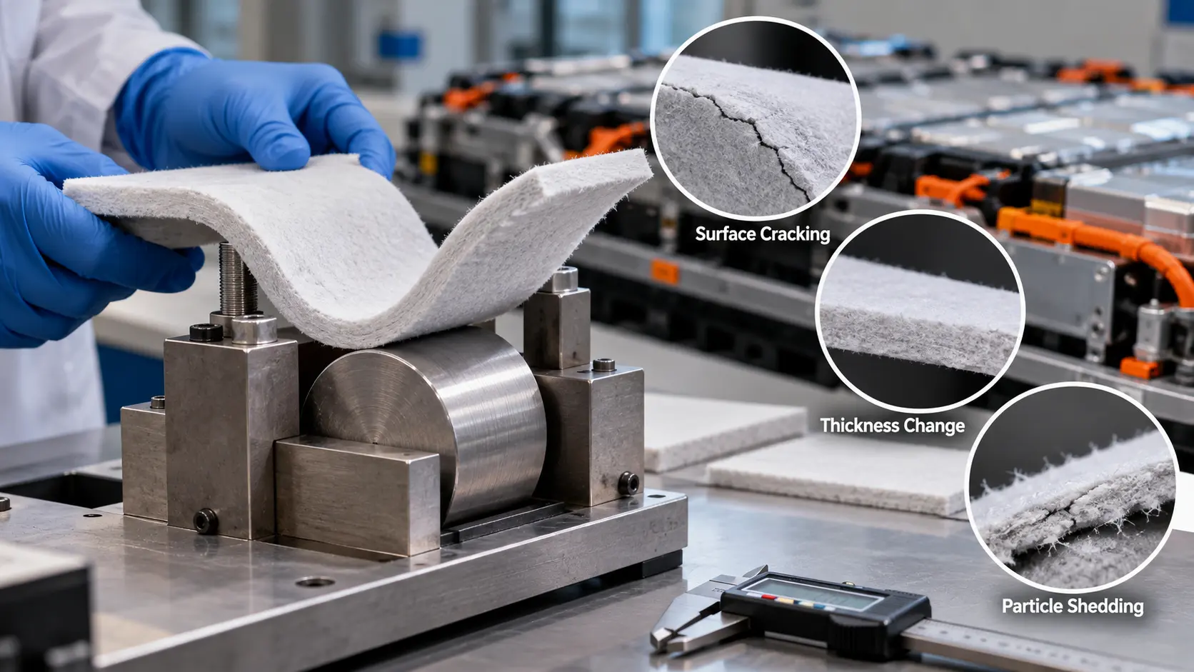
How Do You Test Bend Damage in Ceramic-Fiber Aerogel?
How Do You Select Aerogel Thickness Between Cells?
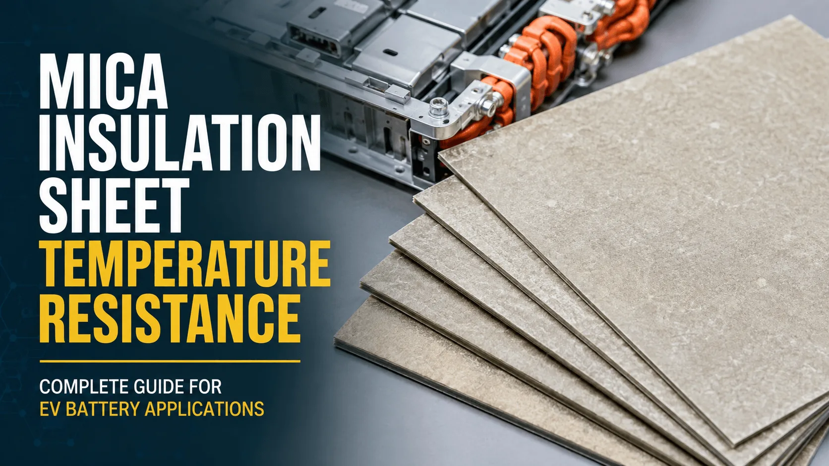
What Temperature Can a Mica Insulation Sheet Withstand?
Which Aerogel Grade Is Best for High-Voltage EV Cells?

How Can Buyers Verify Aerogel Grades for EV Battery Use?
 betty wong
