
Why Use FR4 as Rigid Insulation in EV Battery Packs?
Table of Contents
A thin PET or PI film can electrically isolate a metal surface, and a rigid PC sheet can protect a conductor or electronics area. But what happens when the insulation component must also stay flat across an unsupported span, hold accurate holes and slots, maintain a fixed separation, or support hardware without behaving like a loose film? In those locations, the insulation architecture becomes a mechanical design problem as well as an electrical one. FR4 can fill that gap when a battery pack needs a board-like dielectric component rather than only a thin barrier.
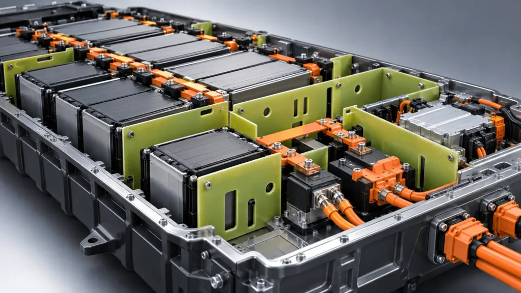
FR4 is used as rigid insulation in EV battery packs when engineers need electrical isolation combined with board-like stiffness, dimensional stability, and mechanical support. Its glass-fiber-reinforced epoxy laminate construction can maintain defined geometry around busbars, terminals, contactors, fuses, module frames, and other conductive structures. Compared with flexible PET or PI films and many polymer sheet constructions, FR4 can occupy a substantially stiffer mechanical role. It is not automatically correct for every location, however: voltage, creepage and clearance, temperature, fire exposure, load, thickness, geometry, machining, mass, environment, and finished-part validation still control the design.
Engineering takeaway
Use FR4 when the insulation component must behave like a rigid board while providing electrical separation. Do not equate rigidity with primary structural load-bearing capability, and do not treat an FR4 flame classification as proof of thermal-runaway barrier performance.
Key Engineering Takeaways
- FR4 is a glass-reinforced epoxy laminate, not simply a hard plastic sheet; the reinforcement changes stiffness, dimensional behavior, machining response, and edge condition.
- Rigid insulation is valuable when geometry must be retained across spans, around mounting hardware, or between energized parts and conductive structures.
- FR4 does not replace creepage, clearance, solid-insulation, fastener, or mechanical-load design. Those requirements must be engineered at system level.
- FR4, rigid PC, PET/PI film, mica, foam, and thermal barriers solve different functions. Hybrid insulation stacks are often more efficient than forcing one material to do every job.
- Thickness alone does not determine rigidity. Unsupported span, cutouts, hole pattern, mounting points, laminate construction, and load direction all influence finished-part deflection.
- For production parts, machining quality, exposed fibers, dust control, cleaning, tolerances, inspection, and final assembly conditions matter alongside the raw laminate datasheet.
What Does Rigid Insulation Mean in an EV Battery Pack?
Rigid insulation is an electrical insulation component designed to retain a defined geometry and limit excessive deformation under its intended assembly and service conditions. In a battery pack, that can mean staying flat between a conductor and a metal frame, preserving the location of mounting holes, bridging an opening, holding a divider shape, or supporting a high-voltage component while maintaining electrical separation.
The important word is intended. A part can be rigid enough to control spacing or support a contactor mounting interface without being qualified as a crash member, compression plate, or primary battery frame. Mechanical support must therefore be tied to a load case: expected force, unsupported span, fastener pattern, vibration, thermal cycling, assembly preload, and allowable deflection. “Rigid” is a functional description, not a blanket structural certification.
Why Do Some EV Battery Insulation Parts Need More Rigidity?
Maintain Defined Electrical Separation
A flexible film can provide an excellent dielectric layer when it is fully supported by the surface beneath it. It becomes less useful when the design depends on the insulation itself to preserve a physical gap or a repeatable boundary. A rigid FR4 divider can help maintain conductor-to-frame, terminal-to-enclosure, or module-to-metal separation because the part retains its geometry after installation.
That does not mean FR4 creates compliant creepage and clearance by itself. Insulation coordination still depends on system voltage, transient stress, pollution conditions, material group, altitude, geometry, and the applicable standard. IEC 60664-1, for example, addresses clearances, creepage distances, and solid insulation for equipment within its scope. The battery designer must apply the relevant vehicle and component requirements rather than substituting a material name for an insulation-coordination calculation.
Reference note: IEC 60664-1:2020+A1:2025
Support High-Voltage Components
Battery junction areas can combine busbars, contactors, fuses, connectors, sensing hardware, and metal mounting structures in a compact volume. In some architectures, a rigid dielectric plate provides a mounting plane or separation panel so that conductive hardware remains located relative to the enclosure. FR4 is attractive here because the same component can provide electrical isolation and a mechanically stable substrate for holes, slots, standoffs, or locating features.
The design still needs to separate “supporting component mounting” from “primary structural load-bearing.” Fastener preload, component mass, vibration, thermal expansion, and fault loads can create stresses that are highly localized around holes and edges. Those loads should be verified on the finished geometry rather than inferred from a generic laminate strength value.
Bridge Unsupported Areas
An unsupported opening exposes a limitation of thin film: the film may insulate electrically, but it may sag, wrinkle, or shift if it has no backing. A rigid board can span that region and maintain a controlled barrier location. This is useful for dividers, insulation plates, junction-area panels, and other components where the electrical boundary must remain in a predictable plane.
Maintain Hole and Fastener Geometry
Battery assembly often depends on repeatable hole alignment. A board-like laminate can keep mounting holes, terminal openings, and locating features registered more consistently than a free film. This can simplify assembly, but the holes also become stress raisers and electrical-geometry features. Hole diameter, clearance, edge distance, washer footprint, preload, nearby cutouts, and conductive fastener paths all belong in the same design review.
Why Is FR4 Suitable for Rigid Battery Insulation?
Electrical Insulation
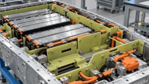
FR4 is a family of glass-fabric-reinforced epoxy laminates widely used in electrical applications. The laminate can provide a solid dielectric barrier, surface creepage path, and electrical separation while also functioning as a rigid component. Exact dielectric strength, insulation resistance, CTI, flammability, and temperature behavior vary by laminate system, conditioning, thickness, supplier, and test method. “FR4” alone is therefore not a complete battery material specification.
Glass-Reinforced Rigidity
The mechanical distinction comes from composite architecture. Woven glass reinforcement carries load within an epoxy matrix, producing board-like stiffness and dimensional behavior that differ from unreinforced thermoplastic films or sheets. The result can be useful where a battery insulation component must resist bending, retain a flat plane, or support precise machined features. It is more accurate to think in terms of a different stiffness class and mechanical function than to describe one insulation material as universally stronger or weaker.
Dimensional Stability
Dimensional stability matters when electrical spacing depends on the location of holes, slots, mounting points, and outer edges. A rigid laminate can help preserve those relationships through handling and assembly. However, laminate construction, machining sequence, humidity, temperature, residual stress, and asymmetric geometry can still affect flatness and dimensions, so critical features should be inspected on the converted part.
Machinability
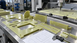
FR4 can be routed, drilled, profiled, slotted, and milled where appropriate. That makes it useful for custom rigid insulation plates that require accurate openings rather than only an external die-cut outline. Machining strategy should be selected around laminate thickness, glass content, feature geometry, edge requirements, tolerances, production volume, dust extraction, and tool wear. A process that is efficient for a prototype may not be the final high-volume process.
Material context: NEMA LI 1 cross-reference | Isola FR-4 laminate example
Where Is FR4 Rigid Insulation Used in EV Battery Packs?
FR4 is most useful where the electrical barrier also needs a stable mechanical form. The exact application varies by pack architecture; the table below maps typical functions without implying that every battery should use FR4 in each location.
| Application | FR4 Function | Why Rigidity Helps | Main Design Concern |
| Busbar divider / barrier | Electrical separation and rigid partition | Keeps the barrier in a defined plane | Creepage/clearance, cutouts, conductor movement |
| HV component mounting panel | Dielectric mounting substrate | Holds holes and hardware locations | Fastener load, component mass, vibration |
| Contactor or fuse insulation support | Separates conductive hardware from structure | Provides stable mounting geometry | Fault current path, heat, local stress |
| Module insulation plate | Separates module or frame interfaces | Resists sagging across broad areas | Unsupported span, thickness, cutouts |
| Terminal barrier | Prevents unintended contact | Maintains barrier shape around terminals | Access openings, edge distance, serviceability |
| Pack-frame insulation panel | Separates HV parts from conductive enclosure | Maintains spacing over larger area | Flatness, mounting, environmental exposure |
| Upper insulation board | Rigid dielectric cover or support layer | Protects and locates upper components | Mass, fastening, vent paths, thermal exposure |
FR4 vs Rigid PC for EV Battery Insulation
Rigid PC and FR4 overlap in some battery insulation locations, but they should not be treated as interchangeable. PC is a thermoplastic sheet that can be effective for tough covers, shields, liners, formed components, and shape-retaining polymer barriers. FR4 is a glass-reinforced thermoset laminate that is often selected when the component needs a more board-like stiffness level, stable machined geometry, or a stronger mechanical-support role.
| Design Requirement | FR4 | Rigid PC |
| Electrical insulation | Suitable with grade-specific verification | Suitable with grade-specific verification |
| Board-like stiffness | Strong use case for rigid panels and supports | Useful for shape-retaining covers; stiffness depends on grade, thickness, span |
| Tough polymer cover | Possible, but often not the most efficient role | Strong use case |
| Mechanical support | Can play a significant supporting role after load validation | Application-dependent; commonly protective rather than board-structural |
| Thin protective shield | Possible, but may add unnecessary rigidity/mass | Often well suited |
| Machined rigid geometry | Strong use case for holes, slots, rigid profiles | Possible depending thickness and process |
| Formed 3D cover | Limited compared with thermoplastic forming | Often more suitable |
| Weight / package efficiency | Application-dependent | Application-dependent |
The design question is therefore not “Which material is better?” It is “What mechanical behavior must the insulation component provide?” A cover that needs impact tolerance and formed tabs may favor PC. A flat mounting plate with accurately located holes and limited deflection may favor FR4. Some assemblies use both.
FR4 vs PET and PI Film
PET and PI are typically selected when the insulation must be thin, flexible, conformal, foldable, or adhesive-backed. They can isolate broad supported surfaces with minimal package thickness. FR4 addresses a different geometry problem: the barrier itself must hold a plane, bridge a span, maintain hole location, or support a mounting interface. Using FR4 where a simple film would work can add unnecessary thickness and machining cost; using film where the barrier must be self-supporting can create assembly instability.
When Is Mica More Appropriate Than FR4?
Mica becomes more relevant when severe heat, flame, hot gas, or post-event dielectric survival dominates the requirement. FR4 is valuable for rigid electrical support within the qualified laminate system, but a flame-retardant designation or UL 94 classification should not be interpreted as battery thermal-runaway certification. If the part directly faces a vent jet or abnormal high-temperature exposure, engineers should evaluate dedicated high-temperature barriers such as mica, ceramic systems, aerogel composites, or other qualified constructions.
This distinction is already important in Boost Insulation’s mica-versus-FR4 guidance: FR4 is positioned around rigid mechanical support and machinable electrical structure, while mica is positioned around high-temperature dielectric and flame-facing functions. The current article therefore keeps the mica comparison narrow and focuses on FR4’s rigid-insulation role.
How Does FR4 Thickness Affect Rigidity?
Thickness strongly affects bending stiffness, but it should not be selected in isolation. Increasing thickness can reduce deflection and improve handling, while also increasing mass, package volume, machining time, and the size of steps or interfaces in the assembly. Example gauges such as 0.5, 0.8, 1.0, 1.5, 2.0, or 3.0 mm can be useful during concept studies, but they are not universal battery recommendations. Availability and performance depend on the exact laminate and supplier.
A more useful selection sequence is: define the span and support points, estimate the mechanical load and allowable deflection, define the electrical requirement, then compare candidate laminate grades and thicknesses. A narrow 1 mm strip and a wide 1 mm plate do not behave the same. Likewise, a 2 mm plate with a large central cutout may be less rigid in the critical direction than a thinner plate with better load paths.
Why Does FR4 Geometry Matter as Much as Thickness?
The finished component, not the sheet coupon, carries the real battery load. Unsupported span, width, length, hole pattern, large windows, narrow bridges, internal corners, edge distance, mounting points, and laminate orientation can all change deflection and local stress. Geometry can also alter creepage surfaces and clearances around conductors. For that reason, FR4 rigidity is a component-design property rather than a single material number.
| Design Factor | Why It Matters | What Engineers Should Check |
| Laminate grade | Controls resin system and qualified properties | Supplier datasheet, construction, approvals, conditioning |
| Thickness | Influences stiffness, space, mass, machining | Candidate gauges, span, load, allowable deflection |
| Unsupported span | Drives bending demand | Support points and worst-case load direction |
| Holes | Remove section and create stress concentration | Diameter, spacing, edge distance, fastener fit |
| Slots / cutouts | Can reduce stiffness and change load path | Window size, narrow bridges, corner radii |
| Fasteners | Introduce local clamp load and conductive paths | Preload, washer, hole clearance, insulation distances |
| Edge distance | Affects local strength and electrical geometry | Hole-to-edge and conductor-to-edge relationships |
| Temperature / humidity | Can change resin response and electrical behavior | Qualified environment and aging plan |
| Tolerance | Controls fit but adds manufacturing cost | Critical vs general dimensions |
| Edge finish / cleanliness | Affects fit, handling and contamination | Chipping, exposed fibers, dust removal, inspection |
How Do Holes Affect FR4 Battery Insulation?
Holes are not neutral features. A mounting hole removes load-carrying section, creates a local stress concentration, and can move the nearest insulating edge closer to a conductor. Fastener holes also interact with screw clearance, washer footprint, assembly tolerance, and clamp load. Terminal and connector openings can create narrow ligaments that are mechanically fragile even when the surrounding plate appears thick enough.
There is no universal minimum hole diameter that applies to all FR4 battery parts. Practical limits depend on laminate construction, thickness, drill or routing process, tool diameter, edge quality, tolerance, production volume, and the remaining material around the feature. The drawing should identify which holes are functional and which dimensions control electrical separation or assembly alignment so the converter can review them appropriately.
How Do Fasteners Affect FR4 Battery Insulation?
A fastener converts a global plate design into a local contact problem. Clamp load enters through the screw head or washer, passes into the laminate around the hole, and then redistributes into the supported structure. Too little bearing area can increase local stress; excessive preload can damage the laminate; large clearance can reduce location accuracy; and a conductive fastener can shorten an intended electrical path if the geometry is not reviewed.
Design review should therefore include fastener preload, washer diameter, hole clearance, edge distance, nearby slots, local crushing or cracking risk, thermal cycling, assembly torque variation, and the relationship between the fastener and energized conductors. Rigid does not mean immune to concentrated load.
How Do Slots and Cutouts Affect FR4 Rigidity?
Slots and windows are often necessary for busbar access, connectors, service tools, harness routing, cooling interfaces, or mass reduction. Each removed region changes the effective section and load path. Large windows can reduce bending stiffness; narrow bridges can become the dominant weak section; sharp internal corners can concentrate stress; and openings can alter electrical spacing. The goal is not to maximize material everywhere, but to preserve the required load path and insulation geometry while removing only what the assembly needs.
Why Do Edge Quality and Machining Matter?
FR4 is reinforced with glass fabric, so machining behaves differently from cutting a homogeneous thermoplastic sheet. Routing and drilling can expose fibers, generate edge chipping, or create roughness if tooling and parameters are poorly matched to the laminate. Those conditions can affect dimensional fit, handling, local mechanical integrity, and cleanliness. Edge acceptance criteria should therefore be tied to the application rather than treated as purely cosmetic.
Machining parameters depend on laminate construction, thickness, tooling, feature geometry, feed strategy, and the required finish. Production drawings should identify critical edges, mating surfaces, or areas near conductors so the supplier knows where edge condition has functional importance.
Why Does FR4 Machining Dust Matter?
Machining glass-epoxy laminate generates particulate debris. In battery manufacturing, the practical engineering issue is process cleanliness: dust can contaminate adhesive surfaces, electrical interfaces, optical inspection, connectors, or assembly fixtures if extraction and cleaning are inadequate. Tool wear can also change edge quality and dimensions over a production run.
A robust process should define dust extraction, equipment cleaning, part cleaning, tool-life controls, packaging, and any contamination-sensitive acceptance criteria required by the battery assembly. These controls are manufacturing requirements, not properties that can be read from a raw-material datasheet.
How Tight Should FR4 Battery Insulation Tolerances Be?
The most efficient drawing does not apply the tightest tolerance to every dimension. Critical dimensions may include fastener holes, terminal openings, busbar clearance boundaries, locating features, mounting points, and edge-to-conductor relationships. A non-functional perimeter or cosmetic outer edge may tolerate more variation. Separating these categories gives the converter room to select an efficient process while protecting the dimensions that control fit or electrical safety.
Unnecessarily tight tolerances can increase CNC time, inspection burden, scrap risk, tool changes, and cost. Conversely, vague tolerances on functional features can create assembly drift. Boost should quote tolerances only after reviewing the exact laminate, thickness, geometry, feature type, and process; this article intentionally does not assign a universal machining tolerance.
How Is Custom FR4 Battery Insulation Manufactured?
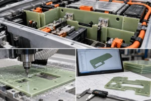
A production-ready FR4 component should move through a controlled sequence: application definition, material specification, drawing review, DFM, process selection, machining, edge and cleanliness review, dimensional inspection, prototype assembly, validation, and then production release. CNC routing and drilling are especially useful for prototypes, changing designs, rigid profiles, holes, and slots. Other cutting or punching processes may be appropriate for specific laminate constructions and volumes, but should be validated rather than assumed.
| Feature | Potential Manufacturing Risk | DFM Question |
| Small holes | Tool wear, chipping, poor repeatability | Is the hole functional, and can its size/tolerance be relaxed? |
| Long narrow slots | Tool deflection, fragile surrounding material | Does the slot need its full length and width? |
| Sharp internal corners | Stress concentration; router radius limitation | Can a practical internal radius be added? |
| Narrow sections | Breakage or distortion during handling | Is enough material left for the load and process? |
| Large cutouts | Reduced stiffness and difficult fixturing | Can support geometry or sequence be improved? |
| Fastener openings | Local stress and alignment sensitivity | Are washer, preload, clearance, and edge distance defined? |
| Critical edges | Chipping or exposed fibers | What edge condition is functionally required? |
| Tight tolerances | Higher cycle time and inspection cost | Which dimensions are truly critical? |
Finished FR4 Part vs Raw FR4 Sheet
A laminate datasheet describes a test material under defined conditions. A battery component adds holes, slots, machined edges, local fastener loads, assembly stress, temperature cycles, humidity, contamination, and aging. Those changes can move the weakest point away from the bulk laminate and into the geometry or interface. That is why raw-laminate dielectric or mechanical data should not be presented as guaranteed finished-part performance.
Validation should use the actual grade, thickness, converted geometry, mounting method, and representative environmental conditioning. Where the design depends on electrical spacing, post-aging insulation, fastener retention, or controlled deflection, those functions should be checked at component or assembly level.
How Does FR4 Compare With Other Battery Insulation Materials?
| Design Requirement | FR4 | Rigid PC | PET / PI | Mica |
| Primary mechanical form | Rigid glass-epoxy board | Rigid/semi-rigid thermoplastic sheet | Thin flexible film | Rigid or flexible high-temperature laminate |
| Electrical isolation | Strong use case; grade-specific | Strong use case; grade-specific | Strong use case in thin supported layers | Strong use case, including high-temperature dielectric roles |
| Board-like support | Strong use case | Moderate/application-dependent | Not a self-supporting board | Construction-dependent |
| Conformal wrapping | Limited | Limited to formed designs | Strong use case | Depends on flexible grade |
| Severe heat / flame-facing barrier | Not automatically a thermal-runaway barrier | Not automatically a thermal-runaway barrier | Usually not the primary severe-heat layer | Strong use case for appropriate mica constructions |
| Machined holes / slots | Strong use case | Possible depending thickness/process | Usually punched/die cut rather than board-machined | Process depends strongly on construction |
| Typical selection question | Do we need rigid electrical support? | Do we need a tough protective polymer cover? | Do we need thin flexible insulation? | Do we need high-temperature dielectric survival? |
Common Mistakes When Designing FR4 Battery Insulation
- Choosing FR4 only from a dielectric-strength number without defining the mechanical role.
- Assuming “rigid” means the part is qualified as a primary load-bearing structure.
- Selecting thickness without considering unsupported span, support points, cutouts, and allowable deflection.
- Ignoring the interaction between holes, washers, fastener preload, and edge distance.
- Creating large cutouts or narrow bridges without checking the resulting load path.
- Applying tight machining tolerances to every dimension instead of identifying critical features.
- Ignoring edge chipping, exposed fibers, machining dust, cleaning, and packaging requirements.
- Treating an FR4 flame classification as equivalent to thermal-runaway flame, hot-gas, or particle resistance.
- Using raw-sheet data as if it were finished-component performance.
- Choosing FR4 where a thin PET/PI film would meet the requirement with less thickness and processing.
- Choosing FR4 where a dedicated high-temperature mica or other thermal barrier is actually required.
Industry Insights for Rigid FR4 Battery Insulation
Controlled geometry matters more as voltage and packaging density increase. Higher system voltage increases the importance of insulation coordination, but it does not create a simple “higher voltage = thicker FR4” rule. Geometry, transients, creepage, clearance, environment, and solid-insulation requirements still need separate evaluation.
Rigid insulation increasingly performs two functions. Battery teams often want one part to provide dielectric separation and a stable mechanical interface. This can reduce loose layers, but it also means electrical and mechanical validation must be connected.
Board geometry can matter as much as nominal thickness. A well-supported thinner plate can outperform a thicker plate with a large unsupported window in the critical deflection direction. Thickness decisions should follow geometry and load definition.
Fasteners often determine the local failure mode. A plate that looks robust globally may crack, crush, or lose electrical spacing around a concentrated mounting point. Washer and preload design deserve early review.
Machining DFM should start before drawing freeze. Hole sizes, internal radii, narrow sections, tolerance strategy, and cleaning requirements are easier to optimize before tooling, fixtures, and inspection plans are locked.
Hybrid insulation architectures are normal. FR4 can provide the rigid board function while PET/PI handles thin local wrapping, PC provides tough covers, foam manages tolerance, and mica or aerogel addresses severe thermal exposure. The system should assign each material a clear job.
Engineering Selection Checklist
Before releasing an FR4 battery insulation design, confirm the following:
- Installation location and neighboring conductive structures
- Electrical function and working voltage
- Applicable creepage, clearance, and solid-insulation requirements
- Mechanical function: barrier, support, mounting panel, spacer, or divider
- Required rigidity, allowable deflection, unsupported span, and support points
- Exact FR4 laminate grade and supplier data
- Candidate thickness and package-space limit
- Normal temperature, thermal cycling, humidity, and environmental exposure
- Any flame-retardancy requirement and its exact test/grade/thickness basis
- Holes, slots, cutouts, narrow bridges, internal corners, and edge distances
- Fastener type, washer geometry, preload/torque strategy, and conductive path
- Critical versus general tolerances
- Machining, edge-finish, dust-extraction, cleaning, and packaging requirements
- Assembly sequence and service/rework access
- Prototype fit, electrical, mechanical, environmental, and aging validation plan
RFQ Checklist for Custom FR4 Battery Insulation
A useful RFQ gives the converter enough context to review the part as a functional component rather than only a 2D profile. Include:
- 2D drawing (PDF plus DXF/DWG where applicable) and 3D CAD if available
- Installation location and the function of the FR4 part
- Specified FR4 grade, or the required performance if the grade is not yet frozen
- Nominal thickness and any thickness constraint
- Working voltage and relevant electrical insulation requirements
- Normal and abnormal temperature conditions
- Flammability or fire-exposure requirement, if applicable
- Overall dimensions, holes, slots, cutouts, and critical edge relationships
- Fastener type, washer size, mounting method, and expected preload if known
- Critical dimensions/tolerances separated from general dimensions
- Edge-finish, cleanliness, labeling, and packaging requirements
- Prototype quantity, annual volume, inspection plan, and validation requirements
RFQ principle
If the laminate grade is not yet selected, provide application conditions and required performance rather than choosing a generic FR4 grade by name. The supplier can then review grade, thickness, geometry, and process together.
How Boost Insulation Supports Custom FR4 Battery Parts
Boost Insulation publicly describes DFM review, CNC processing, die-cutting, material selection, prototyping, lamination, and dimensional manufacturing support for EV battery insulation. For a rigid FR4 project, the relevant starting point is a drawing and application review: define what the board must insulate, what it must support, which dimensions are critical, and whether CNC routing, drilling, or another process is appropriate for the selected laminate and volume.
The engineering workflow should remain drawing-specific. A supplier should not quote a generic “FR4 tolerance” or promise electrical performance without knowing the exact laminate, thickness, feature geometry, edge requirements, mounting method, and validation plan. Prototype parts can then be checked for fit, hole alignment, edge condition, cleanliness, assembly behavior, and the electrical/mechanical functions that matter in the pack.
Useful Boost pages: EV Battery Module Insulation | Mica Insulation Sheet vs FR4 Boards
Frequently Asked Questions
Why is FR4 used as rigid insulation in EV battery packs?
FR4 is used when an insulation part must provide electrical separation while retaining a board-like shape. Glass reinforcement gives the epoxy laminate a stiffness class that can support precise holes, slots, mounting interfaces, and unsupported spans better than a loose flexible film. The finished part still needs load, electrical-spacing, temperature, environment, machining, and assembly validation.
Is FR4 better than PC for battery insulation?
Neither is universally better. FR4 is often useful for rigid mounting plates, dividers, and machined electrical supports. PC is often useful for tough protective covers, shields, liners, and formed polymer components. The choice depends on required stiffness, toughness, geometry, thickness, forming, machining, temperature, flame requirements, mass, and assembly method.
Is FR4 electrically insulating?
Yes, FR4 is a glass-reinforced epoxy electrical laminate family widely used as a dielectric material. However, dielectric strength, insulation resistance, CTI, flammability, temperature behavior, and other properties vary by exact laminate, thickness, supplier, conditioning, and test method. Engineers should specify and validate the actual grade rather than relying on the name FR4 alone.
Is FR4 a structural material in EV battery packs?
FR4 can provide mechanical support, spacing, mounting stability, and shape retention, but “rigid” does not automatically make an FR4 insulation plate a primary structural or crash component. If the part carries significant load, engineers must define the load case, fastener conditions, allowable deflection, environmental exposure, and safety factors and validate the finished geometry accordingly.
How thick should FR4 battery insulation be?
There is no universal thickness. The correct thickness depends on the laminate grade, unsupported span, support points, mechanical load, allowable deflection, electrical requirements, cutouts, fasteners, package space, mass, and manufacturing process. Example gauges can be screened during concept design, but the final selection should be validated on the actual part and assembly.
Can FR4 battery insulation be CNC machined?
Yes. FR4 can be CNC routed, drilled, profiled, and slotted when the laminate and process are appropriate. Because glass reinforcement is abrasive and machining creates particulate debris, tooling, extraction, edge quality, cleaning, inspection, and tool-life controls should be part of the manufacturing plan. Feature limits and tolerances should be reviewed for the exact design.
Is FR4 suitable for thermal runaway protection?
FR4 should not automatically be treated as a dedicated thermal-runaway barrier. Flame-retardant laminate classifications describe defined material tests, not direct resistance to a battery vent jet, hot gas, particles, or prolonged severe heat. Locations dominated by abnormal thermal exposure may require mica, ceramic, aerogel, or another qualified barrier, sometimes combined with FR4 for mechanical support.
When should engineers use mica instead of FR4?
Mica is often more appropriate when the dominant requirement is high-temperature dielectric integrity, flame-facing protection, or survival during severe heat exposure. FR4 is often more appropriate when the dominant requirement is rigid electrical support and machinable geometry. Some battery assemblies use FR4 as the structural dielectric layer and mica as the high-temperature barrier layer.
Conclusion: Use FR4 When the Insulation Must Behave Like a Board
FR4 earns its place in EV battery packs when electrical insulation must do more than cover a surface. A glass-reinforced laminate can maintain a defined plane, support accurate holes and slots, bridge unsupported areas, stabilize high-voltage component mounting, and preserve electrical separation through a rigid geometry. Those advantages are most valuable when the design genuinely needs board-like behavior.
The material still has boundaries. Flexible PET or PI can be more efficient for thin conformal insulation, PC can be more suitable for tough formed covers, and mica or other dedicated barriers can be more appropriate for severe heat and flame-facing exposure. The engineering task is to assign each layer a clear function, then validate the finished FR4 component rather than relying on a generic material label.
Project CTA
If you are developing a custom FR4 insulation part for an EV battery pack, send your drawing, installation location, FR4 grade or performance requirements, thickness, hole and slot geometry, critical tolerances, fastener details, prototype quantity, and annual volume for an engineering and manufacturability review. The practical next step is: Send Drawing → DFM Review → Prototype.
Related Posts:
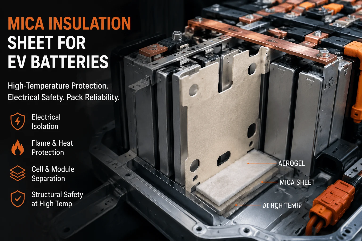
How Does a Mica Insulation Sheet Protect EV Batteries?

How Do You Measure Particle Shedding From Die-Cut Aerogel?
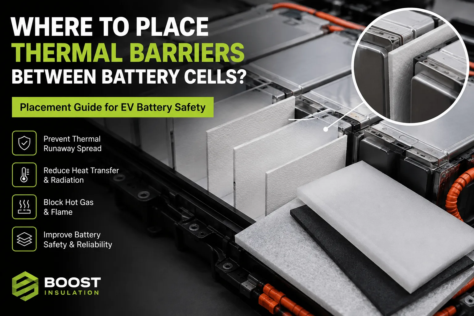
Where Should Thermal Barriers Be Placed Between Cells?
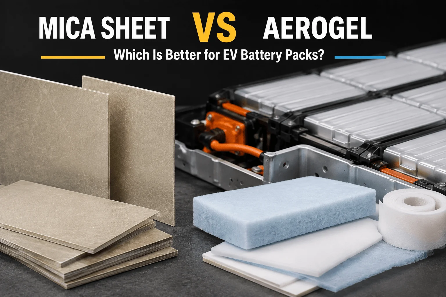
When Should EV Battery Packs Use Mica Instead of Aerogel?
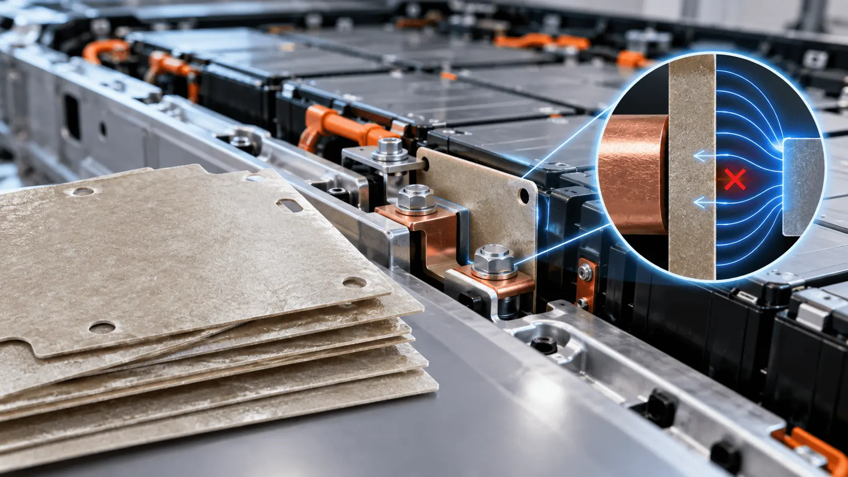
How Does Mica Prevent Dielectric Breakdown in EV Batteries?

How Can You Prevent UV Yellowing in FR Polycarbonate?
 betty wong
