
Can Metal Fasteners Bypass FR4 Battery Insulation?
Table of Contents
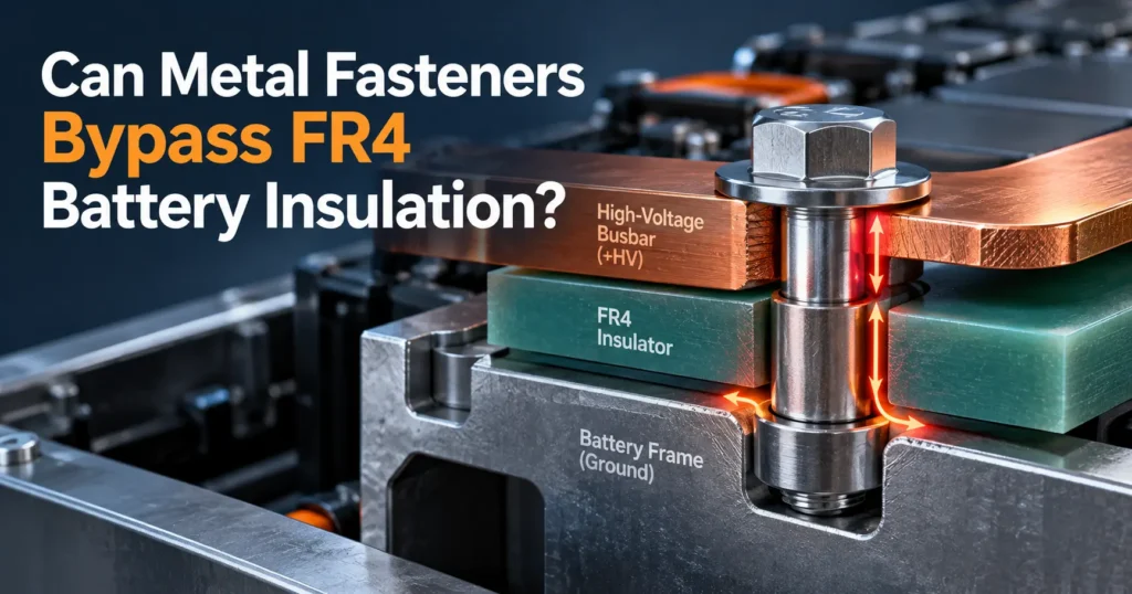
An FR4 plate may separate a high-voltage busbar from a grounded battery frame—until a mounting bolt is installed. The bolt head, threaded shank, metal washer and insert can change the conductive geometry that the original insulation drawing assumed. In some assemblies the hardware forms an unintended metal connection; in others it creates a shorter surface path or moves metal closer to an energized terminal. The critical question is not whether the fastener is metallic, but whether the installed joint preserves the intended electrical isolation.
⚑ QUICK ANSWER
What Counts as a Fastener Bypass—and What Does Not?
A true *direct conductive bypass* is an unintended continuous conductive path around a dielectric barrier. Picture an energized busbar secured to an FR4 mounting plate beside a conductive battery enclosure. If a bolt touches the live busbar and also makes conductive contact with the enclosure, the metal connection defeats the intended separation. The specific contact points, not the presence of FR4 between them, establish the path.
Other conditions can be serious without being direct shorts. A bolt head that approaches the busbar may reduce clearance; a large grounded washer may become the endpoint of a shorter creepage path along FR4. A fastener that remains separated from both sides may be electrically acceptable, subject to insulation-coordination and assembly checks. A chassis-bonding fastener can also be conductive *by design*. The engineering task is to identify intended electrical nodes before judging the joint.
First design rule: label the actual electrical potential of each busbar, enclosure feature, insert, bolt, nut, washer, standoff and component terminal. Treat unknown-potential metal as an open design question, not as automatically grounded or harmless.
Three Electrical Mechanisms Around a Fastener
The three mechanisms need different controls. Do not treat thickness, creepage and clearance as interchangeable substitutes. IEC 60664-1 offers insulation-coordination principles for equipment within its defined scope, including clearance, creepage and solid insulation; the applicable EV-system rules and project requirements must still be established separately.
| Mechanism | Example path | What engineers control | Failure concern |
| Direct conductive bypass | Live terminal → touching bolt → grounded bracket | Contact points, continuity, isolation scheme, assembly hardware | Unintended metal connection |
| Surface creepage | Live conductor → FR4 surface → exposed washer | Surface path, conductive endpoints, contamination, environment | Leakage, surface discharge or tracking |
| Through-air clearance | Busbar edge → air → bolt head | Closest air-gap geometry, transients, tolerances, movement | Air breakdown or arcing |
| Through-material isolation | Busbar → intact FR4 → opposite conductor | Grade, actual thickness, defects, environment and withstand validation | Solid dielectric breakdown |
Direct conductive contact is a circuit question
A CAD section may show a glass-epoxy plate between two metal parts and still conceal a conductive bypass via the hole. Examine the entire conductor chain: under-head face, washer, shank, threads, captured nut, threaded insert and the component contacted on the far side. Insulating the cylindrical shank alone may not isolate the underside of the bolt head. Conversely, a metal bolt in a clearance hole is not a bypass if it makes no unintended connection and the required spacings remain intact.
Creepage is measured along the relevant insulating surface
A metal washer changes the effective conductive endpoint. A large outer diameter may distribute clamp force mechanically while shortening the available surface route toward a busbar. Moisture, ionic residue, dirt and condensing environments influence the assessment. Comparative tracking index (CTI), when relevant, informs material grouping under the applicable framework; it is not itself a creepage distance or a guarantee against tracking. Hole-wall surfaces, grooves and barriers require interpretation under the applicable rules rather than arbitrary added path lengths.
Clearance follows the shortest applicable path through air
A protruding stud, screw tip or washer edge can be closer to energized metal than the nominal mounting bracket. Clearance must be checked using the actual installed three-dimensional envelope and relevant voltage stresses, including transients and altitude where applicable. A dielectric plate does not eliminate the need to evaluate air gaps beyond its boundaries.
How Can a Metal Bolt Form a Direct Conductive Path?
Consider a hypothetical FR4 support between a high-voltage terminal and a grounded metal shelf. If a metal bolt is electrically connected to the terminal at one end and threads into the grounded shelf at the other, current has a metallic route through the joint, irrespective of the FR4 sheet’s published dielectric strength. This is a connectivity problem; simply increasing plate thickness does not interrupt the bolt.
In another arrangement, the bolt threads into a floating insert inside the laminate and does not touch the live conductor or ground. That arrangement may avoid direct bypass, but the insert becomes a conductive object with a potential that must be known or bounded. The design still needs clearance and creepage assessment around the insert, washer and neighboring terminals.
A useful electrical design review traces each fastener as if it were a schematic component. Document what it contacts at assembly, what it might contact under the permitted tolerance extremes, and what connections remain after temperature cycling, vibration or service work. This approach identifies risks that a two-dimensional dielectric drawing can miss.
Do All Metal Fasteners Compromise FR4 Insulation?
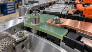
No. A fastener may join equipotential parts, intentionally bond a structure to chassis ground or sit outside any critical insulation boundary. Metal components are routine in high-voltage assemblies; their acceptability depends on system architecture. Insulating an intentional protective-bonding connection could even be an incorrect design change. Never add an insulating shoulder washer before verifying the intended bonding and fault-current strategy.
For an isolated joint, review screw head, washer, shank, nut, standoff and attached structures. The approved electrical architecture must identify allowed metal-to-metal contacts; isolation must survive assembly variation.
How Do Conductive Washers Change Electrical Spacing?
Washers are an especially easy source of missed electrical geometry. Their larger bearing footprint can reduce local compressive pressure in an FR4 laminate, but the outer rim is also exposed conductive metal. Moving that rim toward a busbar can reduce the available insulation distance even if the bolt itself is distant. A washer installed off center may create a different minimum gap than its nominal CAD position.
Define washer type, outside footprint, installed orientation and permitted movement. Include serrated or locking components where they are specified, rather than assuming a flat round disk. If a conductive washer contacts a grounded support but lies near a live conductor, evaluate the washer as the ground-side electrode. A plastic washer placed under a metal bolt head may isolate one surface, while the bolt shank or opposite nut still makes an unwanted connection.
Can Metal Inserts, Bushings and Standoffs Create a Bypass?
Yes, when their electrical connections defeat the intended barrier; no, not simply because these parts are metal. Threaded inserts, captive nuts, compression limiters, sleeves and standoffs can be valuable for mechanical assembly. However, each introduces a conductive surface and may alter where clamp load is carried. A through-metal compression limiter can connect two conductive faces if both ends contact them. A blind insert may remain isolated if its embedded geometry and external clearances are suitable.
Map the electrical connectivity of each insert and confirm whether the screw engages metal on the far side. Review insert retention and potential movement under repeated tightening and environmental cycling. Where conductive inserts are intentionally used, show them as conductive entities in the insulation drawing, not as invisible subfeatures of an FR4 board.
Do Insulating Shoulder Washers and Sleeves Solve the Problem?
They can help isolate selected interfaces, but they do not guarantee a complete insulation system. A shoulder washer uses a nonconductive flange and neck to separate a fastener from a surface and, potentially, from the wall of a mounting hole. Insulating sleeves or bushings can create a radial barrier between a metal shank and surrounding hardware. Manufacturers publish part-specific dimensions and material data; the choice must be matched to the joint. For example, Essentra lists nylon shoulder washers as insulation hardware, but the listed flame classification or catalog dimensions do not establish EV-pack high-voltage suitability.
The flange must cover the intended bearing interface; the sleeve must remain continuous through the critical contact region; and the assembled stack must not crush, extrude, crack or displace the insulator under load. Check the opposite side of the joint. A metal nut or threaded metal standoff can defeat a correctly insulated bolt head if the assembly’s other end reconnects the two electrical nodes. Validate the specific insulating grade against temperature, humidity, mechanical loading and the required electrical tests.
| Fastener arrangement | Potential electrical concern | Mechanical consideration | Design review question |
| Plain through-bolt | Can contact both intended isolation nodes | Simple retention, concentrated bearing interfaces | Which conductive parts touch each end? |
| Bolt and metal washer | Washer changes exposed electrode footprint | Load spreading can benefit laminate | What is the installed washer-to-HV gap? |
| Threaded metal insert | Hidden conductive endpoint or unintended connection | Thread engagement and retention | Is the insert isolated or bonded? |
| Conductive standoff | Could connect structures through height | Controls spacing and mechanical support | Are both ends at compatible potentials? |
| Insulating shoulder washer | Incomplete isolation if neck/flange coverage is insufficient | Polymer compression and seating | Is the entire contact interface protected? |
| Insulating sleeve or bushing | Gaps, damage or incorrect length may expose the shank | Fit, creep and assembly retention | Does protection persist at tolerance limits? |
| Insulated spacer or separated mount | Exposed hardware can still reduce air/surface path | Added stack height and interfaces | What are the actual clearances after assembly? |
What Happens at the FR4 Mounting Hole?
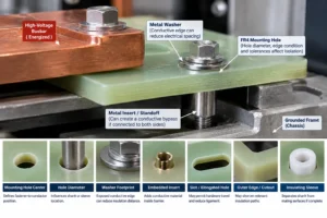
A hole is not electrically neutral. Machining removes local laminate, creates a hole wall and fixes the installed position of the conductive hardware. The design must consider hole diameter, edge condition, center-location tolerance, neighboring energized features, local wall thickness and the remaining FR4 material around slots or cutouts. The hole itself does not automatically become a conductor. Its significance arises from the hardware and electrical geometry it accommodates.
For a bare shank, radial clearance alone is not a full isolation specification. With a sleeve, verify fit and coverage without installation damage. Avoid generic minimum hole, wall or edge distances without grade- and geometry-specific review.
| Feature | Electrical implication | Manufacturing / mechanical implication | Drawing or DFM question |
| Mounting-hole center | Defines fastener-to-conductor position | Drill registration and datum control | Which datum locates the electrical boundary? |
| Hole diameter | Influences shank or sleeve location | Fit, tool selection, edge breakout | What is the allowed installed eccentricity? |
| Metal washer footprint | Moves conductive edge near FR4 surface | Bearing area and washer seating | Is the maximum washer envelope represented? |
| Embedded insert | Adds conductive material inside barrier | Insert seating, retention, damage | Where does the conductive insert terminate? |
| Slot / elongated hole | May permit hardware travel | Assembly adjustment and reduced ligament | What is the worst installed position? |
| Outer edge / cutout | May shorten relevant paths | Routing quality, chipping, cracking | Are critical conductor-to-edge gaps controlled? |
| Insulating sleeve | Separates shank from mating surfaces if complete | Press fit, handling and compression | Can the sleeve migrate or be omitted? |
How Does Tolerance Stack-Up Change the Electrical Risk?
A nominal CAD assembly assumes components are centered and the correct hardware is present. Production assemblies contain variation: hole locations, washer outside dimensions, bolt eccentricity, liner or sleeve fit, plate flatness and the positioning of the busbar or support frame. Evaluate the combined worst relevant installed geometry, not only isolated nominal dimensions. Avoid adding every independent extreme indiscriminately; use an appropriate project-specific worst-case or statistical method with justified assumptions.
Service and rework introduce additional variations. An incorrectly oriented shoulder washer, a missing sleeve or a substituted bolt length can change an otherwise acceptable electrical arrangement. Make high-risk components distinguishable and add inspection points that verify the assembled hardware configuration. Tolerance analysis is an electrical-design deliverable when it affects required creepage and clearance.
| Critical relationship | Potential variation | Consequence | Verification approach |
| Bolt center to busbar | Hole position, bolt eccentricity | Reduced clearance | Assembly-envelope inspection |
| Washer rim to terminal | Washer OD, centering, rotation | New conductive endpoint | Maximum-envelope CAD and physical fit check |
| Sleeve coverage | Length, seat depth, compression | Exposed metal or contact | Section / visual and assembly checks |
| FR4 edge to conductive part | Routing tolerance, part location | Shorter air or surface path | Datum-based dimensional inspection |
| Fastener tip to enclosure | Wrong length, stack height | Unintended contact | Hardware BOM and installation verification |
| Joint movement in service | Vibration, thermal cycling | Spacing drift or insulation damage | Post-environment inspection and electrical tests |
Can Thicker FR4 Stop a Fastener Bypass?
Not if a continuous metal path connects parts that should remain isolated. A thicker board increases the length of the solid insulation path and changes the mechanical stack, but a metal bolt passing through it can still carry an unwanted connection. Thickness also does not automatically deliver adequate creepage or clearance. The design may instead require a different fastener route, an insulating bushing, a relocated mounting point or a redefined bonding scheme.
Select FR4 grade and thickness according to electrical, mechanical, thermal and manufacturing requirements. A raw laminate’s dielectric-strength value, multiplied by its thickness, is not a guaranteed installed withstand rating: test electrodes, specimen condition, edges, voids, humidity and hardware geometry differ. Use a supplier-specific laminate datasheet for material selection and validate the finished joint.
How Do Clamp Load, Vibration and Thermal Cycling Matter?
Fasteners are mechanical connections as well as electrical objects. Torque is an assembly input; achieved clamp load depends on thread and bearing friction, joint materials and other conditions. Excess local bearing pressure can damage an FR4 hole region or a polymer shoulder washer. Damage does not always cause immediate electrical failure, but cracking, shifting hardware and changed surface geometry can undermine long-term insulation margins.
Vibration can produce relative movement or loss of retention in an inadequately designed joint. Differential thermal expansion can alter preload and the positions of metal, FR4 and insulating accessories. An insulation strategy that passes an initial visual inspection should therefore be assessed after relevant mechanical and environmental exposure. Use project-specific test sequences and acceptance criteria.
How Do Contamination and Condensation Interact With Hardware?
A clean FR4 face does not behave identically to a surface carrying coolant residue, ionic contamination, conductive metal particles or condensed moisture. Such conditions can introduce surface leakage or change tracking susceptibility. A metallic washer next to a contaminated surface can create a closer conductive endpoint. Uncontrolled process debris trapped beneath a washer is also an assembly-quality concern.
FR4 machining produces glass/resin debris, which must not all be described as conductive. The more consequential question is whether the part and shared machining or assembly area can also acquire *conductive* particles or residues. Specify suitable cleaning, handling, packaging and incoming inspection according to the actual program. If surface coating is proposed, validate the coating, edge coverage and exposure conditions rather than assuming a coating fixes inadequate spacing.
How Should CNC-Machined FR4 Fastener Parts Be Designed?
DFM review should begin with the electrical drawing. Identify which holes and edges set insulation distances, then tie those features to functional datums. The machinist needs to know whether a location is an electrical-critical dimension or a general perimeter. CNC drilling and routing can create chipped edges, exposed glass fibers or delamination; the acceptable condition must be defined, inspected and validated for the selected laminate and geometry.
Avoid calling every dimension extremely tight. Tight control is most valuable at the bolt-to-busbar, washer-to-terminal, insert-to-conductor and barrier-to-enclosure interfaces. Document suitable hole, slot, edge and profile requirements without inventing universal minima. Keep parts clean after drilling; include the actual insulating sleeve and washer stack in a trial assembly before releasing the design to production.
A workable review sequence is: electrical net identification → hardware stack definition → FR4 grade and geometry → CNC drilling/routing feasibility → prototype assembly → critical-dimension inspection → electrical and environmental checks → release. That sequence reduces the risk of manufacturing a perfectly machined part that cannot preserve the intended high-voltage insulation once installed.
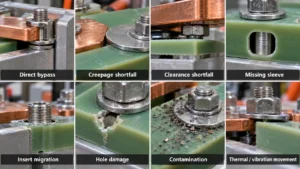
Which Fastener Failure Modes Should Engineers Prioritize?
| Failure mode | Likely initiating condition | Electrical consequence | Corrective review / validation |
| Direct bypass | Bolt touches live and grounded parts | Unwanted conductive connection | Trace nodes; verify contacts and isolation |
| Creepage shortfall | Washer enlarges conductive footprint | Reduced surface insulation margin | Re-evaluate surface path and environment |
| Clearance shortfall | Bolt head or tip approaches HV | Reduced air insulation margin | Check installed 3D envelope and transients |
| Missing sleeve | Assembly omission or wrong hardware | Previously isolated shank becomes exposed | Error-proof BOM and assembly inspection |
| Insert migration | Retention or loading problem | Potential contact or spacing shift | Retention and environmental testing |
| Hole damage | Drilling damage or excessive bearing pressure | Local degradation and changed geometry | Edge/section inspection and load validation |
| Contamination | Particles or process residue | Leakage / tracking risk | Cleaning controls and conditioned testing |
| Thermal/vibration movement | Joint relaxation or differential expansion | Spacing variation over life | Post-cycle retention and electrical assessment |
This screening table does not replace application-specific hazard analysis or qualification.
Common Design Mistakes to Avoid
The following mistakes are frequent sources of incomplete design reviews: (1) assuming any metal bolt automatically shorts the battery; (2) assuming FR4 automatically isolates a through-bolt; (3) omitting fastener potentials from the electrical net map; (4) ignoring under-head contact; (5) treating a metal washer as electrically invisible; (6) overlooking hidden inserts and standoffs; (7) confusing direct continuity with creepage risk; (8) confusing creepage with clearance; (9) relying solely on raw laminate dielectric strength; (10) increasing thickness instead of breaking a conductive path; (11) assuming a shoulder washer cannot be assembled incorrectly; (12) ignoring eccentricity and hole-location tolerances; (13) omitting vibration and thermal cycling; (14) overlooking moisture and conductive debris; and (15) testing only the loose FR4 plate rather than the complete joint.
The corresponding corrective action is not simply “add more insulation.” For each possible path, identify the electrical endpoints, determine how the geometry or interface might fail, define an appropriate mitigation and inspect or test the assembled configuration. Prioritize the failure modes using the customer’s electrical safety analysis and validation requirements.
Six Industry Insights for FR4 Fastener Isolation
- Connectivity comes before material selection. Determine whether the bolt is live, grounded, floating or intentionally bonded before optimizing its surrounding FR4. Otherwise a mechanically attractive mounting choice can contradict the electrical architecture.
- Spacing failures are not short circuits. An exposed bolt may leave the intended nodes disconnected yet reduce creepage or clearance. The mitigation could be repositioning or shielding hardware rather than adding a sleeve to an already isolated shank.
- Washer design carries two functions. A larger washer may reduce localized bearing stress but bring a conductive rim closer to an HV terminal. Mechanical and electrical reviews need a single shared drawing and the same installed hardware envelope.
- An insulating accessory is a component, not a guarantee. Its flange, neck, material grade, compression behavior and orientation must match the fastener stack. A correct catalog part installed backward or at the wrong stack height can defeat its intended function.
- Tolerance control is part of insulation coordination. Electrical separation on a perfectly centered CAD model may not survive production offsets, substitute hardware or movement in service. Inspect the dimensions that actually define the critical paths.
- Qualification belongs to the finished assembly. Raw FR4 tests establish material context, whereas installed-joint tests capture holes, exposed metal, insulating accessories, preload and environmental aging. Both types of evidence have value, but they answer different questions.
Engineering Design Checklist: Electrical Isolation Around Fasteners
Electrical architecture: Record the installation location; functional isolation boundary; relevant working and transient voltages; potentials of busbars, frame, terminals, washers, bolts, nuts and inserts; intentional bonding and grounding; required creepage, clearance, insulation resistance and dielectric-withstand criteria; and applicable standards or customer rules.
Joint geometry: Record FR4 grade and thickness; each fastener type and length; bolt-head, washer and nut envelopes; threaded inserts, standoffs or spacers; insulating sleeves, shoulder washers and their installed orientation; all mounting-hole, slot and cutout dimensions; edge distances; critical datums; and the worst relevant tolerance stack-up.
Service and manufacturing: Record clamp-load or torque requirements from the approved joint design; vibration and thermal cycling; humidity or condensation; contamination sources; hole-edge integrity; cleaning and packaging method; dimensional inspection; assembly verification; electrical validation and post-conditioning inspection. Confirm that any requested isolation accessory does not interrupt an intended protective-bonding path.
RFQ Checklist for a Custom FR4 Fastener Insulation Part
Send the supplier a 2D PDF/DXF/DWG drawing and a 3D assembly if available. Include the busbar and adjacent metal geometry; the actual electrical isolation boundaries and working-voltage requirements; FR4 grade or functional specification; thickness; holes, slots and cutouts; bolt, washer, nut, insert and standoff specifications; any insulating bushings or sleeves; relevant assembly sections; critical dimensions and datum scheme; mechanical load or tightening information; operating environment; surface/edge cleanliness expectations; planned inspection and validation; prototype quantity; and annual volume.
If the isolation concept is still open, provide actual assembly geometry + electrical nodes + fastener details + mechanical requirements rather than requesting only “FR4 with bolt holes.” The supplier can then assess manufacturability and identify geometry questions for the customer’s electrical-design authority before tooling is finalized.
How Boost Insulation Can Support Custom FR4 Interfaces
Boost Insulation publicly describes EV battery insulation material selection, drawing-based DFM review and precision manufacturing support, including CNC-related processing within its battery insulation offering. For a custom FR4 component, a practical discussion would focus on the drawing, laminate specification, hole positions, slots, machined edges, clean handling and prototype fit. See its EV battery module insulation offering and battery insulation material guide for adjacent capabilities.
This is not a claim that Boost independently approves a vehicle’s insulation coordination, supplies a particular fastener accessory or guarantees a voltage rating. Final electrical architecture, hardware selection and battery-system validation remain project-specific. For broader material context, the company’s rigid FR4 battery insulation article and mica-versus-FR4 comparison address different engineering questions without replacing a fastener-specific review.
Conclusion: Validate the Connection, Not Only the FR4
Metal hardware does not inherently defeat FR4 insulation. The risk appears when a joint unintentionally connects different electrical potentials, creates an insufficient surface or air insulation path, or loses the required geometry after manufacture and service exposure. Properly designed insulation accessories and altered fastening layouts may help, but each must be assessed in the complete assembly. A thicker sheet or favorable bulk dielectric datasheet cannot substitute for tracing the actual conductive path.
Engineering RFQ: If you are developing a custom FR4 battery insulation part with bolts, washers or inserts, send Boost Insulation your drawing and fastener assembly details, including the electrical nodes, isolation requirements, busbar/enclosure geometry, bushing details, critical tolerances, prototype quantity and annual volume. The next step is a joint electrical-interface and DFM review followed by customer-controlled prototype validation.
Frequently Asked Questions
1. Can metal fasteners bypass FR4 battery insulation?
Yes, if a metal bolt, washer, threaded insert or spacer unintentionally connects conductors that must be electrically isolated. A fastener can also introduce a new conductive endpoint that reduces creepage or clearance without forming a direct short. Review the real installed contact points and electrical potentials first. The FR4 laminate may remain an effective dielectric while the overall mounting assembly fails to preserve its intended insulation geometry.
2. Does every metal bolt through FR4 create an electrical short circuit?
No. A bolt may be isolated from nearby high-voltage conductors, connect equipotential components or provide intentional grounding. A hole through FR4 does not itself establish electrical continuity between two different potentials. A short-circuit concern arises when the actual metal contact chain bridges an unintended isolation boundary. Engineers must distinguish intentional conductive connections from unwanted contacts and then assess the remaining surface and air insulation distances.
3. Can a metal washer reduce creepage or clearance?
Yes. The washer rim becomes part of the exposed conductive geometry if it is electrically connected to a relevant node. Increasing its outer diameter or moving it closer to a busbar may shorten an air gap or surface path. That same washer may improve bearing-load distribution. Specify and inspect the final washer position and maximum envelope rather than assuming the mechanical benefit makes the electrical layout acceptable.
4. Can metal inserts and standoffs compromise FR4 electrical isolation?
They can when they provide an unintended connection or move metal into a critical insulation path. A metal insert may instead be entirely acceptable when its potential and contact interfaces are properly controlled. Engineers should map both ends of a standoff, threaded engagement and surrounding conductor positions. Review changes caused by preload, movement and manufacturing variation, and validate the installed arrangement rather than rejecting all metal inserts categorically.
5. Do insulating shoulder washers and bushings prevent conductive bypass?
They can interrupt selected metal contact interfaces, provided the insulating material, flange, sleeve length, wall coverage and joint geometry are correctly specified and assembled. They do not independently certify the required creepage, clearance, dielectric withstand, compression behavior or service reliability. A missing sleeve, reversed shoulder washer or metal nut contacting the wrong node may still create an unintended path. Validate the entire fastener stack.
6. Can thicker FR4 stop a conductive fastener from bypassing insulation?
Not when the metal fastener provides a continuous connection between parts that should remain isolated. Increasing laminate thickness does not break a bolt’s electrical continuity. Thickness can affect the through-material insulation path, mechanical support and joint geometry, but creepage and clearance must be assessed separately. A revised fastener route, correctly specified insulating interface or different mounting architecture may be needed instead of simply increasing board thickness.
7. How do vibration and assembly tolerances affect fastener-related insulation?
Hole-position error, bolt eccentricity, washer displacement and incorrect hardware length can reduce the electrical separation available in the installed joint. Vibration or thermal cycling can introduce further movement, changes in retention or damage to an insulating accessory. These effects depend on the actual design and service environment. Critical dimensions should be checked at relevant assembly extremes, with post-conditioning inspection and electrical verification where required.
8. How should engineers validate an FR4 component with metal fasteners?
Begin with an electrical connectivity review of every conductor and fastening component. Inspect critical positions and verify the assembled fastener stack, then apply project-specified insulation resistance, dielectric-withstand and creepage/clearance checks as appropriate. Add mechanical and environmental conditioning that reflects expected service stresses, followed by dimensional and electrical reassessment. Raw FR4 datasheets and tests on loose plates are supporting evidence, not substitutes for installed-assembly validation.
Related Posts:
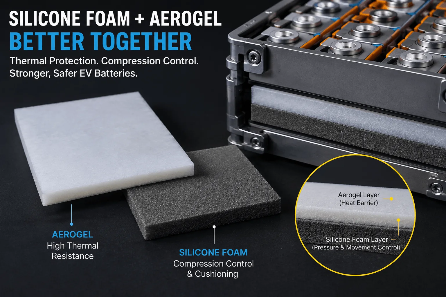
How Does Silicone Foam Work With Aerogel Barriers?
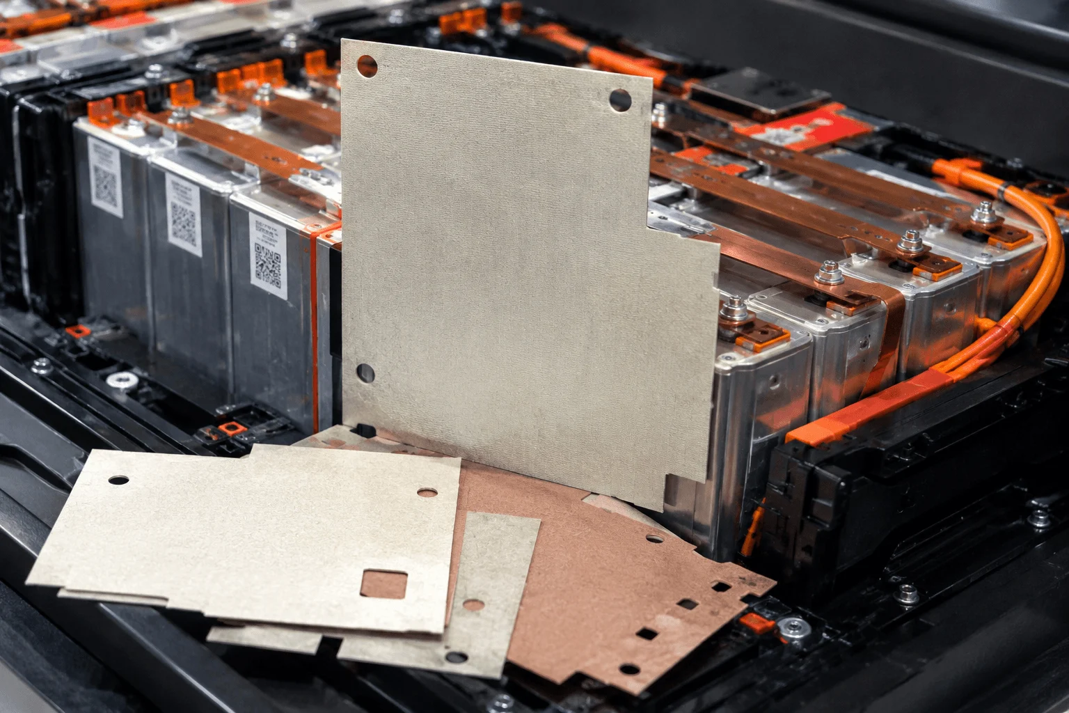
What Is a Mica Insulation Sheet for EV Battery Packs?
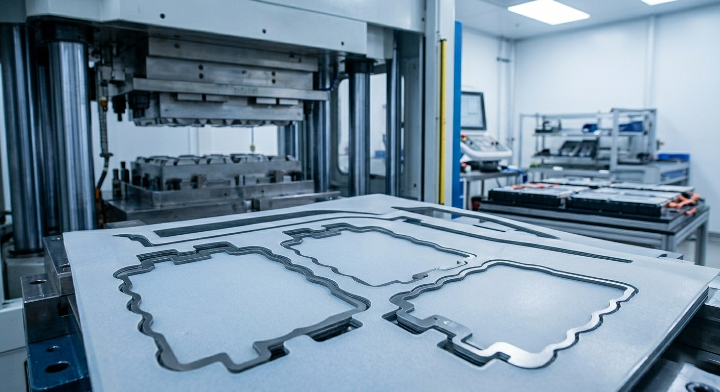
Why EV Battery Modules Need Specialized Insulation?
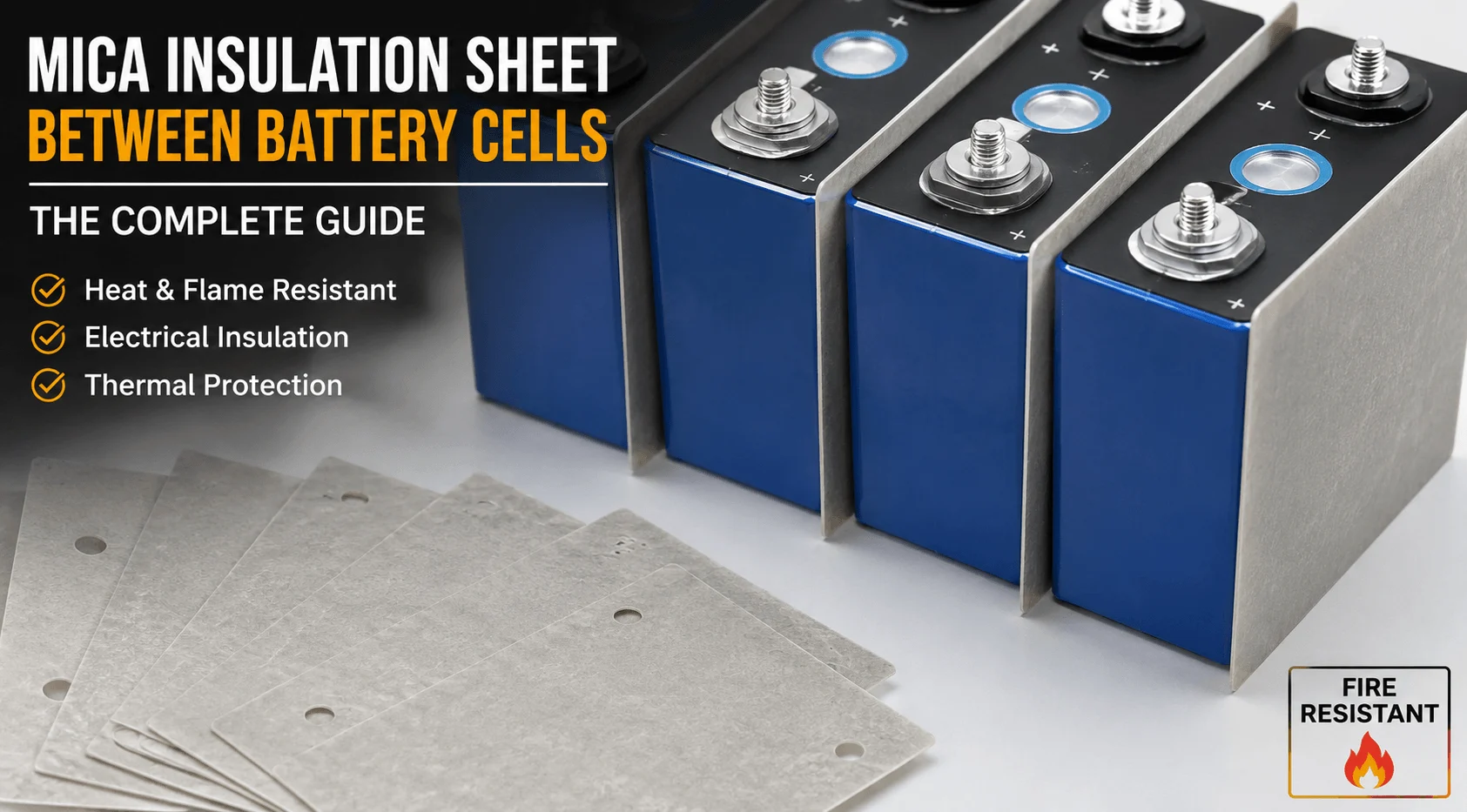
Can a Mica Insulation Sheet Work Between Battery Cells?
Why Does Mica Insulation Survive High Heat in EV Batteries?
How Does FR Polycarbonate Compare to Flame Retardant PVC?
 betty wong
