
How Does Silicone Foam Work With Aerogel Barriers?
Table of Contents
What happens when an EV battery design needs both extremely low heat transfer and a soft material that can absorb tolerances, vibration, and cell expansion? That is where a single insulation sheet often stops being enough. By combining an aerogel thermal barrier with silicone foam in the right locations, engineers can separate the thermal-protection job from the mechanical-management job—and build a battery pack that is easier to assemble, more stable through life, and better prepared for abnormal heat events.
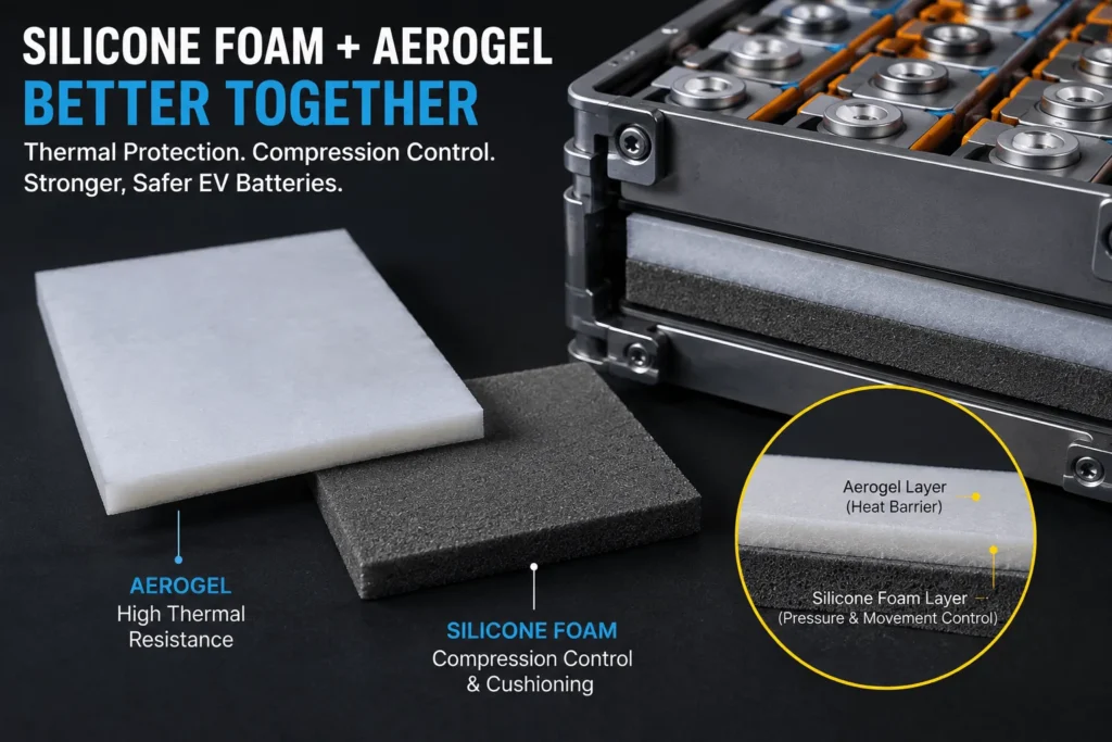
Silicone foam works with aerogel barriers by adding compression control, cushioning, sealing, and tolerance compensation around a highly insulating aerogel layer. In EV battery packs, aerogel primarily limits heat transfer and helps delay thermal propagation, while silicone foam can maintain contact pressure, absorb cell swelling and vibration, close gaps, and protect edges. The best design uses each material only where its function is needed rather than treating them as interchangeable insulation materials.
Why Combine Silicone Foam and Aerogel Instead of Choosing One Material?
The most useful way to compare silicone foam and aerogel is not to ask which material is “better.” They solve different problems. Aerogel is selected when the design is constrained by thermal resistance per millimeter, especially between cells, modules, or other heat-sensitive zones. Silicone foam is selected when the assembly must manage pressure, dimensional variation, vibration, sealing, or repeated compression while still contributing electrical and thermal separation.
This distinction matters because a battery pack is a mechanical system as much as a thermal system. Cell thickness changes with manufacturing tolerance, state of charge, aging, temperature, and electrochemical swelling. Pack covers and module frames move under vibration and thermal cycling. Gaps that look acceptable in CAD can become uneven in production. A rigid or fragile thermal layer placed into that environment without mechanical accommodation can lose contact, fracture, shift, or transfer excessive load into the cells.
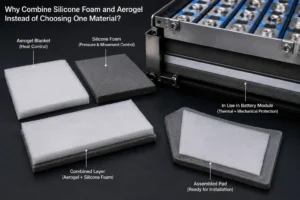
A hybrid design can therefore assign the lowest-conductivity layer to the heat path and the resilient layer to the force path. In simple terms, aerogel controls heat; silicone foam controls movement and pressure. Depending on the architecture, the two can be laminated together, installed as separate adjacent components, or used only in local zones where their functions are needed.
What Does the Aerogel Barrier Contribute?
Aerogel is valued because its nano-porous structure suppresses heat transfer much more effectively than conventional polymer foams at comparable thickness. In battery applications, commercial aerogel pads are engineered as thin thermal barriers that can sit between cells or at module and pack interfaces. Their purpose is not normal battery cooling; it is to resist unwanted heat transfer across a protected direction and, in many designs, to delay or prevent propagation from a cell undergoing thermal runaway to neighboring cells.
A useful current example is Saint-Gobain’s Nor seal TRP720 modified aerogel pad. Its published data lists a typical thermal conductivity of approximately 0.012 W/mK at 50°C for a defined sample construction, and the product is intended for cell-to-cell thermal-runaway mitigation. Aspen Aerogels similarly positions Pyro Thin as an ultrathin thermal barrier for cell-to-cell, module, and pack-level protection. These are product-specific examples, not universal values for every aerogel grade, but they show why aerogel attracts engineers working under severe thickness constraints.
Aerogel can also be engineered to provide some compressibility. That is important: modern aerogel battery products are not necessarily brittle laboratory monoliths. Some commercial pad constructions are designed to accommodate cell thickness changes and provide compression-pad behavior. Still, the mechanical curve of an aerogel barrier may not match the force-deflection, sealing, rebound, or edge-cushioning requirements of the complete assembly. That is the point at which a separate silicone foam can become useful.
What Does Silicone Foam Contribute?
Silicone foam is an elastomeric cellular material. Its engineering value comes from resilience rather than extreme thermal resistance per unit thickness. A properly selected grade can compress to absorb dimensional variation, recover after load, cushion components, isolate vibration, and create a compliant seal over a wide service-temperature range. Many grades also provide useful dielectric properties and flame-retardant options.
Rogers, for example, describes BISCO silicone foams as materials with strong resistance to compression set and mechanical fatigue, with cellular grades used for sealing, cushioning, vibration isolation, heat shielding, and insulation. Published BISCO examples show continuous-use temperature capability up to about 200°C for specific grades, while individual thermal-conductivity values vary by formulation. A firm bun silicone foam example is approximately 0.043 W/mK uncompressed; another cellular grade is around 0.076 W/mK. These figures illustrate why silicone foam can be a good insulator but is usually not chosen to replace aerogel when maximum thermal resistance in minimum thickness is the dominant requirement.
The more important property for many battery engineers is the compression curve. A foam can be tuned by density, firmness, thickness, cell structure, and compression ratio so that it provides a predictable pushback force. This helps maintain pack geometry while accommodating cell growth. When the foam is placed outside the main thermal path, it can perform that mechanical function without unnecessarily increasing the heat flow through the aerogel barrier.
Silicone Foam vs. Aerogel Barrier: The Functional Difference
| Decision Factor | Silicone Foam | Aerogel Barrier |
| Primary engineering role | Compression, cushioning, sealing, tolerance management | High thermal resistance; thermal-propagation barrier |
| Thermal conductivity | Low for a polymer foam, but grade-dependent | Very low; product and temperature dependent |
| Compression behavior | Highly tunable by firmness, density and thickness | Some battery grades are engineered for compression; behavior is product-specific |
| Recovery / compression set | Often a major selection criterion | Not normally the first selection criterion unless the product is dual-function |
| Vibration isolation | Strong use case | Secondary / construction dependent |
| Environmental sealing | Strong use case with suitable cell structure and compression | Normally not the primary role |
| Thermal-runaway protection | Conventional foam: limited; specialized silicone systems can be designed for it | Core use case for battery-grade aerogel barriers |
| Best hybrid position | Perimeter, support zones, gaps, seals, compression locations | Critical heat-transfer path between cells/modules or under protective barriers |
How Can Silicone Foam and Aerogel Be Combined?
There is no single correct stack-up. The best construction depends on where the part sits, what it touches, whether it is compressed, how heat is expected to travel, and what must happen during a thermal-runaway event. Four architectures appear repeatedly in practical design work.
1. Aerogel core with silicone-foam perimeter. In this layout, the aerogel covers the critical heat-transfer area while silicone foam forms a border, frame, or local support zone. This is useful when the center of the part needs maximum thermal resistance but the perimeter must absorb tolerances, protect edges, or maintain a seal. The concept also helps prevent the assembly force from being carried entirely through the aerogel.
2. Aerogel barrier with local silicone-foam islands. Foam pads are placed at selected bosses, ribs, fastener zones, module corners, or controlled contact points. This can stabilize the barrier without putting a higher-conductivity foam layer across the entire thermal path. It is particularly useful when cover flatness or module tolerances create localized gaps.
3. Laminated aerogel-and-foam composite. The layers are bonded into a single converted component to simplify installation. This can reduce part count and assembly mistakes, but it must be engineered carefully. The adhesive coat weight, carrier, overlap geometry, and compressed foam thickness can all change the thermal and mechanical performance. Lamination is a manufacturing convenience only if it does not create a new thermal bridge or undesirable stiffness.
4. Separate functional layers. In many demanding packs, the most robust solution is not to laminate the materials at all. The aerogel sits exactly where heat transfer must be restricted, while silicone foam sits elsewhere as a gasket, compression pad, cushion, or spacer. Keeping the functions physically separate often makes validation easier because the thermal barrier and the mechanical interface can be optimized independently.
Where Does This Combination Make Sense in EV Battery Packs?
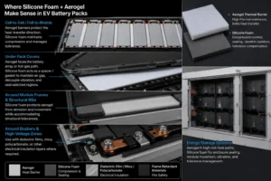
Cell-to-cell and cell-to-module interfaces are obvious candidates, especially in pouch and prismatic architectures where cell swelling creates a real pressure-management problem. Aerogel can protect the sensitive heat-transfer direction, while silicone foam can be used at adjacent structural zones to keep the stack under controlled compression. The important design detail is to avoid creating a foam bypass that carries heat around the aerogel edge.
Under pack covers, the combination can be used differently. A broad aerogel or other high-temperature barrier may face the battery array or a probable hot-gas path, while silicone foam is used as a spacer or gasket to maintain a defined air gap, decouple vibration, or seal selected regions. This is particularly useful when the pack lid is not perfectly flat or when tolerance accumulation could otherwise create point loading on a thin barrier.
Around module frames and structural ribs, silicone foam can protect the aerogel from abrasion and movement. Around busbars or high-voltage zones, the complete stack may also need a dedicated dielectric film, mica, polycarbonate, or other electrical insulation layer. Aerogel and silicone foam should not automatically be assumed to satisfy every dielectric, tracking, or flame-exposure requirement simply because both are described as insulation materials.
In energy storage systems, the same principle applies at larger scale. Aerogel barriers can be placed in high-risk heat-transfer paths, while silicone foam handles enclosure sealing, module movement, vibration, and tolerance variation. The optimal construction is often a system of discrete converted parts rather than one universal sheet covering every surface.
How Does the Hybrid Stack Behave During Thermal Runaway?
During thermal runaway, the thermal event is not a simple steady-state heat-conduction problem. A failing cell can generate intense localized heat, hot gases, flame, particles, pressure, and rapidly changing boundary conditions. The path of those gases can dominate the failure mode. This is why a low thermal-conductivity number alone cannot prove that a stack will protect the pack.
Aerogel is most valuable when it remains in the heat-transfer path long enough to limit the energy reaching the protected side. Silicone foam can help mechanically stabilize surrounding parts, but a conventional foam should not be placed in a direct flame or jet path unless its grade and thickness have been validated for that exact exposure. Specialized silicone-based thermal-propagation materials do exist, and some are designed specifically for severe battery events, but they are different from ordinary gasketing foam.
The design question is therefore not “Will silicone foam survive the same event as aerogel?” It is “What must each layer do before, during, and after the event?” The foam may need to maintain spacing and prevent vibration for ten years of normal service; the aerogel may need to protect an adjacent cell during an abnormal event lasting seconds or minutes. The two materials earn their place in the stack for different reasons.
Compression Engineering: The Part Many Thermal Designs Miss
Compression is one of the strongest reasons to combine materials. Battery cells do not remain dimensionally constant throughout life. Pouch and prismatic cells can swell, and the pack structure must apply enough restraint to maintain electrical and mechanical performance without creating damaging pressure. A foam pad is frequently used to absorb this movement and maintain a useful force window from beginning of life to end of life.
The selection cannot be made from thickness alone. Engineers should evaluate compression-force deflection at relevant strains, stress relaxation, compression set after heat aging, temperature dependence, and the available tolerance stack. A very soft foam may bottom out; a firm foam may over-compress cells or deform a cover. The correct grade is the one whose force curve matches the assembly envelope, not the one with the highest density or the lowest published compression set.
Aerogel products may also have a compression curve, but combining them with a second compliant layer changes the system response. Two compressible materials in series do not behave like either material alone. That means prototype builds should measure actual installed gap, compressed thickness, force, and thermal performance together. If a designer simply adds the nominal thicknesses from two datasheets, the stack can miss the intended contact pressure or exceed the allowed package height.
Do Adhesives Help—or Create a Thermal Bridge?
Pressure-sensitive adhesive is often requested because it simplifies assembly. It can keep a soft foam in position, hold a fragile barrier during module stacking, and reduce operator handling. However, adhesive should be treated as an engineering layer, not as invisible glue.
Acrylic, silicone, and other adhesive chemistries have different temperature limits, dielectric characteristics, peel strength, outgassing behavior, and compatibility with porous materials. A full-surface adhesive layer may also have a higher thermal conductivity than the aerogel it covers. In a thin stack, that can create a parallel heat-transfer path. Edge wraps and overlap seams can be even more important because they may allow heat to bypass the intended barrier.
For this reason, a good DFM review asks whether the adhesive needs to cover the entire surface. Selective strips, perimeter bonding, carrier-free transfer adhesive, mechanical retention, or a protective-film encapsulation may provide enough assembly support with less effect on the thermal design. Adhesive aging under temperature, humidity, electrolyte exposure, and compression should be included in validation.
Sealing, Venting, and Hot-Gas Management
Silicone foam is frequently specified for sealing because it can conform to uneven surfaces and maintain recovery through thermal cycling. That capability is valuable around pack covers, service openings, cooling interfaces, and vent-channel structures. Yet sealing is not always the same as blocking flow. In a battery event, the pack may require an intentionally controlled vent path so that gas does not pressurize the enclosure or attack sensitive zones.
A poorly placed foam gasket can unintentionally redirect hot gas toward an aerogel edge, connector, busbar, or cover joint. Conversely, a properly designed foam seal can help channel gas toward a designated exhaust path. Rogers’ current EV materials guidance explicitly discusses silicone sealing around prismatic-cell vents and exhaust channels as part of hot-gas routing. This is a useful industry reminder: the seal geometry and vent architecture need to be designed together.
When aerogel is installed near a vent path, consider edge protection, particle erosion, encapsulation, and retention after exposure. A thermal barrier that is excellent in flat-plate testing may behave differently if hot gas can reach an exposed edge. System-level testing should reproduce the actual gas direction and mechanical constraints wherever possible.
Electrical Insulation: Do Not Assume Thermal Insulation Is Enough
Battery engineers often use the word “insulation” to mean several different functions: thermal resistance, dielectric isolation, fire resistance, environmental sealing, and even acoustic damping. Silicone foam and aerogel can contribute to electrical separation, depending on formulation and construction, but neither should be selected from a generic family description when creepage, clearance, dielectric breakdown, CTI, or high-voltage isolation is safety-critical.
For 400 V and 800 V architectures, the total stack may need a dedicated dielectric layer such as a flame-retardant polycarbonate film, PET/PEN/PI film, mica, aramid paper, or another qualified electrical insulation material. The thermal barrier can then be optimized for heat and the film for voltage. This functional separation often produces a more defensible design than asking one material to satisfy every requirement.
Converted multi-layer parts can combine these functions, but qualification should be based on the finished construction. Dielectric testing through the final thickness, after environmental aging and compression, is more meaningful than relying only on raw-material data.
Silicone Foam + Aerogel Design Matrix
| Design Requirement | Preferred Starting Point | Hybrid Guidance |
| Need very low heat transfer in minimum thickness | Aerogel first | Add foam only if compression/sealing is also required |
| Need long-term compression and cell swelling control | Silicone foam first | Add aerogel if thermal propagation is a separate risk |
| Need pack-cover spacing and vibration decoupling | Silicone foam | Aerogel may be added on the heat-facing area |
| Need cell-to-cell propagation protection | Battery-grade aerogel or validated thermal-propagation material | Keep foam out of bypass paths unless validated |
| Need environmental seal | Silicone foam | Aerogel normally remains separate from the seal |
| Need a single easy-to-install part | Consider laminated composite | Validate adhesive, compressed stack and thermal bridges |
| Need easiest technical validation | Separate functional layers | Allows independent material optimization and testing |
When Should You Use Silicone Foam With Aerogel Barriers?
Use the combination when the design has two or more independent needs: very low heat transfer plus controlled compression; thermal-runaway protection plus vibration isolation; a thin barrier plus a variable assembly gap; or a high-value thermal layer that needs edge protection and positional stability. The combination is particularly compelling when a single material forces a compromise between thermal performance and mechanical compliance.
Do not automatically use both materials when one can do the job. If the aerogel product already provides the necessary compression behavior and there is no sealing or tolerance problem, adding foam may increase thickness, part count, cost, and validation burden without adding value. Likewise, if the application only needs a moderate-temperature gasket or cushion and there is no severe thermal path, silicone foam alone may be sufficient.
The goal is function density, not material count. Every additional interface introduces possible tolerance, adhesive, aging, and assembly failure modes. A good design adds silicone foam only where it closes a measurable engineering gap.

Industry Insight: EV Thermal Protection Is Moving Toward Functionally Zoned Materials
The direction of EV battery design is increasingly clear: engineers are moving away from the assumption that one large sheet should solve the entire pack. High-energy cells, faster charging, cell-to-pack architectures, larger prismatic formats, and more aggressive packaging all create different local failure modes. As a result, insulation systems are becoming functionally zoned.
One zone may need extremely low thermal conductivity. Another may need a flame-facing barrier. Another needs a soft spring element to accommodate swelling. Another needs a dielectric film around an 800 V busbar. Another needs a gasket that guides vent gas. This favors converted multi-material parts and coordinated material sets rather than a generic “battery insulation pad.”
The regulatory environment reinforces this direction. China’s GB 38031-2025 traction-battery safety standard became effective on July 1, 2026. The standard itself does not tell engineers to use aerogel or silicone foam, but the broader move toward tougher battery-system safety verification increases the value of designs that are validated as complete assemblies rather than selected from individual material ratings alone.
There is also a notable product trend toward dual-function materials. Current aerogel products can provide compression behavior, while specialized silicone systems can provide both pressure management and thermal-propagation delay. That does not make hybrid stacks obsolete; it means engineers now have more architecture choices. The commercial winner will often be the solution that meets the system target with the least thickness, lowest assembly complexity, and most stable end-of-life performance.
DFM Guidelines for Die-Cut Silicone Foam and Aerogel Components
Converting a laboratory material concept into a production part requires attention to details that are easy to miss in early CAD. Aerogel can be dusty or edge-sensitive depending on construction, while silicone foam can stretch, deform, and change dimension under cutting pressure. Tooling, liner selection, adhesive lamination, and part extraction therefore need to be designed around the actual material stack.
Start with the installed condition. Define the nominal gap, minimum and maximum gap, target compression percentage, allowable force, heat-flow direction, and prohibited contact zones. Then decide whether the aerogel and foam should be one component or two. A single laminated part may reduce assembly time, but two separate parts can provide better material utilization and easier independent replacement during prototype iterations.
For die cutting, minimum web widths, hole-to-edge distances, narrow bridges, and sharp internal corners should be reviewed before tooling. Foam can distort around very narrow features. Aerogel constructions may require protective facings or encapsulation to improve handling. Kiss-cut parts on release liners are often easier for operators or automated pick-and-place systems than loose soft parts.
Tolerance specifications should reflect function. A ±0.05 mm outline tolerance may be valuable around terminals or alignment features but unnecessary on a broad thermal area. Thickness tolerance and compressed height can be more important than X-Y geometry for a foam component. Separating critical and noncritical dimensions reduces inspection cost and improves production yield.
What Should Be Validated Before Production?
A high-quality RFQ should include the validation plan, not just the drawing. For the silicone foam, request compression-force deflection at the relevant compression ratios, compression set, stress relaxation, thermal aging, vibration behavior, flammability where applicable, and dielectric data if it serves an electrical function. For the aerogel, focus on thermal conductivity or thermal resistance under the actual compressed state, high-temperature exposure, flame or hot-plate performance, dimensional stability, dust/particle control, and any relevant electrical properties.
For the combined stack, test what the materials do together. Measure compressed stack height, force over time, peel or bond strength, thermal resistance, dielectric withstand, humidity aging, thermal cycling, and part migration under vibration. If the component is intended to mitigate thermal runaway, use application-representative abuse testing rather than assuming that UL 94 or a room-temperature thermal-conductivity value predicts pack behavior.
Also validate the geometry around edges, holes, slots, fasteners, and seams. Thermal events exploit discontinuities. A 2 mm aerogel field with a wide exposed gap around a mounting boss may provide less system protection than a slightly thinner barrier with better edge continuity.
How to Reduce Cost Without Weakening the Thermal Strategy
Aerogel is generally a premium material, so cost optimization should begin with heat-path mapping. Do not cover areas that do not need the lowest-conductivity barrier. Local aerogel islands, strips, or cell-facing zones can sometimes deliver more value than a full-area sheet. Silicone foam can then be used in the mechanical zones without consuming expensive aerogel area.
Nesting efficiency is another major cost driver. Complex die-cut shapes can create high scrap ratios. During DFM, small changes to tab shape, hole placement, part orientation, or panel layout can improve material utilization without changing function. For high-volume programs, the saving from better nesting can exceed the saving from negotiating a lower raw-material price.
Assembly cost matters as well. A pre-laminated multi-layer part may cost more per piece but eliminate separate placement operations, inspection steps, and error-proofing requirements. The correct comparison is therefore total installed cost, including material, tooling, labor, scrap, inventory, rework, and validation—not simply price per square meter.
What Should Buyers Ask a Silicone Foam and Aerogel Converter?
A capable converter should be able to discuss the interaction between materials, not just quote a die-cut drawing. Ask whether the supplier can perform DFM on compression zones and thermal paths, control multi-layer registration, manage liners and adhesives, produce low-dust aerogel components, and provide lot traceability. For automotive programs, ask how APQP, PPAP, change control, measurement systems, and process capability are handled.
Buyers should also ask how prototypes are made. If prototype parts are laser-cut but production parts will be rotary die-cut, the edge quality, thermal exposure, dimensional behavior, and adhesive condition may differ. A supplier should explain which prototype process is production-representative and which properties still need confirmation after hard tooling.
Finally, ask for material data at the thickness and construction you actually intend to use. A UL rating, dielectric value, or thermal conductivity from a different thickness or a different laminate may not transfer directly to the finished part. Good suppliers make this distinction early rather than after qualification testing.
Why Work With Boost Insulation on Aerogel + Foam Constructions?
Boost Insulation positions its aerogel business around material selection, DFM, precision die cutting, multi-layer lamination, rapid prototyping, and automotive-grade production rather than raw sheet supply alone. Its current aerogel page specifically describes integrating aerogel with engineered foam layers and other thermal materials to create multi-layer insulation systems, which matches the engineering logic discussed in this article.
For an EV or energy-storage development team, the practical advantage of working with a converter is the ability to turn several raw materials into one controlled bill of materials and one manufacturable geometry. That can include aerogel barriers, silicone or other foam components, dielectric films, pressure-sensitive adhesives, release liners, and protective facings. The value is highest when the supplier becomes involved before the design is frozen.
Boost Insulation also states that it supports DFM, 48-hour prototyping, cleanroom-controlled converting, in-house testing, APQP/PPAP workflows, and lot traceability. For buyers, those capabilities are relevant because the finished converted part—not the raw material datasheet—is what ultimately enters the battery pack.

RFQ Checklist: What to Send for a Silicone Foam + Aerogel Project
To receive a technically useful quotation, send more than a 2D drawing. Include the application location, battery cell format, nominal and worst-case gap, expected compression, operating temperature range, short-duration abnormal temperature exposure, heat-flow direction, voltage requirement, flame requirement, target lifetime, adhesive preference, annual volume, prototype quantity, and validation standard.
If the part is near a thermal-runaway vent path, provide the vent direction and any available abuse-test data. If the foam controls cell swelling, provide beginning-of-life and end-of-life dimensional ranges or force targets. If the part is under a cover, include cover flatness and fastening conditions. These details allow the converter to recommend a stack rather than merely duplicate the drawing.
A useful RFQ should also state whether the buyer accepts equivalent materials or requires a named grade. This is important for cost-down programs: an equivalent grade should not be substituted solely on density or thickness; the functional parameters must be matched.
Frequently Asked Questions
Is silicone foam a replacement for aerogel?
No. Standard silicone foam is primarily valuable for compression, sealing, cushioning, and durability, while aerogel is selected when very low heat transfer is required in limited thickness. Specialized silicone thermal-propagation materials can cover more functions, but they should be evaluated as specific products rather than as generic silicone foam.
Can silicone foam be laminated directly to aerogel?
Yes, in many constructions, but the aerogel facing, adhesive chemistry, bond area, thermal bridge, compression response, and aging requirements must be evaluated. Sometimes separate parts are a better design than a full-surface laminate.
Which layer should face the battery cell?
It depends on the cell format, event direction, and material construction. If the main goal is cell-to-cell thermal propagation resistance, the aerogel is generally placed directly in the critical thermal path. Foam may sit behind it, around it, or at selected support zones. Thermal-runaway testing should confirm the final orientation.
Does UL 94 V-0 mean silicone foam can stop thermal runaway?
No. UL 94 is a flammability classification under defined small-scale test conditions. Thermal-runaway propagation is a system event involving heat flux, gas, flame, particles, pressure, geometry, and duration. A V-0 rating can be useful, but it is not proof of pack-level thermal-runaway performance.
Can aerogel also act as a compression pad?
Some modern battery-grade aerogel products are intentionally designed to provide compression/tolerance-pad behavior as well as thermal protection. If that mechanical performance meets the pack requirement, a separate silicone foam layer may not be necessary.
What is the best thickness for a silicone foam and aerogel stack?
here is no universal thickness. It should be derived from the thermal-resistance target, available package space, gap tolerance, required compression force, cell swelling, and abuse-test performance. Optimization should use the compressed—not merely nominal—stack thickness.
Is this combination suitable for cylindrical cells?
It can be, particularly for module-level barriers, cover interfaces, cushions, or pack structures. Cell-to-cell designs for cylindrical cells often use different geometries than pouch or prismatic cells, so the placement of foam and aerogel must follow the actual heat and force paths.
What drawings are best for custom die cutting?
DXF/DWG, STEP, or dimensioned PDF files are commonly useful. Include material stack, liner/adhesive requirements, critical tolerances, and an assembly section view so the converter understands how the part is compressed in service.
Conclusion: Use Aerogel for the Heat Path and Silicone Foam for the Mechanical Path
Silicone foam works best with aerogel barriers when the design deliberately separates functions. Aerogel provides the high thermal resistance needed to slow heat transfer or thermal propagation. Silicone foam manages the mechanical realities of the pack: swelling, tolerance, sealing, vibration, contact pressure, and assembly variation. In the right architecture, the combination can produce a more robust component than either material used indiscriminately across the same area.
\The key is to design the interface, not simply stack two insulation sheets. Compression curves, edge geometry, adhesive coverage, vent routing, dielectric requirements, aging, and system-level abuse testing all determine whether the concept works in production.
If you are developing an EV battery, BESS, power-electronics, or other high-temperature insulation assembly, send Boost Insulation your drawing and operating requirements. A DFM review can identify where aerogel is truly needed, where silicone foam adds mechanical value, and whether a laminated or separate-part construction will give you the best balance of safety, thickness, assembly efficiency, and cost.
Project CTA — Get a DFM Review
Send your CAD/PDF drawing, stack height, compression target, temperature exposure, voltage requirement, and annual volume to Boost Insulation. Ask for a manufacturability review of aerogel + foam options, sample construction, and a production quotation.
Technical References Used for Engineering Context
- Boost Insulation — Aerogel Insulation — DFM, engineered aerogel/foam multilayers, precision die cutting, lamination and validation capabilities.
- Boost Insulation — Thermal Management Solution — Thermal foam materials, silicone sheets, insulation sheets and converted thermal-management components.
- Aspen Aerogels — Thermal Runaway Barriers — Battery-grade aerogel thermal barriers and cell/module/pack thermal-propagation applications.
- Saint-Gobain Nor seal TRP720 — Modified Aerogel Pad TDS — Published example of dual-function aerogel compression/thermal barrier properties.
- Rogers BISCO Silicones — Silicone foam compression-set resistance, temperature capability, cushioning and sealing functions.
- Rogers — High Performance Elastomeric Materials for EV Battery Packs — EV pack compression, sealing, venting and thermal-propagation design considerations.
- China National Standard Information — GB 38031-2025 — Official publication and effective date for the current traction-battery safety standard.
Related Posts:
How Do You Design CNC-Machined FR4 Busbar Barriers?
Can a Mica Insulation Sheet Work Between Battery Cells?
How Do You Select Aerogel Thickness Between Cells?
What Properties Make a Mica Insulation Sheet Effective?
How Is Aerogel Used Between Prismatic EV Battery Cells?
How Does PC Insulation Protect EV Battery End Plates?
 betty wong
