
How Is Aerogel Used Near EV Battery Module End Plates?
Your cell-to-cell barriers may be carefully engineered, but what happens when heat reaches the last cell in the stack? The module end plate can become a fast route into aluminum frames, tie rods, side rails, and other conductive hardware. That is why the small insulation zone near the end plate can influence the thermal behavior of the entire module.
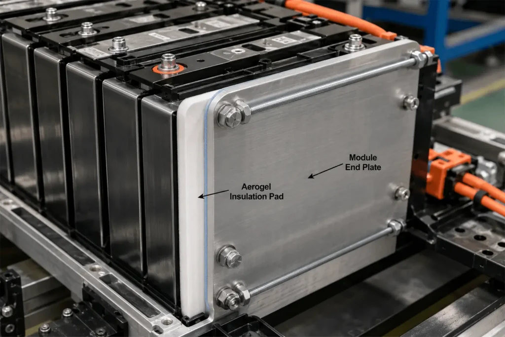
Aerogel near EV battery module end plates is used as a thin thermal barrier between the end cell and conductive end structure, or as part of a layered end-plate pad with mica, polycarbonate, foam, or protective films. Its main job is to reduce heat flow into the end plate, limit structural thermal bypasses, and preserve insulation performance under module compression without blocking vents or intended cooling paths.
For EV battery engineers, the key question is not simply whether aerogel has a low thermal-conductivity value on a datasheet. The useful question is whether the converted part still delivers the required thermal resistance after compression, aging, edge sealing, adhesive lamination, assembly tolerance, and a real thermal-runaway event. End-plate insulation is therefore a system-design problem as much as a material-selection problem.
Aerogel Near EV Battery Module End Plates: Quick Design Guide
| End-Plate Location | Primary Aerogel Function | Critical Design Constraint | Typical Conversion Approach |
| Between end cell and end plate | Reduce through-thickness heat transfer into structural metal | Installed thickness, cell swelling, pressure uniformity | Encapsulated full-face or profiled aerogel pad |
| Between aerogel and rigid dielectric plate | Combine thermal resistance with cleaner electrical/mechanical surface | Layer order, bonding, edge steps, vent clearance | Aerogel + PC or flame-retardant film laminate |
| Behind high-temperature shield | Slow heat after mica protects against flame/ejecta | Hot-side exposure, compression, laminate integrity | Mica + aerogel composite stack |
| Around ribs, rails, or tie-rod regions | Interrupt local heat bridges near structural features | Narrow webs, cutouts, tolerance stack-up | Die-cut strips, islands, or zoned multi-part set |
Why the Module End Plate Is a Hidden Thermal-Propagation Path
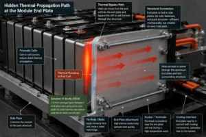
In a conventional prismatic module, cells are stacked between two end plates. The end plates react the preload used to stabilize the stack and control cell swelling. They are frequently tied together by side plates, bands, bolts, or tie rods. Mechanically, that is efficient. Thermally, it can create a bypass around the cell-to-cell barriers.
If an end cell enters thermal runaway, heat can move from the cell can into the end plate and then spread in-plane through the surrounding structure. Aluminum end plates and metallic retention hardware conduct heat far more readily than an aerogel barrier. A strong cell-to-cell design can therefore still underperform if the end interface remains a low-resistance heat path.
This is not only a theoretical concern. A 2024 experimental and simulation study on thermal-runaway suppression added a 1.0 mm aerogel layer between an end plate and a polycarbonate plate specifically to add thermal resistance between the batteries at the module ends and the module end plate. The study describes the intent as blocking heat conduction on the end-plate side. The practical lesson for battery designers is straightforward: map the structural heat paths at the boundaries of the cell stack, not only the interfaces between neighboring cells.
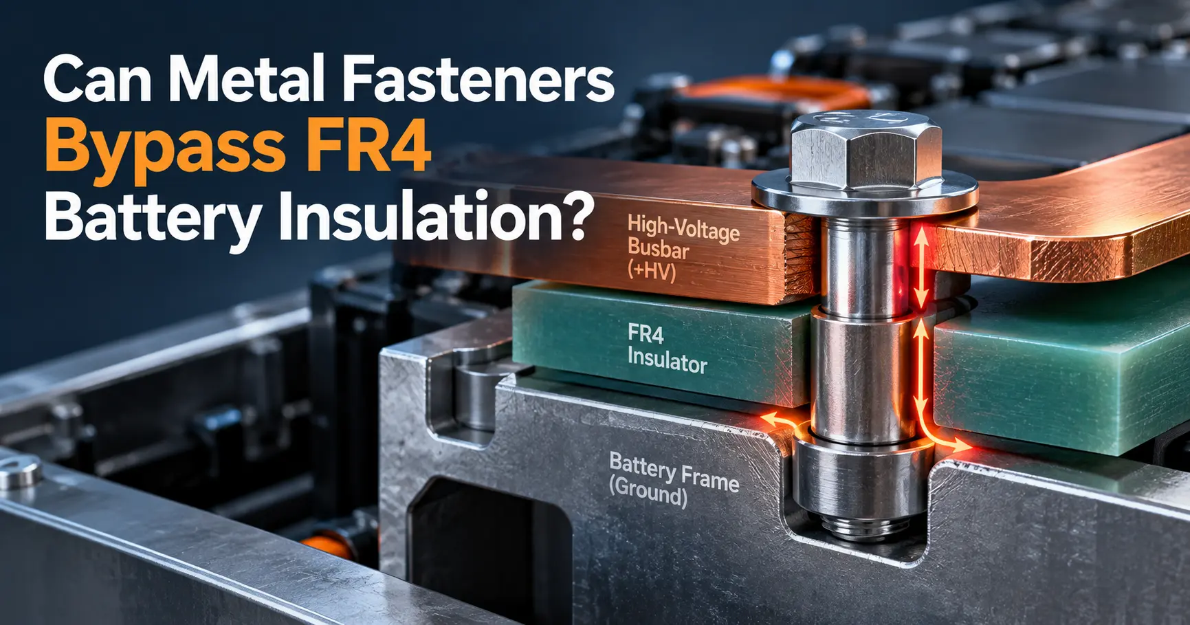
The end plate also connects thermal and electrical risks. It can sit near terminals, busbars, sensing harnesses, cooling components, fasteners, and pack structures. A high-temperature event can therefore turn the end region into a convergence point for conduction, hot gas, conductive ejecta, and electrical isolation challenges. Aerogel helps with the thermal part of that risk map, while other layers may be required for dielectric strength, puncture resistance, flame shielding, or pressure distribution.
Where Is Aerogel Actually Placed Near an EV Battery Module End Plate?
There is no single universal position. The correct placement depends on the cell format, vent direction, cooling architecture, end-plate geometry, allowable gap, and the function assigned to the aerogel. In prismatic modules, four layouts are especially common from a design standpoint.
1. Directly Between the End Cell and the End Plate
The most intuitive layout places a die-cut aerogel pad between the broad face of the last prismatic cell and the inner face of the end plate. This creates a direct thermal break before heat reaches the structural metal. The part may be near-full-face or profiled around shoulders, vents, terminals, cooling contacts, locating features, or retention hardware.
A direct-contact layout is compact, but the aerogel becomes part of the mechanical load stack. The design must therefore define free thickness, installed thickness, compression range, pressure distribution, thickness recovery, and end-of-life cell swelling. An aerogel part that performs well at zero compression can behave differently after years of clamping pressure.
2. Between the End Plate and a Polycarbonate or Other Dielectric Plate
A second architecture places aerogel behind a rigid or semi-rigid dielectric sheet such as flame-retardant polycarbonate. The rigid layer provides a cleaner surface, puncture resistance, dimensional support, and electrical isolation, while the aerogel supplies most of the thermal resistance. This arrangement is attractive when a bare aerogel surface would be difficult to assemble, inspect, or protect from abrasion.
The layer order should follow the real failure scenario. If the end cell is the predicted hot side, the design may place a durable facing layer toward the cell and aerogel behind it. If flame or ejecta can directly impinge on the end structure, a higher-temperature shield such as mica may be more appropriate on the exposed side. The production drawing should define the layer sequence rather than leaving it to the converter.
3. As a Mica-Aerogel End-Plate Stack
Mica and aerogel solve different problems well. Mica provides high-temperature dielectric integrity and physical shielding against flame and hot particles. Aerogel provides much greater thermal resistance per unit thickness than conventional rigid dielectric sheets. A mica-aerogel construction can therefore be useful where the end interface must resist both aggressive hot-side exposure and conductive heat flow into the end plate.
The trade-off is stack complexity. Mica is relatively rigid; aerogel is more compliant and compression-sensitive. Poor lamination can create hard edge steps, local pressure peaks, adhesive squeeze-out, or unprotected seams. The full stack must be tested under the same compression and geometry used in the module.
4. As Local Barrier Strips Around Structural Heat Bridges
Not every end plate needs a single large rectangle. End plates may contain ribs, tie-rod bosses, frame returns, side-rail contacts, or metallic inserts that create concentrated heat paths. In these cases, narrow aerogel strips or profiled islands can be used to increase resistance at the local bridge while leaving required cooling or structural contact areas open.
This layout can reduce material use, but it raises the DFM burden. Narrow webs, small radii, complicated notches, and close hole-to-edge distances are harder to convert consistently. The thermal model should also verify that a local pad does not simply move heat into the unprotected area beside it.
How Aerogel Reduces the End-Plate Thermal Bypass
Aerogel is used because its porous structure can provide very low thermal conductivity in a thin, lightweight layer. At the end plate, that low conductivity increases the through-thickness thermal resistance between the end cell and the structural metal. The result can be a slower end-plate temperature rise and more time before heat spreads into side structures or adjacent regions.
However, the complete thermal network matters more than the nominal material value. Heat can pass through the cell case, contact interfaces, adhesive, aerogel, facing films, end plate, bolts, rails, and cooling components. A single exposed metal contact can run in parallel with the insulation and sharply reduce the benefit of an otherwise excellent aerogel pad.
For preliminary comparisons, engineers often think in terms of thermal resistance increasing with thickness and decreasing with thermal conductivity. In a real EV module, the relevant value is the resistance of the compressed assembly at the temperatures and pressures expected in service and abuse conditions. Contact resistance, compression, temperature-dependent properties, radiation across small gaps, and edge conduction can all change the result.
This is why thermal-runaway validation should instrument more than the center of the end plate. Useful thermocouple locations include the center and corners of the end cell, both faces of the insulation stack, the end-plate surface, tie rods or bolts, side rails, nearby busbars, and the next structural interface. The hottest path is often not the most obvious one on a CAD screenshot.
Aerogel at End Plates Is Different From Aerogel Between Prismatic Cells
Cell-to-cell aerogel and end-plate aerogel are related applications, but they should not be specified as if they were identical. Between two cells, the barrier primarily controls heat transfer from a failed cell to its neighbor while also accommodating cell breathing and swelling. At the end plate, the barrier is adjacent to a stiff structural component that can spread heat rapidly into a much larger metallic network.
The pressure boundary is also different. A cell-to-cell pad sees compression between two moving cell faces. An end-plate pad may see a stiff plate on one side, local ribs or bosses, tolerance accumulation across the complete cell stack, and a different pressure map at beginning of life versus end of life. The same nominal aerogel grade can therefore require a different thickness, reinforcement, encapsulation, or adhesive strategy at the end of the module.
Vent geometry is another distinction. A cell-to-cell barrier normally follows the broad cell face and remains clear of the top vent. At the module boundary, the vent plume can interact with the end plate, terminal hardware, covers, and retention features. Aerogel should not be used to trap a pressure release path. Where direct flame or particle impingement is expected, pair the thermal barrier with a suitably validated shield or deflector.
How Module Compression Changes Aerogel Performance
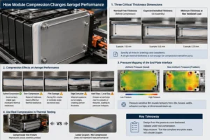
Prismatic cells change thickness during state-of-charge cycling and gradually swell with aging. The module retention system converts that dimensional change into pressure. Because end-plate aerogel can sit directly in this load path, the part must be designed from the pressure curve backward, not selected from free-state thickness alone.
Three dimensions should be separated in the specification: nominal free thickness, expected installed thickness at assembly, and minimum thickness at the maximum validated stack load. A supplier drawing that lists only one nominal thickness leaves too much ambiguity for a compression-sensitive thermal barrier.
Compression can be beneficial when it improves contact and stabilizes the part, but excessive compression can reduce the effective thermal path, change density, damage the facing film, cause edge extrusion, or create a hard step beside a cutout. The exact behavior depends on the aerogel composite construction. This is why supplier stress-strain data should be reviewed together with thermal data rather than as a separate mechanical exercise.
For development programs, pressure mapping is valuable. A thin pressure-sensitive film or appropriate sensor system can reveal whether an end-plate rib, weld, boss, adhesive overlap, or dimensional tolerance is creating a local hotspot in the load stack. Thermal testing should then use a fixture that reproduces the same compression instead of testing a loose coupon.
What Thickness of Aerogel Should Be Used Near the End Plate?
There is no universal aerogel thickness for EV battery module end plates. The required installed thickness depends on the cell energy, chemistry, end-plate material, target cold-side temperature, allowed temperature-rise rate, thermal-runaway duration, available packaging space, compression pressure, swelling allowance, and secondary heat paths.
The 2024 thermal-runaway suppression study mentioned earlier used a 1.0 mm aerogel layer at the end-plate side of its tested design. That is a useful engineering example, not a general specification. A different module with larger cells, a thinner aluminum plate, a different vent direction, higher clamp force, or a more aggressive non-propagation target can require a different construction.
A practical development method is to screen two or three installed-thickness options in the real end-interface stack. Compare cold-side temperature, end-plate heating rate, pressure distribution, total stack growth, part mass, assembly time, die-cut yield, and converted-part cost. The thinnest material that passes the complete validation target with manufacturing margin is usually a better production decision than choosing thickness from thermal conductivity alone.
Why Encapsulation and Edge Sealing Matter for Aerogel End-Plate Parts
Flexible aerogel composites can generate dust or loose particles when cut, rubbed, or repeatedly handled. In a high-voltage battery module, particle control is not a cosmetic issue. Loose debris can contaminate adhesive surfaces, sensing hardware, busbar areas, or automated assembly fixtures. It can also make high-volume handling less predictable.
For this reason, production aerogel parts are often encapsulated or faced with films, scrims, nonwovens, or other protective layers. A perimeter seal can improve cleanliness and handling. The facing can also support printing, barcode labels, orientation marks, or pick-and-place features.
The seal itself must be engineered. A wide perimeter weld or adhesive seam can become a local high-conductivity path or a hard ridge under compression. If the edge seal is thicker than the active aerogel area, the module may clamp on the seal first and leave the center under-compressed. Conversely, an extremely narrow seal may open during die cutting or cycling.
The die-cut drawing should therefore define sealed-edge width, maximum edge step, allowable exposed core, particle criteria, delamination limit, and cut-edge quality. If the part is supplied with a release liner, specify liner split, pull tab, orientation, and whether the liner itself must remain outside critical cleanliness zones.
Should Aerogel Near the End Plate Be Adhesive-Backed?
Pressure-sensitive adhesive can simplify assembly by fixing the aerogel to the end plate or to a carrier before the cell stack is loaded. It is particularly useful when the part must survive subassembly transport, vertical handling, or robotic placement before clamp force is applied.
Full-face adhesive is not automatically the best choice. Adhesive changes thermal contact, adds polymer mass, can soften at temperature, and may create a parallel conduction path. It can also reduce the ability of the aerogel to recover after pressure changes. Selective adhesive zones, registration tabs, perimeter attachment, or mechanical capture may achieve the assembly objective with less impact on the thermal design.
Adhesive qualification should use the real surface finish. Bare aluminum, e-coated steel, painted end plates, polycarbonate carriers, mica facings, and protective films can have very different surface energies. Evaluate peel, shear, creep, high-temperature aging, humidity, electrolyte or coolant exposure where relevant, thermal cycling, liner release, and post-aging repositionability requirements.

How to Combine Aerogel With Mica, Polycarbonate, and Silicone Foam
The most effective end-plate barrier is often a multi-material component rather than a single sheet. The correct stack assigns each layer a clear job and avoids asking one material to solve every failure mode.
Aerogel + Mica
Use this combination when thermal resistance must be paired with a robust high-temperature, dielectric, and flame-facing layer. Mica can protect the surface from direct flame or conductive particles while aerogel slows heat transfer into the plate. Validate the laminate for edge cracking, delamination, pressure concentration, and adhesive behavior at temperature.
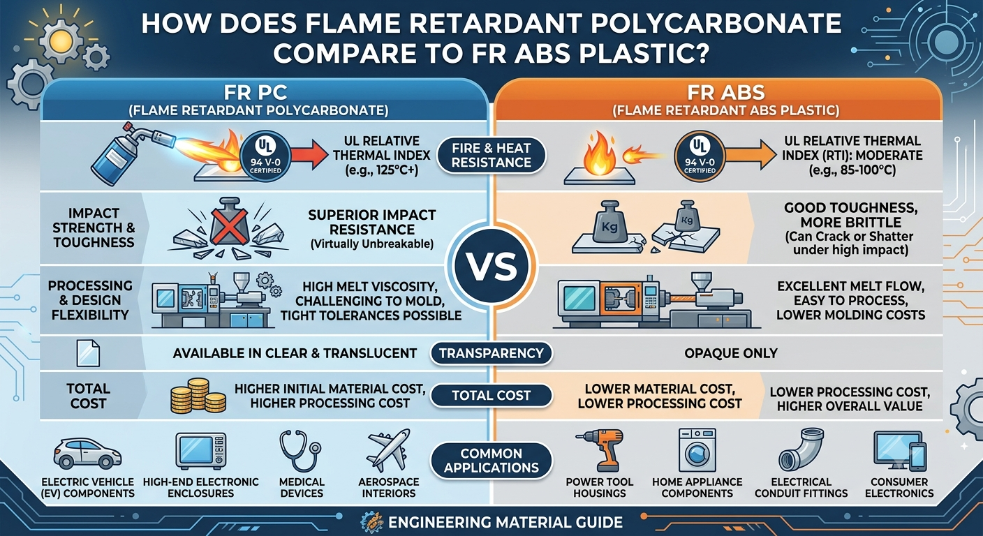
Aerogel + Flame-Retardant Polycarbonate
This combination is useful when the end interface needs a smooth, clean dielectric face, puncture resistance, formed tabs, or locating features. Polycarbonate can make the component easier to handle and assemble, while aerogel provides the thermal barrier. Keep the polymer away from direct severe flame exposure unless the exact construction has been qualified for that condition.
Aerogel + Silicone Foam
Silicone foam can manage larger tolerance and swelling changes that a thin aerogel pad should not be expected to absorb alone. The foam can distribute pressure while the aerogel supplies thermal resistance. The key is to tune the foam compression force so it does not overload the end cell or crush the aerogel below its validated installed thickness.
Aerogel + Protective Film or Scrim
A thin film or scrim can improve cleanliness, handling, tear resistance, and automated assembly. It may also reduce abrasion against the end cell. The facing material and adhesive must be included in the thermal-runaway validation because a low-mass polymer layer can still affect smoke, flame, shrinkage, and edge behavior at high temperature.
DFM Rules for Custom Die-Cut Aerogel End-Plate Insulation
A laboratory aerogel coupon is easy to make. A high-volume end-plate component with repeatable dimensions, clean edges, registered adhesive zones, protective films, vent clearances, and automotive traceability is a different manufacturing problem. Design for manufacturability should begin before the end-plate geometry is frozen.
For custom die-cut aerogel parts, review at least the following features during DFM:
- Minimum web width around terminal windows, vent openings, tie-rod holes, and narrow notches.
- Internal corner radii and sharp re-entrant features that may tear facing films or expose aerogel core.
- Hole-to-edge distances around bolts, studs, locating pins, and structural inserts.
- Perimeter seal width and the tolerance between the sealed zone and the active thermal area.
- Adhesive registration, liner split position, pull-tab direction, and assembly datum strategy.
- Finished thickness and edge-step tolerance after lamination rather than only raw material thickness.
- Part flatness, curl, bow, and stacking behavior for automated feeding or manual assembly.
- Particle-control requirements, clean packaging, interleaf strategy, lot labeling, and traceability.
- Tooling method: flatbed die cutting, rotary die cutting, CNC cutting, kiss cutting, or a hybrid process based on volume and geometry.
- Inspection method for dimensions that are critical to vent, terminal, cooling, and high-voltage clearances.
For high-volume programs, material nesting also matters. A part with many narrow projections or an asymmetric shape can produce high raw-material scrap even when the individual part price looks simple. Early DFM can sometimes move a nonfunctional notch, change a corner radius, or split one large part into two smaller pieces and materially improve yield without changing thermal performance.
How to Validate Aerogel Near EV Battery Module End Plates
Validation should progress from material characterization to the complete module. Skipping the compressed subassembly stage is a common reason a promising coupon result fails when the part reaches a pack test.
Level 1: Material and Laminate
Confirm thickness, areal mass, thermal conductivity or thermal resistance over the relevant temperature range, compression curve, recovery, tensile or tear behavior, high-temperature shrinkage, facing integrity, dielectric properties where applicable, moisture response, and chemical compatibility. For a multi-layer part, test the production laminate rather than assuming raw-layer certificates can be added together.
Level 2: Converted Die-Cut Component
Measure overall dimensions, hole location, edge exposure, seal width, delamination, dust, particles, adhesive registration, liner release, curl, flatness, and finished thickness. The component should be inspected after the real conversion process because cutting pressure, lamination, rewinding, and packaging can alter the part.
Level 3: Compressed End-Plate Subassembly
Build the end cell, aerogel stack, end plate, retention hardware, and adjacent structure at the specified preload. Record installed thickness, pressure map, creep, recovery, and dimensional change through thermal cycling. Include beginning-of-life and end-of-life stack conditions where swelling data are available.
Level 4: Representative Abuse and Thermal Exposure
Apply the relevant heat flux, hot plate, flame, hot gas, particle, or cell-level thermal-runaway trigger. Instrument both sides of the barrier and the structural bypasses. Verify that vents remain functional and that the part does not shift, delaminate, shrink away from the protected region, or create an unexpected ignition path.
Level 5: Module and Pack Validation
The final acceptance criterion must belong to the real battery architecture. Thermal propagation, electrical isolation, venting, warning, enclosure response, cooling interaction, and post-event structural condition are system outcomes. No aerogel datasheet or standalone flammability rating can certify the complete battery pack.
Common Engineering Mistakes With Aerogel at Module End Plates
- Designing excellent cell-to-cell barriers but leaving the last cell in direct contact with a highly conductive end structure.
- Selecting aerogel by free-state thermal conductivity without defining the compressed installed thickness.
- Covering the center of the end cell while leaving a bolt, rail, boss, or plate edge as an uninsulated parallel heat path.
- Using aerogel to block a safety vent or creating a pocket that redirects hot gas toward busbars, sensors, or the neighboring module.
- Expecting one aerogel layer to provide flame shielding, dielectric strength, puncture resistance, and swelling control without complementary materials.
- Adding full-face adhesive late in development without repeating thermal and compression testing.
- Ignoring edge sealing and particle control until the production line is already defined.
- Validating a loose coupon but not the compressed end-plate stack at beginning-of-life and end-of-life pressure.
- Changing aerogel grade, facing film, adhesive, seal method, converter, or thickness after qualification without controlled engineering review.
Industry Insight: Thermal Safety Is Moving From Cell Barriers to Heat-Path Engineering
The battery industry is moving beyond the idea that thermal propagation can be solved by inserting one barrier between adjacent cells. Modern packs are more integrated, more structurally efficient, and increasingly space-constrained. That makes secondary heat paths through cooling plates, busbars, side rails, end plates, fasteners, and pack structures more important.
Aspen Aerogels, for example, explicitly notes that secondary conductive pathways such as cooling plates and busbars must be addressed after cell-to-cell propagation is controlled. The same logic applies to module boundaries: if the end plate remains a low-resistance route around the intercell barriers, the pack is not truly managing the whole thermal network.
Regulatory direction is reinforcing this systems approach. China’s GB 38031-2025 became effective on July 1, 2026. Official interpretations of the revised thermal-diffusion requirement describe a shift from providing a warning before fire or explosion toward requiring the battery pack or system not to catch fire or explode during the specified thermal-propagation test, while still providing an alarm and controlling smoke hazards to occupants. For suppliers, this raises the value of validated components that address not only material flammability but also real heat-transfer paths inside the module.
For sourcing teams, the commercial implication is equally important. The lowest raw-sheet price is rarely the lowest program cost if the part creates high scrap, difficult assembly, dust contamination, unstable compression, or repeated validation loops. The stronger supplier is the one that can translate a thermal requirement into a repeatable converted component: material selection, layer stack, DFM, tooling, clean conversion, dimensional control, traceability, prototype speed, and change management.
How to Specify Aerogel for an EV Battery Module End Plate RFQ
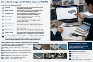
A useful RFQ gives the insulation converter enough context to engineer the part rather than simply quote a rectangle. Include the information below whenever possible.
- Cell format, chemistry, capacity, dimensions, case material, vent location, terminal geometry, and expected swelling.
- Module arrangement, end-plate CAD, end-plate material, surface finish, side-rail or tie-rod structure, and assembly datum scheme.
- Installed gap, target preload, pressure range, beginning-of-life and end-of-life stack thickness, and allowable compression force.
- Cooling method and every surface that must remain thermally coupled to a cold plate or other heat sink.
- Thermal-runaway trigger method, hot-side exposure, cold-side temperature target, required delay or non-propagation acceptance criterion, and sensor locations.
- Electrical requirements if the aerogel assembly also contributes to dielectric isolation, including pack voltage and required test conditions.
- Preferred construction: bare or encapsulated aerogel, aerogel + mica, aerogel + PC, aerogel + foam, adhesive-backed, or open to supplier recommendation.
- Drawing tolerances, edge-seal requirements, particle/cleanliness limits, adhesive zones, release liner design, labeling, packaging, and traceability.
- Prototype quantity, validation stages, annual volume, tooling expectations, PPAP/APQP requirements, target SOP, and change-control requirements.
If the exact aerogel grade or thickness is not yet fixed, state the performance target instead of forcing a premature material callout. A capable insulation converter can often propose two or three stack options that trade thickness, thermal resistance, compression behavior, handling, and cost. That is more useful during development than optimizing only the price per square meter.
How Boost Insulation Supports Custom Aerogel End-Plate Parts
Boost Insulation positions its Dongguan operation as an EV battery insulation and precision die-cutting manufacturer with IATF 16949 and ISO 9001 systems, DFM support, in-house tooling, controlled-environment conversion, rapid prototyping, APQP/PPAP support, and lot traceability. Its published capabilities include aerogel insulation, mica, flame-retardant polycarbonate, silicone materials, thermal materials, films, adhesives, lamination, CNC processing, and precision die cutting.
For a module end-plate project, that manufacturing scope is useful because the final solution may not be a single aerogel sheet. It may require an encapsulated aerogel core, a mica hot-side shield, a PC dielectric carrier, selective PSA, a silicone compression layer, or multiple die-cut pieces that fit around structural features. Converting and inspecting the full stack under one process plan can reduce interface risk between separate material suppliers and converters.
A practical development workflow is to send the end-cell and end-plate CAD, vent and cooling maps, installed gap, compression range, thermal target, and annual volume. The engineering review can then focus on four decisions: where the end-plate thermal bypass is located, how much installed thermal resistance is needed, what layer stack can survive the pressure and abuse exposure, and how to convert that stack repeatedly at production volume.
Planning an EV Battery Module End-Plate Insulation Project?
Send Boost Insulation your end-cell and end-plate drawing, vent direction, cooling interface, installed gap, compression range, thermal-runaway target, and expected annual volume. The engineering team can review custom aerogel, mica-aerogel, PC-aerogel, foam-aerogel, adhesive, encapsulation, and precision die-cut options for prototype and mass production.
Website: boostinsulation.com
Frequently Asked Questions
Why is aerogel placed near EV battery module end plates?
It adds thermal resistance between the end cell and the conductive end structure. This can reduce heat flow into the end plate and limit a structural thermal bypass around the cell-to-cell barriers.
Is aerogel placed directly against the end cell?
It can be, but not always. Aerogel may sit directly between the end cell and end plate, behind a polycarbonate dielectric plate, behind a mica shield, or in a multi-layer compression pad. The correct position depends on pressure, venting, electrical isolation, and flame exposure.
Can aerogel replace mica at a battery module end plate?
Not automatically. Aerogel is primarily valuable for thermal resistance, while mica is often selected for high-temperature dielectric integrity, flame shielding, and particle protection. Many demanding designs use the two materials together.
How thick should end-plate aerogel be?
There is no universal thickness. Specify the required installed thermal performance under the real compression load, then validate candidate thicknesses in the complete end-interface stack.
Does compression reduce aerogel performance?
Compression changes thickness, density, contact conditions, and mechanical behavior. The effect depends on the aerogel composite. Use thermal and stress-strain data at the intended installed pressure and verify the finished part in a compressed fixture.
Should aerogel cover the whole end cell?
Near-full-face coverage is a common starting point for a flat prismatic end cell, but the profile must preserve safety vents, intended cooling contacts, terminal clearances, and structural features. Local barrier strips may be better around some heat bridges.
Why encapsulate a die-cut aerogel part?
Encapsulation improves cleanliness, handling, abrasion resistance, and assembly consistency. The edge seal and facing layers must still be designed so they do not create hard pressure ridges or unwanted thermal bridges.
What information should I send for a custom aerogel end-plate quote?
Send the cell and end-plate CAD, vent and cooling locations, installed gap, compression range, thermal target, electrical requirements, preferred laminate construction, prototype quantity, annual volume, and PPAP or traceability needs.
Technical References and Engineering Sources
- Boost Insulation – Aerogel Insulation. Published capabilities for aerogel conversion, DFM, lamination, prototyping, testing, and high-volume production. Source
- Boost Insulation – EV Battery Module Insulation. Published EV battery insulation, aerogel, mica, PC, lamination, tooling, and automotive production capabilities. Source
- Ye, Z. & Fu, X. (2024), Scientific Reports – Experimental and simulation investigation on suppressing thermal runaway in battery pack. Reports an added 1.0 mm aerogel layer at the module end-plate side to increase thermal resistance and block heat conduction through that path. Source
- Aspen Aerogels – Do Not Just Delay Cell-to-Cell Thermal Propagation, Stop It. Discusses compressed aerogel thermal barriers, prismatic-cell testing, and secondary conductive heat pathways in battery packs. Source
- China National Standard GB 38031-2025 – Electric vehicles traction battery safety requirements. Mandatory Chinese traction-battery safety standard, issued March 28, 2025 and effective July 1, 2026. Source
- UN Regulation No. 100, Revision 3. UNECE requirements for electric power train and rechargeable electrical energy storage system safety. Source
Related Posts:
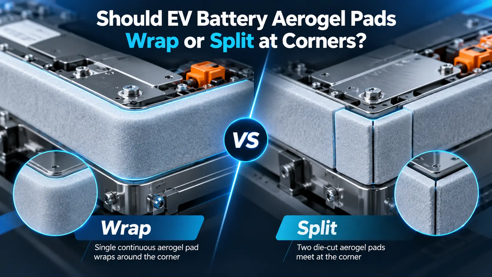
Should EV Battery Aerogel Pads Wrap or Split at Corners?
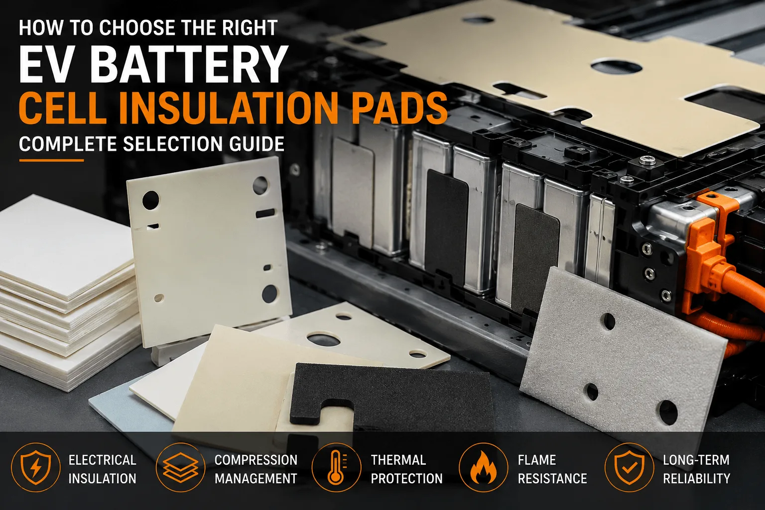
How to Choose EV Battery Cell Insulation Pads?
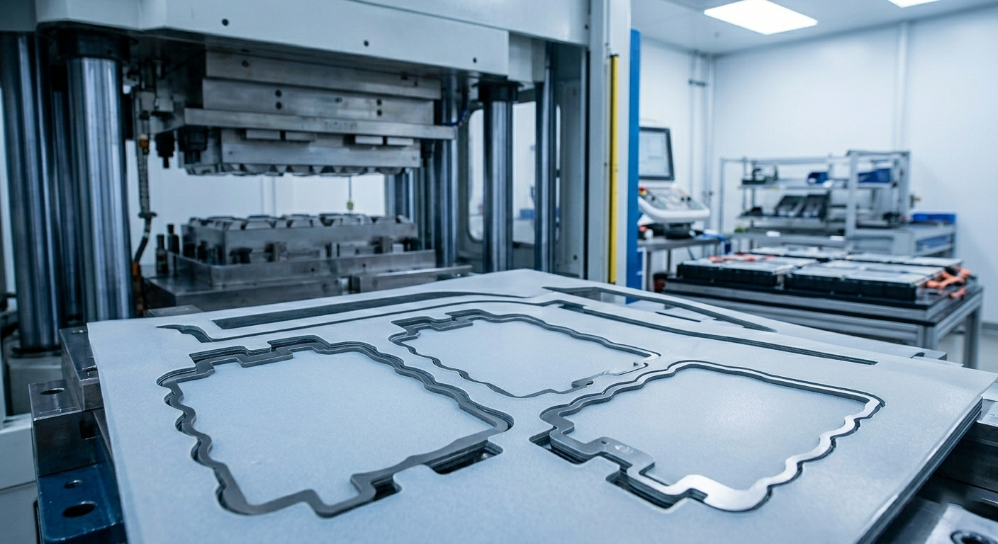
Why EV Battery Modules Need Specialized Insulation?
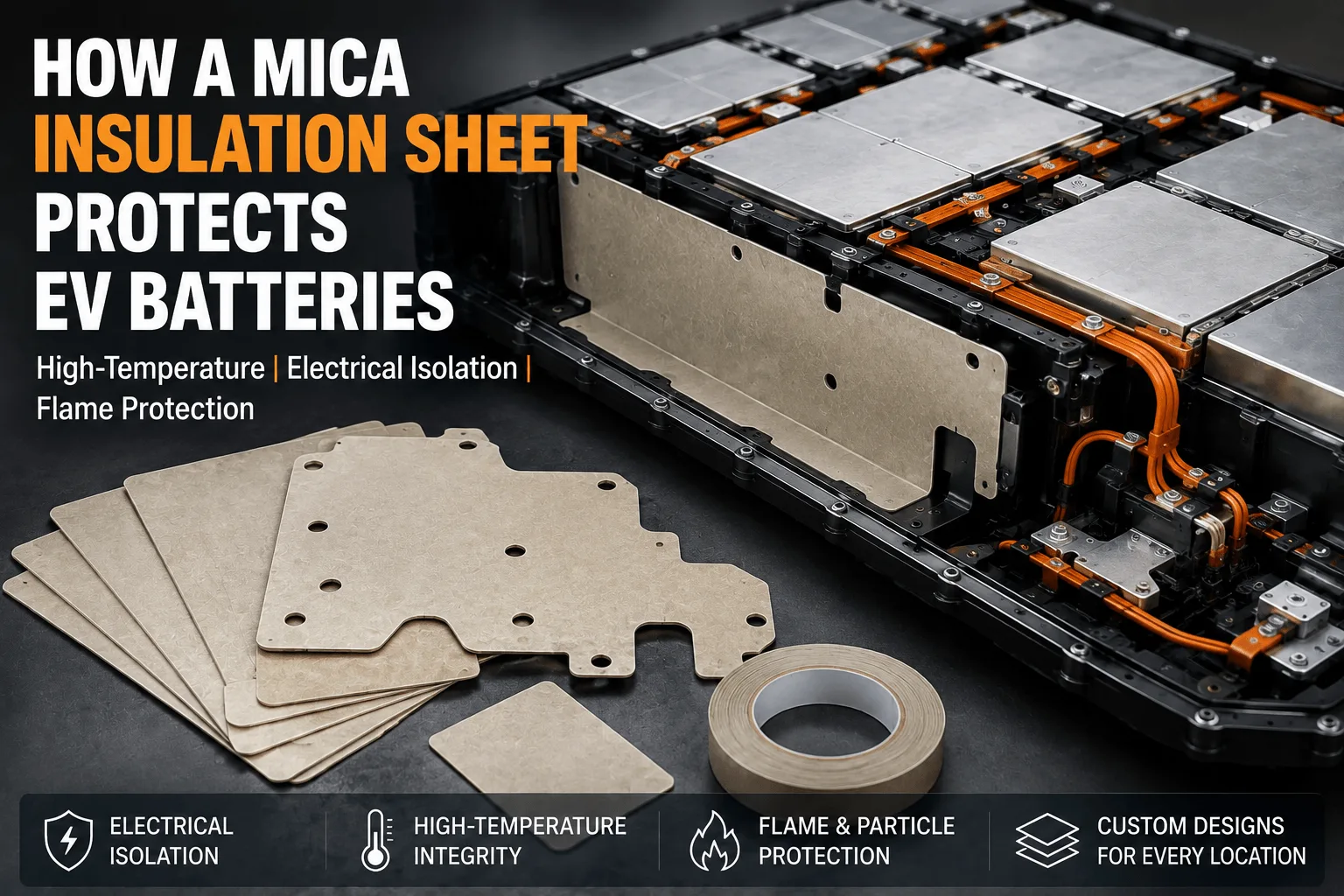
Why Do EV Battery Packs Use a Mica Insulation Sheet?
How Does Flame Retardant Polycarbonate Compare to FR ABS Plastic?
Can Metal Fasteners Bypass FR4 Battery Insulation?
 betty wong
