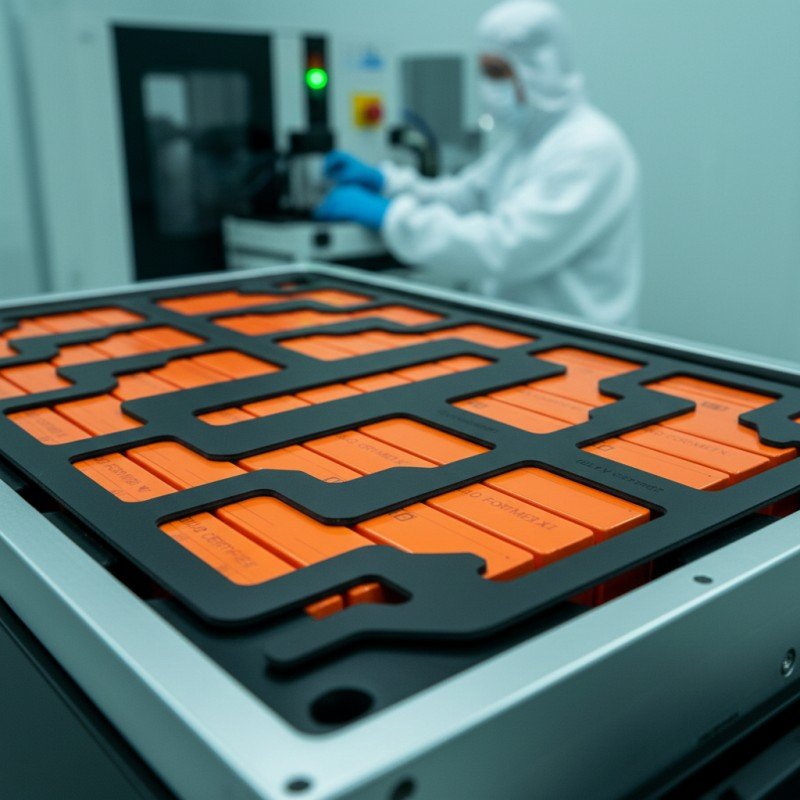
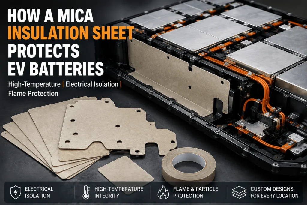
Why Do EV Battery Packs Use a Mica Insulation Sheet?
Table of Contents
Why would an EV battery pack add a thin mica component when it already contains cooling plates, polymer films, thermal pads, sensors, and a metal enclosure? Because those systems do not all remain effective during the same failure. When a cell vents flame, a busbar shifts toward grounded metal, or a pack-cover polymer begins to soften, the design needs an insulation layer that can remain electrically nonconductive and physically present under extreme heat.
| EV battery packs use a mica insulation sheet because it combines high-temperature structural integrity, electrical insulation, flame resistance, and flexible part design. Mica sheets protect busbars and high-voltage components, shield pack lids and module walls from hot gas, flame, and particles, and help limit thermal-runaway propagation between cells or modules. They do not replace cooling, aerogel, silicone foam, vent routing, or pack testing; they provide one durable barrier within a validated battery-safety system. |
Why EV Battery Packs Use Mica: Quick Decision Matrix
| EV Pack Need | Why Mica Is Used | Typical Location | Required Validation |
| High-voltage isolation | Dielectric barrier that retains integrity under heat | Busbars, junctions, frames | Withstand voltage, aging, creepage |
| Thermal-runaway fire protection | Resists flame, hot gas, and particles | Pack lid, vents, module walls | Jet/flame and pack testing |
| Module and cell separation | Creates physical and electrical compartment boundaries | Cell faces, partitions, perimeters | Compression and propagation tests |
| Complex custom geometry | Can be rigid, flexible, taped, laminated, or die-cut | Covers, wraps, gaskets, local shields | DFM, edge quality, vibration |
Why EV Packs Use a Mica Insulation Sheet for EV Battery Packs
The main reason is functional overlap. A battery pack has limited space, yet the insulation component may need to resist high voltage during normal service, remain stable during a fire, shield metal and polymer components from ejecta, and be converted into a complex shape around terminals, frames, vents, fasteners, and pack-cover ribs. Mica can address several of these requirements with one thin material family.
Mica is a group of layered silicate minerals with naturally strong electrical-insulation properties and high thermal stability. Commercial battery parts are normally engineered sheets made from mica paper, mica splitting’s, or fine flakes combined with a binder and sometimes glass fabric, polymer film, pressure-sensitive adhesive, silicone foam, or another reinforcement.
The word ‘mica’ does not identify a single grade. Muscovite and phlogopite, rigid and flexible structures, natural and reconstituted products, and different binder systems can perform differently. The reason a battery pack uses mica is not because every mica sheet is automatically safe; it is because a correctly specified and validated mica construction can retain protective functions after many conventional polymer layers have lost them.
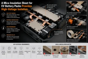
A Mica Insulation Sheet for EV Battery Packs Provides High-Voltage Isolation
EV battery packs contain hundreds or thousands of electrically connected components. Busbars, terminals, fuse elements, contactors, service disconnects, voltage-sensing circuits, cooling plates, module frames, and the enclosure can sit only millimeters apart. Movement, vibration, burrs, weld spatter, loose hardware, deformation, or conductive contamination can create an internal short.
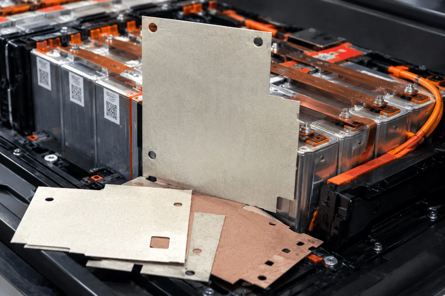
Mica sheets are used beneath busbars, around high-voltage junctions, between modules and structural metal, and inside contactor or fuse compartments. A die-cut part can provide a solid barrier while extending the creepage path around a conductor. Flexible mica tape can wrap complex busbars, cable transitions, or corners where a flat rigid panel cannot fit.
Electrical performance must be specified at part level. Useful requirements include dielectric breakdown strength, insulation resistance, test voltage, dwell time, leakage-current limit, minimum thickness, humidity conditioning, temperature, and performance after vibration and aging.
The sheet center is only one part of the dielectric system. Cut edges, holes, fastener zones, narrow webs, adhesive squeeze-out, surface contamination, and metal burrs may become the actual failure point. This is why precision die cutting and edge control matter as much as the raw mica certificate.
Why EV Packs Need Mica After Polymer Films Soften
Polycarbonate, PET, PI, Formax-type polypropylene, and other polymeric insulators can provide excellent normal-service dielectric performance. However, each polymer has a specific softening, melting, decomposition, and flame-response range. A severe thermal-runaway event can exceed those conditions.
Mica-based sheets are selected because the mineral layer can maintain a physical separation at much higher temperature. The barrier can continue to separate energized parts, protect the pack cover, or shield an adjacent module even after nearby organic layers have shrunk or carbonized.
This does not mean every mica laminate survives indefinitely. The binder, adhesive, reinforcement, and attachment may fail before the mica mineral. Engineers should distinguish continuous-use temperature, short-duration exposure, torch or flame performance, and post-exposure dielectric integrity.
A technically useful report shows shrinkage, cracking, delamination, burn-through time, cold-side temperature, mass loss, and retained insulation after the event. One unsupported maximum-temperature claim is not sufficient for an EV drawing.
A Mica Insulation Sheet for EV Battery Packs Resists Flame and Ejecta
Thermal runaway can release more than heat. A failing cell may emit hot decomposition gas, flammable vapor, jet flame, electrolyte droplets, molten material, and solid particles. These hazards can damage insulation, ignite polymer frames, contaminate high-voltage surfaces, or heat the next cell through an exposed edge.
Mica can act as a flame-facing and particle-resistant layer. It is frequently considered for vent corridors, module walls, pack perimeters, busbar shields, and the underside of the battery-pack cover. Rigid mica provides stable coverage; flexible mica can follow stamped surfaces and irregular geometry.
The barrier should protect the receiving surface rather than block the cell pressure-relief vent. A blocked vent can increase pressure or redirect the jet toward another cell. Vent routing, lid spacing, relief paths, and shield geometry must be designed with the mica part.
Direct jet locations may require greater thickness, mechanical support, glass reinforcement, a shaped deflector, or a hybrid mica-aerogel structure. Small-scale flame ratings cannot substitute for vent-impingement and module tests.
Why Pack Covers Use a Mica Insulation Sheet
In many cell layouts, vented gas and flame travel upward. The pack lid may be a large aluminum or steel panel located near wiring, structural adhesives, floor components, or the passenger compartment. A mica under-lid barrier can reduce burn-through risk and slow heat transfer into those areas.
The useful coverage is not only directly above the trigger cell. A vent plume may strike the lid and spread laterally along ribs, seals, gaps, bolt lines, or openings. The mica liner should cover the predicted flow and radiation footprint.
Rigid panels are suitable for broad flat lids, while flexible or segmented sheets can conform to stamped structures. Attachment may use pressure-sensitive adhesive, mechanical retention, clips, or a hybrid method. The adhesive is a separate material that must be evaluated for heat, aging, and flame exposure.
Testing should reproduce the real lid material, unsupported spans, attachment, vent distance, joints, and enclosure pressure. A mica sheet tested on a thick laboratory steel plate may behave differently when bonded across a thin automotive cover.
Why Module Walls and Perimeters Use Mica Insulation
Mica panels can create a fire and dielectric boundary between modules or between the cell array and enclosure. These barriers can help limit direct flame transfer, protect wiring channels and cooling components, and prevent energized parts from contacting the pack wall after mechanical deformation.
Module-level mica is especially useful where a rigid, stable boundary is required. It can be die-cut with openings for harnesses, coolant lines, fasteners, and locating features. Every opening, however, becomes a potential heat, flame, or creepage bypass.
The design should consider pressure and structural loading. A large unsupported mica panel can crack during vibration or assembly. A reinforced laminate, controlled support spacing, or a mica-PC composite may improve durability.
Current regulatory development is increasing attention on robust, system-level thermal-propagation performance. The proposed 05 series of amendments to UN Regulation No. 100 includes improved thermal-propagation procedures and transition provisions. This regulatory direction encourages pack makers to use stable compartment and cover barriers, while still requiring validation of the complete rechargeable energy storage system.
Can a Mica Insulation Sheet Protect Individual EV Cells?
Yes, mica can be placed between individual cells, particularly when the required functions include flame shielding, electrical separation, puncture resistance, or a rigid high-temperature surface. Prismatic and pouch cells may use broad-face die-cut sheets; cylindrical packs may use row partitions, sleeves, or group barriers.
Mica is not always the best standalone material when the dominant objective is maximum thermal resistance in a very thin gap. Aerogel usually provides lower thermal conductivity per millimeter. A mica-only barrier may still transfer enough heat to the neighboring cell if thickness, exposure, and cell energy are severe.
For high-energy modules, a hybrid construction can place mica on the hot side for flame and particle resistance and aerogel behind it to slow conductive and radiative heat transfer. Silicone foam may be added to manage cell swelling and stack pressure.
The correct material stack depends on cell chemistry, capacity, state of charge, facing area, vent direction, compression, cooling, and the module acceptance criterion. The part should be tested at the minimum production thickness and the worst credible installed condition.
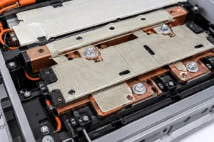
How a Mica Insulation Sheet for EV Battery Packs Supports Busbar Safety
Busbars connect cells and modules at different electrical potentials. During normal operation, the mica provides dielectric isolation. During thermal runaway, the same part can reduce flame exposure and keep conductive debris from reaching the busbar-to-structure gap.
A busbar insulator may include terminal windows, slots, folds, locating holes, and reinforced edges. Flexible mica tape can wrap narrow or curved conductors, while rigid laminates can protect broad flat areas.
The part should maintain creepage and clearance after aging, vibration, heat, and assembly. Adhesive flow, a cracked fold, loose fastener, or cut-edge delamination can reduce the real isolation path.
Some designs combine mica with flame-retardant polycarbonate. Mica provides the high-temperature surface, while PC adds puncture resistance, shape retention, clean edges, and a robust dielectric skin around metal hardware.
Why EV Packs Use Mica With Silicone Foam
Mica is relatively rigid and has limited capacity to absorb cell swelling or large tolerance variation. Prismatic and pouch-cell stacks often need a compliant layer that manages pressure throughout charge-discharge cycling and aging.
Silicone foam can provide that compliance. A mica-plus-silicone-foam pad can combine flame and electrical protection with a controlled compression curve. Industry suppliers have developed composite pads specifically for thermal-runaway mitigation and cell-swelling management.
The layer order and stiffness must be engineered. A foam that is too soft may allow movement; a foam that is too stiff may overload the cell or crack the mica. Edge seams, adhesive layers, and local ribs can create nonuniform pressure.
The complete stack should be cycled through the expected compression range and temperature. Thermal-runaway testing should use the installed thickness and aged mechanical condition.
Why EV Packs Use Mica With Aerogel
Mica and aerogel solve different parts of the same thermal-runaway problem. Mica retains structure under flame and provides dielectric protection. Aerogel creates high thermal resistance across a thin interface.
A hybrid barrier can use mica as the flame-facing layer and aerogel as the insulating core. This can be valuable beneath pack covers, near module boundaries, around vents, and between high-energy cells.
The combination is not automatically better. A rigid mica facing can create an edge bridge; full-face adhesive can increase contact and heat transfer; poor compression can crush the aerogel. The hybrid part must be designed and tested as one laminate.
Buyers should compare cold-side temperature, burn-through, particle erosion, installed thickness, compression, mass, and part cost—not simply compare the mica and aerogel datasheets separately.
Why EV Packs Use Mica With Flame-Retardant Polycarbonate
Flame-retardant polycarbonate is widely used for structural dielectric parts, terminal covers, busbar barriers, module liners, and large die-cut insulation because it provides puncture resistance, clean processing, and dimensional stability.
Mica adds a high-temperature surface that can remain protective during severe heat and flame. A composite can use PC for the structural geometry and mica at the expected hot zone.
The design should prevent the PC from becoming the first exposed layer in a direct jet unless the specified grade and construction have been validated. UL 94 V-0 polycarbonate classification is useful for material selection but does not prove battery-jet or pack-level performance.
Lamination must control bubbles, edge lifting, adhesive registration, thickness, and thermal expansion. Different coefficients of thermal expansion can produce curling or delamination during heat cycling.
Why Mica Is Chosen Instead of Only Metal Fire Shields
Metal shields can reflect heat, resist particles, and provide structural strength, but metal is electrically conductive and can transfer heat rapidly. It may also create an arc or short-circuit hazard near high-voltage components.
Mica provides a nonconductive barrier and can be lighter and easier to die-cut into local shapes. It can also be laminated to metal where the structure needs both mechanical strength and dielectric separation.
Metal fasteners, edges, and seams remain heat paths. A metal-plus-mica design must prevent direct metal contact and preserve creepage around holes.
The choice is not necessarily mica or metal. A layered shield can use metal for impact and pressure resistance, mica for dielectric and flame protection, and aerogel for additional thermal resistance.
Muscovite or Phlogopite: Why the Mica Grade Matters
Muscovite is commonly associated with excellent dielectric properties and dimensional stability. Phlogopite is often chosen for higher-temperature and chemical-resistance requirements.
A busbar or junction-box part may prioritize thinness, dielectric strength, and punch quality, making one muscovite construction suitable. A vent-facing or under-lid barrier may require the temperature capability of a phlogopite-based grade.
Binder and reinforcement can be more important than the mineral name. A phlogopite sheet with a weak adhesive may fail before a well-designed muscovite laminate in a moderate exposure zone.
The specification should identify the exact grade, binder, reinforcement, thickness, and supplier. Approval should be based on test data from the finished construction.
Why Mica Thickness Is Application-Specific
Increasing thickness can improve dielectric margin, stiffness, burn-through time, and resistance to flame and particle erosion. It also increases mass, cost, and package height and may reduce flexibility.
A thin adhesive mica tape may be suitable for local busbar insulation. A thicker rigid sheet may be required under the pack lid or across a module wall. A cell-to-cell barrier may use mica in combination with aerogel or foam.
Specify minimum finished thickness rather than only a nominal average. Pressing, grinding, lamination, film, adhesive, and manufacturing tolerance can create thinner local regions.
Holes, bends, unsupported spans, edge notches, and fastener loads may require local reinforcement or larger radii. Qualification samples should represent the minimum thickness and worst-case geometry.
Why Binder and Reinforcement Matter in EV Mica Sheets
Reconstituted mica paper requires a binder and often a reinforcing carrier. Silicone binders can provide high-temperature flexibility; epoxy systems can create stiff structural boards; glass fabric can improve tensile strength and puncture resistance.
More binder can improve handling and die-cut toughness but may reduce high-temperature integrity, increase smoke, or change flame behavior. The mica mineral may survive while the part loses mechanical support.
Reinforcement adds strength but can change thermal conductivity, thickness, dielectric performance, and cut quality. Two sheets with the same nominal mica content can behave differently because their carrier systems differ.
The complete bill of materials must be controlled through PPAP and change management. Changes to binder percentage, fabric, film, or adhesive may require revalidation.
Why Adhesive-Backed Mica Improves EV Assembly
Adhesive backing helps operators or automation place the mica accurately and hold it in position before the pack or module is fully assembled. It can reduce fasteners and simplify installation on lids, walls, busbars, and junction boxes.
The adhesive must match the substrate and environment. Aluminum, painted metal, stainless steel, polymer frames, and coated busbars have different surface energies. Heat, humidity, vibration, electrolyte exposure, and flame can reduce bond strength.
Full-face adhesive gives maximum initial contact but adds a continuous polymer layer and may increase heat transfer. Selective adhesive zones can reduce mass and thermal bridging while maintaining alignment.
Release liners, pull tabs, adhesive keep-out areas, and application pressure should be designed for production. A mica part that is difficult to peel and place will create wrinkles, cracks, contamination, and takt-time problems.
Why Precision Die Cutting Matters for Mica Protection
Mica-based laminates can crack, delaminate, fray, or release dust when they are converted. Sharp internal corners, narrow webs, unsupported holes, and small bend radii concentrate stress.
The drawing should define hole sizes, edge distances, corner radii, adhesive registration, liner split, pull tabs, bend zones, flatness, edge-quality limits, cleanliness, and packaging orientation.
Flatbed, rotary, CNC, stamping, and other processes may be used depending on grade, thickness, geometry, and volume. Tool sharpness, clearance, support liner, cut pressure, and dust extraction must be controlled.
A material that passes flame and dielectric tests can still fail in service if a punched edge is cracked or a terminal cutout removes too much coverage. Prototype the final laminate before freezing the pack drawing.
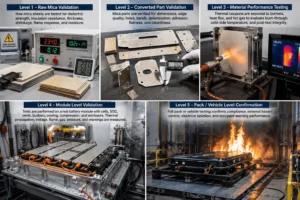
Why EV Mica Parts Need Multi-Level Validation
Level 1 verifies the raw mica construction: thickness, density or areal mass, dielectric strength, insulation resistance, binder content, mechanical strength, high-temperature shrinkage, flame response, and moisture behavior.
Level 2 verifies the converted part: dimensions, edges, holes, bends, delamination, adhesive peel, liner release, puncture, flatness, cleanliness, and packaging.
Level 3 uses thermal coupons, burners, heat flux, hot gas, or impingement to compare burn-through, cold-side temperature, particle damage, and post-test integrity.
Level 4 uses the representative battery module with the real cell, state of charge, vents, busbars, cooling structure, compression, and enclosure. It measures thermal propagation, voltage, flame, gas, pressure, and warning.
Level 5 confirms pack or vehicle performance. Only the complete system can demonstrate regulatory compliance, external hazard control, electrical isolation, and occupant-warning performance.
Why Current EV Safety Trends Increase Mica Demand
Battery packs are becoming more integrated. Cell-to-pack and cell-to-chassis architectures remove some traditional module walls and place more energy inside a continuous structure. Thin fire and dielectric barriers therefore become more strategically important.
Higher system voltage increases the value of robust insulation around conductors and metal structures, even though the individual cell voltage remains much lower. Fast charging and higher energy density also increase the importance of stable thermal and electrical separation.
The 05 series amendments proposed for UN Regulation No. 100 strengthen thermal-propagation assessment and include transition provisions beginning in 2027. This does not prescribe mica, but it increases demand for validated materials and barriers that support warning and hazard-control objectives.
The market is also moving toward multifunctional composites—mica plus foam, mica plus aerogel, or mica plus structural dielectric films—because one material rarely meets every mechanical, thermal, and electrical requirement.
Common Mistakes When Using a Mica Insulation Sheet for EV Battery Packs
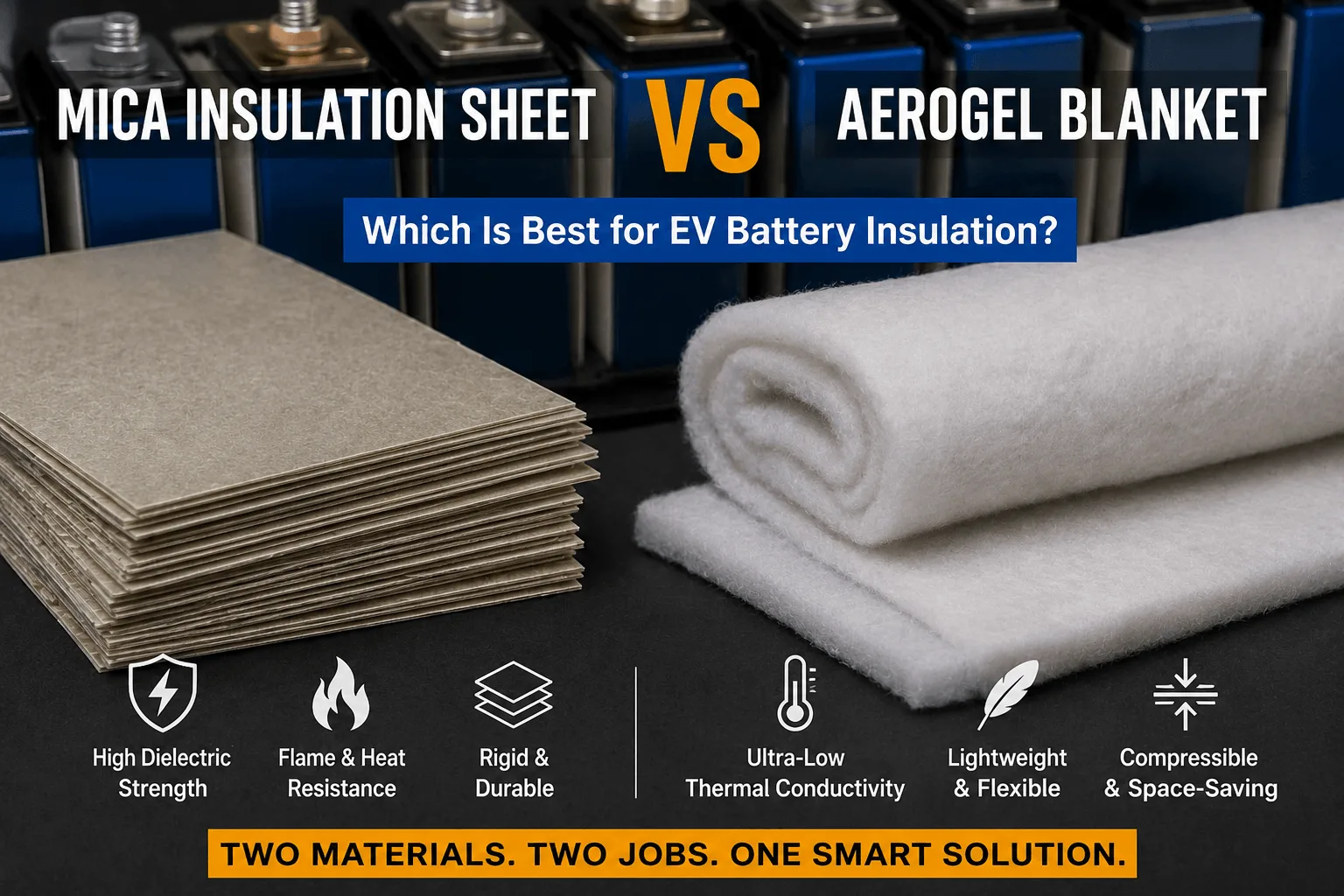
The first mistake is treating mica as the lowest-conductivity option. If the main objective is slowing broad-face conduction between cells, aerogel or a hybrid barrier may provide better performance.
The second mistake is blocking a pressure-relief vent. Mica should shield the receiving surface while the pack preserves a controlled gas path.
The third mistake is relying on a material UL 94 rating as proof of thermal-runaway protection. UL 94 is a small-scale flammability classification for a specified material and thickness, not a battery jet-flame or pack-level test.
The fourth mistake is ignoring metal heat bridges and uncovered edges. Heat can bypass the central sheet through busbars, frames, cooling plates, bolts, and gaps.
The fifth mistake is changing mica type, binder, adhesive, thickness, reinforcement, or converter after testing without technical review.
How to Specify a Mica Insulation Sheet for EV Battery Packs
Identify the function and location first: cell barrier, module wall, busbar insulation, junction box, pack perimeter, pack lid, or vent corridor.
Specify mica type, natural or reconstituted construction, binder, reinforcement, rigid or flexible format, thickness and tolerance, density or areal mass, dielectric strength, insulation resistance, temperature exposure, flame classification, and approved supplier.
The drawing should include protected areas, voltage zones, vent and terminal keep-outs, holes, radii, minimum webs, bends, adhesive pattern, liner split, pull tabs, edge quality, cleanliness, labeling, and packaging.
Add validation criteria, sampling, lot traceability, PPAP level, and formal change-control conditions. The specification must cover the finished die-cut component.
RFQ Checklist for a Mica Insulation Sheet for EV Battery Packs
Provide pack voltage, cell format, module layout, protected component, vent location, expected flame or heat exposure, available thickness, electrical-clearance requirement, substrate, mounting method, annual volume, and target production location.
Send PDF or CAD drawings with dimensions, tolerances, holes, bends, edge distances, adhesive zones, liner split, pull tabs, orientation, labels, and packaging.
State dielectric test voltage, temperature and flame requirements, environmental aging, restricted-substance requirements, prototype quantity, validation schedule, and PPAP level.
Describe the current problem—cracking, delamination, adhesive failure, burn-through, short-circuit risk, or assembly difficulty—so the converter can recommend the correct rigid, flexible, adhesive-backed, or composite construction.
Why Boost Insulation Is Positioned for Custom Mica EV Parts
Boost Insulation’s current website describes the company as a China-based EV battery insulation and precision die-cut manufacturer with IATF 16949 and ISO 9001 quality systems. It promotes DFM support, in-house tooling, cleanroom lamination and die cutting, APQP and PPAP support, and lot traceability.
The site also states suitable custom parts can be held to tight dimensional tolerances and that rapid prototypes can be produced within 48 hours. Its portfolio includes EV dielectric insulation, flame-retardant polycarbonate, aerogel, silicone sheets, thermal pads, films, and adhesives.
For a mica project, the engineering team can review grade, thickness, rigid or flexible format, adhesive placement, foam or PC lamination, edge reinforcement, die-cut geometry, inspection, electrical testing, packaging, and volume-production feasibility.
A useful inquiry should include the module, busbar, pack-cover, or enclosure drawing together with the voltage, temperature, flame exposure, target thickness, assembly method, annual volume, and test plan.
| Need a custom mica barrier, busbar insulator, or pack-lid part?
Send Boost Insulation your module, busbar, pack-cover, or enclosure drawing with the voltage, temperature, flame exposure, thickness, adhesive needs, test plan, annual volume, and PPAP requirements. The engineering team can review mica, flame-retardant PC, silicone foam, aerogel, films, adhesives, and die-cut options. Visit boostinsulation.com to upload a drawing or request a quote |
Frequently Asked Questions
Why is mica used instead of only plastic insulation?
Plastic insulation is effective during normal operation, but many polymers soften or decompose under severe battery-failure heat. Mica can maintain a dielectric and physical barrier at higher temperature.
Can mica prevent thermal runaway propagation?
Mica can delay heat and flame transfer and protect structures, but it cannot independently guarantee non-propagation. The complete cell, barrier, venting, cooling, and pack geometry must be tested.
Is mica used between every EV battery cell?
Some prismatic and pouch packs use cell-level mica or mica composites. Cylindrical packs more often use row, group, module, or lid barriers. Placement follows the dominant heat and vent paths.
Is mica better than aerogel?
They perform different functions. Mica provides flame resistance and high-temperature dielectric integrity; aerogel provides lower thermal conductivity. Many systems combine both.
Can mica be combined with silicone foam?
Yes. Silicone foam can manage swelling and tolerance, while mica provides a flame and dielectric surface. The stack must be tested under installed compression.
Does mica need UL 94 V-0?
Project requirements vary. Some finished mica laminates have UL 94 classifications. Verify the exact grade and thickness, and do not treat the rating as pack-level proof.
Can mica insulation sheets be adhesive-backed?
Yes. Pressure-sensitive adhesive can simplify installation, but substrate compatibility, heat, humidity, aging, and flame exposure must be validated.
What information is needed for a custom mica part?
Provide the CAD or PDF drawing, thickness, voltage, temperature and flame requirements, adhesive areas, tolerances, annual volume, packaging, and validation plan.
Technical References
- Boost Insulation. EV battery insulation, precision die cutting, DFM, rapid prototyping, APQP, PPAP, and traceability capabilities. Source
- United Nations Economic Commission for Europe. Proposal for the 05 Series of Amendments to UN Regulation No. 100, including improved thermal-propagation requirements and transition provisions. Source
- United Nations Economic Commission for Europe. UN Regulation No. 100, Revision 3. Source
- Electrolock. Thermal Runaway Protection in EV Batteries: The Role of Mica. Source
- E-Mobility Engineering. Battery Thermal Barriers: mica sheets as thermal and electrical insulation in e-mobility packs. Source
- Saint-Gobain Tape Solutions. Thermal Runaway Protection Solutions Enhance EV Safety, including mica/foam composite barriers. Source
- Saint-Gobain Tape Solutions. Understanding the Benefits of Mica Tape in EV Applications. Source
- Bai, Q. et al. Influence of Insulation Material Thickness on Spread of Thermal Runaway in a Battery Module. Processes, 2023. Source
Related Posts:
Is a Mica Insulation Sheet Better Than Aerogel for EVs?
What Is a Mica Insulation Sheet for EV Battery Packs?
How to Choose EV Battery Cell Insulation Pads?
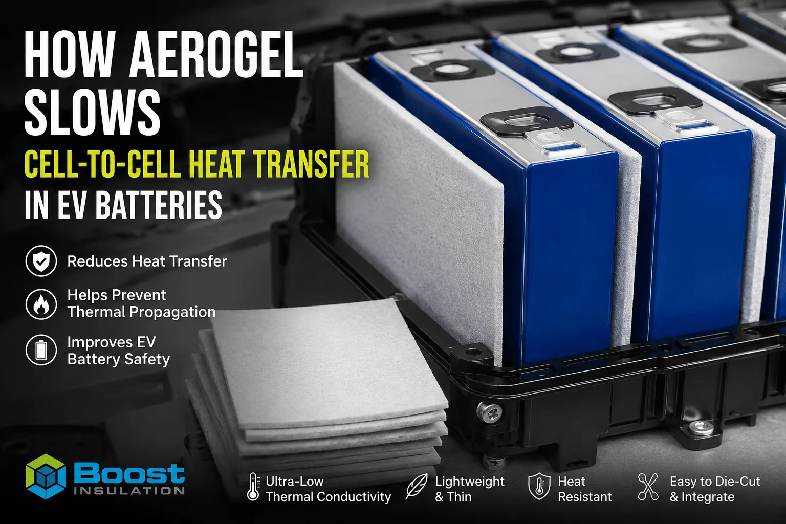
How Does Aerogel Slow Cell-to-Cell Heat Transfer in EVs?
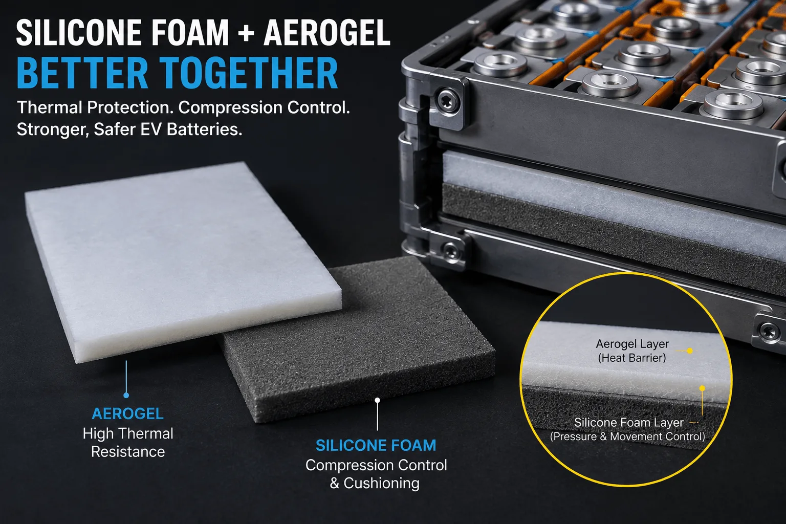
How Does Silicone Foam Work With Aerogel Barriers?
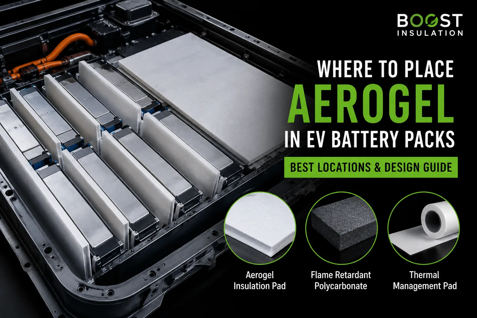
Where Is Aerogel Used Inside Modern EV Battery Packs?
 betty wong