
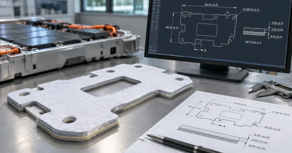
How to Specify Die-Cut Aerogel Insulation in CAD Drawings
Table of Contents
⚑ QUICK ANSWER
What Should a Die-Cut Aerogel Insulation CAD Drawing Include?
The drawing must define a verifiable finished component, not just its perimeter. A practical package combines a dimensioned PDF, machine-readable geometry, material and laminate specifications, and inspection instructions. The product engineer owns functional acceptance; the converter confirms whether the specified construction can be made repeatably. This division prevents a manufacturable-looking outline from being mistaken for a qualified thermal barrier.
Table 1 — Aerogel insulation CAD drawing requirements
| Drawing element | What to specify | Engineering purpose | Verification method |
| Identification | Part number, revision, units, projection | One controlled definition | Document comparison |
| Material | Approved grade and specification revision | Prevent substitutions | Certificate and traceability |
| Construction | Core, facings, adhesive, liner, seal | Define finished stack | BOM and section review |
| Geometry | Profile, openings, orientation | Fit and thermal coverage | Profile inspection |
| Thickness | State, contact load, locations | Comparable measurements | Defined thickness method |
| CTQ features | Datums, tolerances, keep-outs | Protect critical interfaces | Fixture or vision inspection |
| Quality | Edge, debris, records, deviations | Objective acceptance | Approved control plan |
Industry Insight 1 — A CAD outline is not a manufacturing specification. A DXF can transmit cutting geometry while omitting layer identity, thickness state, inspection restraint, and acceptance evidence. Why it matters: two suppliers can make visibly similar pads that are not interchangeable. Action: issue a controlled PDF drawing and specification set alongside the geometry file.
Which CAD Files and Supporting Documents Should Engineers Provide?
Use a PDF drawing as the human-readable, revision-controlled authority for dimensions and notes; DXF/DWG for 2D cutting paths; and STEP when mating surfaces, assembly envelopes, or installation constraints benefit from 3D context. Add an approved material specification, laminate BOM, inspection plan, and applicable customer quality requirements. Define which file governs if dimensions disagree; do not silently let a cutter’s imported DXF override the released drawing.
A useful release manifest records filename, part number, revision, units, intended use, and approver. Put manufacturing aids such as nesting layouts and tool-compensation paths under supplier process control, not into the customer’s nominal product definition. For geometry, separate cut, score, kiss-cut, print, and reference-only layers when those operations are present. Color alone is an unreliable definition unless a controlled legend explains it.
Industry Insight 2 — File authority is a quality characteristic. When a PDF is Rev C but the DXF is Rev B, the dispute is not a drafting inconvenience; it can change fit and barrier coverage. Action: require a release manifest and supplier acknowledgment of the governing revision before tooling.
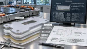
How to Specify Aerogel Material Grades and Laminate Construction
A material callout should identify the approved composite grade and the document that defines it, rather than saying only “aerogel sheet”. Aerogel cores can differ in reinforcement, facing, handling behavior, compression response, and particle release. Reference the approved supplier specification and its revision; do not assume that the generic material name establishes thermal, dielectric, or high-temperature performance.
Table 2 — Material and laminate construction callouts
| Layer or feature | Required specification | Drawing representation | Inspection evidence |
| Aerogel core | [GRADE], [SPEC-ID], [REV] | Section A-A, layer 1 | Lot certificate |
| Upper facing | [FILM GRADE], orientation | Section A-A, layer 2 | BOM / visual check |
| Lower facing | [FILM GRADE], orientation | Section A-A, layer 3 | Construction record |
| PSA zone | [ADHESIVE SPEC], pattern | Detail B and zone boundary | Registration inspection |
| Release liner | [LINER SPEC], split/tab | Supply-state detail | Peel/handling check |
| Perimeter seal | [SEAL SPEC], coverage | Detail C, continuous path | Seal inspection |
An illustrative material note is: “AEROGEL CORE PER [SPEC-ID], REV [REV]; APPROVED SOURCE [SUPPLIER/GRADE]. NO SUBSTITUTION WITHOUT CUSTOMER ENGINEERING APPROVAL.” For a laminate, use a numbered cross-section and a BOM that distinguishes retained installed layers from temporary supply liners. If the core thickness is critical, specify how it will be verified rather than deriving it from total laminate thickness by assumption.
How to Dimension Free-State, Finished, and Installed Thickness
Thickness is a state-dependent requirement for many compressible aerogel composites. Define whether the dimension applies to incoming core, converted part without removable liner, delivered part with liner, or installed stack under a specified compression condition. State contact pressure or fixture load, dwell, conditioning, measurement locations, and the acceptance statistic when relevant. An undefined “2.0 mm ± tolerance” can produce conflicting inspection results without either party making a measurement error. For upstream material selection rather than drawing notation, see Boost’s aerogel thickness guide.
Table 3 — Thickness and compression specification matrix
| Thickness state | Drawing definition | Measurement condition | Acceptance consideration |
| Core, free-state | Unlaminated approved core | [METHOD], [CONTACT LOAD] | Grade and lot screening |
| Finished part | Retained layers, liner excluded | [METHOD], [LOCATIONS] | Converted-part tolerance |
| Delivered part | Includes temporary liner if needed | [SUPPLY METHOD] | Packaging / feed clearance |
| Installed part | Assembly-restrained stack | [FIXTURE], [FORCE], [DWELL] | Fit and functional minimum |
| Minimum functional | Worst-case retained barrier | [VALIDATED CONDITION] | Thermal design requirement |
Example thickness note A: “FINISHED THICKNESS EXCLUDES REMOVABLE RELEASE LINER; MEASURE AT LOCATIONS T1–T5 PER [METHOD-ID], REV [REV], UNDER [CONTACT PRESSURE].”
Example thickness note B: “INSTALLED THICKNESS SHALL BE VERIFIED IN [ASSEMBLY FIXTURE] AFTER [DWELL] AT [CLAMP LOAD]; ACCEPTANCE PER [ASSEMBLY SPEC].”
Example thickness note C: “CORE THICKNESS SHALL NOT BE INFERRED SOLELY BY SUBTRACTING NOMINAL FACING THICKNESSES FROM TOTAL LAMINATE THICKNESS.”
Industry Insight 3 — A thickness tolerance without a measurement method is ambiguous. Soft pads can give different readings under different contact forces. Action: freeze the fixture, load, dwell, locations, and decision rule together with the tolerance.
Industry Insight 4 — Installed thickness is a separate engineering state. The module clamp load, cell swelling allowance, and laminate construction may change thickness after installation. Action: maintain separate drawing and assembly requirements, with evidence connecting the two; never substitute free-state measurements for installed verification.
How to Apply Datums, GD&T, and Critical Tolerances
Choose datum features from the actual location scheme: a stable reference edge, locating slot, carrier feature, or defined assembly fixture. A flexible pad may deform when lifted, stretched, or clamped, so its inspection setup must reproduce the agreed reference condition. ASME Y14.5 and ISO 1101 provide geometric specification languages, but neither removes the need to define an appropriate restrained or unrestrained measurement state for the particular part.
Table 4 — Datum and tolerance strategy
| Design feature | Functional requirement | Drawing approach | Verification concern |
| Primary locating edge | Repeatable X position | Datum B if functionally justified | Edge support and curl |
| Secondary notch | Prevent reversed placement | Datum C or controlled profile | Feature distortion |
| Pad broad face | Assembly seating | Defined support / restraint condition | Non-rigid free-state shape |
| Vent clearance | No interference at worst case | CTQ edge-to-keep-out dimension | Stack-up and registration |
| Adhesive zone | Hold without exposed adhesive | Pattern location to datum scheme | Lamination drift |
| Outer profile | Assembly fit | General profile tolerance as applicable | Fixture influence |
A practical datum example for a prismatic-cell pad might use the supported cell-facing surface as an inspection setup, a long locating edge as datum B, and an asymmetric notch as datum C—only if those references match how the assembly locates the pad. Do not label an imaginary ideal plane as a datum feature without defining the physical feature or datum target and how the part is supported.
Industry Insight 5 — Critical dimensions should follow functional risk. A vent keep-out or minimum protected edge may warrant stronger control than a cosmetic perimeter. Action: mark CTQ features on the drawing and tie each to its own method and acceptance record.
Industry Insight 6 — Flexible parts need an explicit inspection condition. A tolerance applied to an unsupported pad may be impossible to reproduce. Action: agree fixture contact surfaces, permissible restraint, part orientation, and whether dimensions are checked before or after liner removal.
How to Specify Edge Sealing and Particle Containment
Define the seal as a functional construction feature, not an unqualified instruction to “seal edges.” Show the seal path in a plan view and the overlap or encapsulation in a section/detail view. Specify any allowable exposed core, continuity requirement, seam width, local step, excluded regions, and inspection method. Particle-control criteria should reference a customer-approved procedure; a visual “dust-free” note is not a measurable acceptance limit. The separate particle-shedding measurement guide addresses test development in more detail.
Example callout: “PERIMETER ENCAPSULATION SHALL BE CONTINUOUS EXCEPT IN ZONE [ID]; EXPOSED CORE AND SEAL DISCONTINUITIES SHALL MEET [EDGE SPEC], REV [REV].” A second note may define a seal-width range under a named inspection fixture, rather than prescribing an unsupported universal value. Where particle shedding matters, refer to the approved handling exposure, collection metric, threshold, and reporting basis.
Industry Insight 7 — Edge sealing changes both cleanliness and functional geometry. A wide polymer seam can reduce exposed aerogel area or form a local ridge under compression. Action: dimension the seal boundary separately from the outer cut profile and assess its effect on installed thermal coverage.
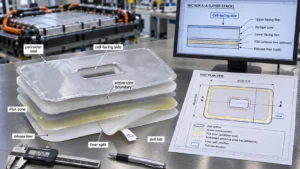
How to Show Adhesive Zones, Release Liners, and Multilayer Structures
Use a section view for layer order and a plan-view pattern for adhesive position. Define which side faces the cell, which layers remain installed, where adhesive is prohibited, and how the liner is removed. If a split liner or pull tab is required for assembly, dimension it as a supplied feature rather than confusing it with the final installed part. Identify whether adhesive registration is measured before or after liner removal. For material-function tradeoffs in hybrid stacks, see aerogel with polycarbonate insulation; this drawing guide addresses only how the selected stack is documented.
Table 5 — Edge-seal, adhesive, and coverage requirements
| Feature | Required callout | Potential failure mode | Inspection evidence |
| Perimeter seal | Path, overlap, exceptions | Open seam / exposed core | Visual or qualified test |
| PSA zone | Boundary and side | Adhesive in prohibited region | Vision / overlay |
| Liner split | Split position and removal order | Pad distortion on peeling | Assembly trial |
| Facing orientation | Cell-facing side / print | Reversed construction | Marking and BOM check |
| Active core boundary | Protected-area profile | Thermal coverage loss | Overlay to mating CAD |
| Layer registration | Offset limit by feature | Uncovered core or adhesive drift | Cross-section / vision |
Industry Insight 8 — Adhesive layers change the finished-part definition. Even a thin PSA can affect stack height, handling, heat paths, and liner-removal damage. Action: give adhesive and liner separate callouts and qualify the exact delivered construction.
How to Dimension Cutouts, Keep-Out Zones, and Active Thermal Coverage
Draw three boundaries when applicable: outer die-cut profile, active aerogel-core boundary, and functional keep-out envelope. A cutout may be necessary for a vent or terminal, yet its tolerance can reduce protected area at worst-case assembly position. Dimension the clearance to the actual mating feature, not merely to an arbitrary origin. The thermal team must determine acceptable uncovered regions from system analysis and validation.
Industry Insight 9 — The outer boundary is not necessarily the active thermal boundary. Seals, apertures, adhesive zones, and local core offsets can change the protected area. Action: release a distinct active-core contour and check its worst-case position against the cell and vent model.
How to Write Manufacturing-Ready Aerogel Drawing Notes
Good notes use an object, condition, requirement, and verification reference. Avoid phrases such as “high quality,” “minimal dust,” or “tight tolerance” without an agreed method. The following are illustrative language templates, not standard requirements; every bracketed item must be completed and approved for the program.
Table 6 — Twelve example engineering drawing notes
| Note ID | Example drawing note | Purpose / project input |
| N01 | MATERIAL: [GRADE] PER [SPEC-ID], REV [REV]. | Approved core identity |
| N02 | LAMINATE CONSTRUCTION PER SECTION A-A AND [BOM-ID], REV [REV]. | Layer control |
| N03 | FINISHED THICKNESS EXCLUDES REMOVABLE LINER; MEASURE PER [METHOD-ID]. | Thickness state |
| N04 | INSTALLED THICKNESS SHALL MEET [ASSEMBLY SPEC] AT [LOAD/DWELL]. | Compressed condition |
| N05 | INSPECT CTQ PROFILE WITH PART SUPPORTED IN [FIXTURE-ID]. | Restraint |
| N06 | EDGE SEAL SHALL FOLLOW DETAIL C; ACCEPT PER [EDGE SPEC]. | Seal acceptance |
| N07 | PSA SHALL BE PRESENT ONLY WITHIN ZONE ADH-1, DETAIL B. | Adhesive location |
| N08 | SUPPLY WITH [LINER-ID]; SPLIT AND TAB PER DETAIL D. | Removal design |
| N09 | INSTALL FACE MARKED “CELL SIDE” TOWARD [MATING SURFACE]. | Orientation |
| N10 | FEATURES FLAGGED CTQ REQUIRE RECORDED FIRST-ARTICLE RESULTS. | Inspection record |
| N11 | PARTICLE CONDITION SHALL MEET [METHOD/LIMIT] AFTER [EXPOSURE]. | Cleanliness method |
| N12 | MATERIAL OR PROCESS DEVIATIONS REQUIRE APPROVAL PER [CHANGE PROCEDURE]. | Change control |
For a formal release, check that every note has a defined noun, controlled reference, measurable outcome, and owner. If the test method is still under development, mark the requirement OPEN—NOT FOR PRODUCTION RELEASE, rather than replacing it with a vague “supplier to confirm.”
Example: A Complete CAD Drawing Specification for an EV Battery Aerogel Pad
Hypothetical engineering example — illustrative assumptions only, not Boost customer data or recommended universal limits. An OEM is developing a die-cut, film-faced aerogel barrier for a prismatic-cell module. The design includes a vent clearance, asymmetric locating notch, perimeter encapsulation, and a temporary PSA positioning zone. Its purpose is to demonstrate how to document requirements—not to certify thermal propagation performance.
Example drawing identification: Part AG-PAD-042; drawing DWG-AG-042; revision B; units mm; status PROTOTYPE—ENGINEERING REVIEW. Illustrative outer envelope: 160 × 90 mm. For drawing-format demonstration only, suppose the locating notch is 6 × 4 mm, the sealed band is nominally 3 mm, and a protected-edge clearance is nominally 8 mm. These are arbitrary teaching dimensions, not validated battery design recommendations. The exact core thickness, dimensional tolerances, compression load, and acceptance limits remain controlled project values: [CORE THICKNESS], [FINISHED TOLERANCE], [LOAD], [CRITERION].
Example drawing specification package
| Item / view | Drawing callout | Governing evidence |
| Plan view | Outer profile; notch; vent keep-out V1 | Dimensioned PDF + DXF |
| Section A-A | Core, upper/lower facings, retained adhesive | Approved laminate BOM |
| Detail B | PSA zone ADH-1; adhesive-free V1 | Overlay inspection |
| Detail C | Encapsulation path and exposed-core rule | Edge-seal procedure |
| Detail D | Removable liner split and pull tab | Assembly work instruction |
| CTQ schedule | V1 clearance; core coverage; seal continuity | First-article report |
| Thickness schedule | Finished and installed states | Methods [THK-01]/[ASM-02] |
Example section-view callout: Layer 1, upper protective facing [FILM-A]; Layer 2, aerogel composite core [AG-GRADE]; Layer 3, lower facing [FILM-B]; Layer 4, zoned PSA [PSA-1] on the designated side; temporary release liner [LINER-1] supplied but removed before assembly. Perimeter seal [SEAL-1] surrounds the defined core boundary. A revision-controlled BOM identifies each material and allowed source.
Example CTQ inspection matrix: CTQ-01, vent keep-out V1: overlay with mating CAD and check minimum clearance under approved restraint; CTQ-02, active-core coverage: compare core contour to required protected envelope; CTQ-03, seal continuity: inspect Detail C to [EDGE SPEC]; CTQ-04, installed thickness: verify in [ASSEMBLY FIXTURE] under [LOAD]. No numerical pass criterion is implied by this example.
Release decision: keep the drawing at prototype status until the customer approves the fixture, thickness method, core coverage acceptance, seal/particle method, and representative part validation. A supplier’s successful profile cut does not close those functional evidence gaps.

How to Link Drawing Requirements to Inspection and Acceptance Criteria
Every critical callout should have an evidence chain: drawing requirement → measurement setup → acceptance rule → retained record → release authority. Separate material-lot identity, finished-part dimensional inspection, assembly fit, and module-level performance. First-article inspection can establish dimensional conformance; it cannot by itself demonstrate thermal propagation resistance.
Table 7 — Drawing-to-inspection evidence matrix
| Drawing requirement | Inspection method | Acceptance criterion | Required record |
| Approved aerogel grade | Material ID / certificate review | Exact approved revision | Lot traceability |
| Finished thickness | [THK-01], defined contact load | [PART SPEC LIMIT] | Thickness results |
| Installed thickness | [ASM-02], specified fixture | [ASSEMBLY LIMIT] | Fixture report |
| Vent keep-out | Datum-based overlay | [MIN CLEARANCE] | CTQ dimensions |
| Seal continuity | [EDGE-01] | [SEAL RULE] | Images / result |
| PSA registration | Pattern overlay | [ZONE TOLERANCE] | Vision report |
| Particle release | [CLEAN-01], specified exposure | [CUSTOMER LIMIT] | Test report |
| Construction revision | BOM / traveler reconciliation | Matching approved revisions | Release checklist |
Industry Insight 10 — A drawing note must be verifiable. “No particles” and “perfect seal” do not define an inspection decision. Action: reference the approved procedure, detection threshold or observation rule, sampling plan, and disposition authority before supplier acceptance.
Fifteen Common Aerogel CAD Drawing Mistakes
- DXF only: no controlled product requirements; add a dimensioned PDF and revision manifest.
- Generic “aerogel” callout: material substitution risk; name the approved grade and specification.
- Core and total thickness conflated: stack may not fit; define both states separately.
- Unspecified thickness load: inconsistent results; prescribe measurement conditions.
- Installed thickness inferred from free-state: compression gap risk; validate in an assembly fixture.
- Unsupported datum scheme: nonrepeatable dimensions; define functional location and restraint.
- All dimensions marked CTQ: cost without benefit; prioritize risk-driving features.
- Seal width omitted: unknown active core area; dimension the seam and core boundary.
- No exposed-core criterion: uncertain edge acceptance; reference a seal inspection rule.
- PSA side not identified: reversed placement; show adhesive orientation in section and plan.
- Release liner treated as installed material: incorrect stack height; label supply-only layers.
- Vent keep-out based on nominal geometry: interference risk; review worst-case assembly stack-up.
- Cleanliness called “dust-free”: no decision rule; specify exposure and measurable limit.
- BOM and drawing revisions disagree: wrong construction; require release reconciliation.
- Production approval after a successful cut: functional evidence missing; close validation gates first.
Aerogel CAD Drawing Release and Supplier DFM Checklist
Release should be a documented decision, not an email saying the CAD “looks good.” Engineering must own safety and functional limits; the supplier must demonstrate process feasibility and agreed inspection capability. Use PASS / FAIL / OPEN for every item, and prohibit production release when an unresolved open item affects a CTQ function.
Table 8 — CAD release and supplier DFM checklist
| Review item | Required deliverable | Responsible party | Release decision |
| Governing files | PDF, geometry, manifest, revisions | Customer design | PASS / FAIL / OPEN |
| Approved stack | BOM, grades, source controls | Customer + supplier | PASS / FAIL / OPEN |
| Thickness states | Methods and acceptance limits | Mechanical / test | PASS / FAIL / OPEN |
| Datum and CTQ | Fixture, dimensions, stack-up | Design / quality | PASS / FAIL / OPEN |
| Seal / adhesive / liner | Details and assembly trial | DFM / assembly | PASS / FAIL / OPEN |
| Cutting feasibility | Tooling, edge, handling review | Converter | PASS / FAIL / OPEN |
| First-article evidence | CTQ measurements and deviations | Supplier quality | PASS / FAIL / OPEN |
| Functional validation | Customer-approved test results | OEM / integrator | PASS / FAIL / OPEN |
| Production controls | Traceability, change rules, packaging | Supplier + SQE | PASS / FAIL / OPEN |
Industry Insight 11 — DFM belongs before drawing freeze. Narrow bridges, unsupported cuts, liner removal, and seal geometry can be expensive to revise after tooling. Action: ask the converter to mark feasibility risks against the actual released drawing and return a controlled DFM disposition list.
Industry Insight 12 — Revision control is part of functional quality. A facing, adhesive, or seal change may invalidate prior thickness, cleanliness, or thermal evidence even when the outer DXF is unchanged. Action: link drawing, BOM, test reports, and approved supplier process revisions in the change-impact review.
How to Submit Aerogel CAD Drawings for Supplier DFM Review
Send the controlled PDF and DXF/DWG, relevant STEP assembly, approved material grade, laminate BOM, CTQ schedule, thickness measurement conditions, edge/particle requirements, adhesive and liner drawings, prototype quantity, forecast volume, packaging method, and requested quality documents. Flag any open design assumptions. For a separate treatment of assembly retention, refer to preventing aerogel pads from shifting. Ask the supplier to return feasibility, alternative tooling/handling proposals, inspection-method concerns, material substitutions, and unresolved risks separately—not to edit the customer’s product definition without approval.
Before tooling, agree which dimensions the converter can hold on representative material, how flexible parts will be measured, how seals and adhesive zones will be verified, and which prototype tests are owned by the OEM. For production transfer, control the material lot, die-cut method, laminate sequence, first-article results, and approved packaging. A process change may require correlation or requalification even if the nominal outline stays constant.
How Boost Insulation Can Support Custom Die-Cut Aerogel Parts
Boost Insulation’s aerogel product page describes aerogel-focused DFM review, precision cutting, CNC processing, and multilayer lamination with adhesive and protective films. These published capabilities make a drawing-led feasibility discussion relevant. The actual grade, seal method, achievable tolerance, inspection scope, and project documentation should be confirmed in the quotation and approved sample plan; a website description is not project-specific qualification evidence.
For a practical review, send the released drawing package plus application location, intended insulation function, compression envelope, prototype quantity, annual volume, and required verification. Request a written DFM response that identifies the manufacturing route, open questions, and proposed first-article evidence before committing to production tooling.
Frequently Asked Questions
What should an aerogel insulation CAD drawing include?
It should identify the approved aerogel grade and laminate BOM, dimension the outer profile and active core, define thickness states and measurement conditions, and show functional datums, cutouts, seal details, adhesive zones, and liner orientation. Critical features need acceptance methods, traceable records, and a controlled drawing revision. A cutting DXF is useful geometry, but it is not a complete product specification.
How do you specify aerogel insulation thickness on an engineering drawing?
State whether the requirement applies to core, finished laminate without removable liner, delivered construction, or installed compressed stack. Specify the measurement fixture, contact pressure or clamp load, dwell, conditioning, and locations where necessary. Assign the relevant acceptance limit to that state. Do not infer installed thickness from a free-state measurement or assume a universal compression factor across aerogel grades.
What tolerances should be used for die-cut aerogel insulation?
There is no universal tolerance for every aerogel composite. Set tolerances from assembly fit, vent clearance, functional coverage, material behavior, and the converter’s demonstrated process capability. Define how the flexible part is supported or restrained during inspection. Treat risk-driving dimensions as critical-to-quality and allow less restrictive general dimensions where appropriate; confirm the measurement method before freezing the drawing.
How should edge sealing be shown on an aerogel CAD drawing?
Show the perimeter seal in plan view and its overlap or encapsulation in a section or detail view. Dimension the seal boundary, identify exceptions and allowed exposed-core conditions, and reference an approved continuity or particle-control inspection procedure. Where the seal reduces the active core area, define both boundaries. A note saying only “seal all edges” does not establish measurable acceptance.
How do you specify adhesive-backed aerogel insulation in CAD?
Use a layer section to identify the adhesive grade and bonded side, then show the adhesive pattern and adhesive-free regions in a dimensioned plan view. Define liner material, split, pull tab, and removal orientation as supply-state features. State how adhesive registration and finished thickness are measured. Validate peel handling, assembly alignment, and the actual laminated construction rather than qualifying the core alone.
What is the difference between free-state and installed aerogel thickness?
Free-state thickness is measured under a specified low-load or defined contact condition outside the assembly. Installed thickness describes the material constrained by the actual module geometry and clamp or compression state. They can differ because of core compressibility, facings, adhesive, and assembly loads. Both measurements need named conditions and separate acceptance criteria when each is functionally important.
What CAD files are required for custom die-cut aerogel insulation?
A dimensioned, revision-controlled PDF should normally define the product; DXF or DWG supplies 2D cutting geometry, and STEP can clarify mating surfaces or installation constraints. Add the approved material and laminate specifications, BOM, inspection criteria, and RFQ quantities. Agree which file governs if discrepancies arise, and identify tool paths or nesting layouts as supplier manufacturing data rather than customer design geometry.
How can engineers verify that an aerogel insulation drawing is manufacturing-ready?
Run a joint design and supplier DFM review. Confirm approved construction, datum and thickness measurement conditions, CTQ tolerances, seal and adhesive details, functional coverage, tooling feasibility, and first-article inspection methods. Close unresolved safety- or function-critical items, then link the drawing revision to representative prototype and assembly validation evidence. A successful trial cut alone is not sufficient for production release.
Final Engineering Recommendations
Treat the drawing as a controlled agreement between design intent and measurable production output. Start with functional boundaries, define the exact material stack and thickness states, then add datums, section details, inspection methods, and release evidence. Review the package with the converter before tooling, and reserve thermal safety acceptance for representative component and system validation.
Engineering CTA: Preparing drawings for custom die-cut aerogel insulation? Share your PDF, DXF/DWG or STEP files, material specification, thickness conditions, edge and adhesive requirements, CTQ dimensions, and expected production volume with Boost Insulation for a project-specific manufacturing feasibility and quotation review.
Related Posts:
Why Do EV Battery Packs Use a Mica Insulation Sheet?
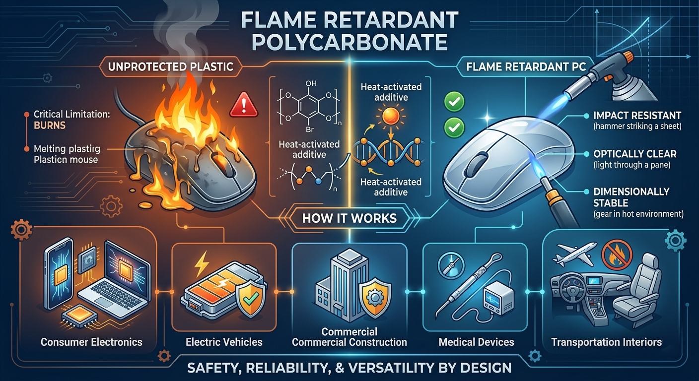
What Is Flame Retardant Polycarbonate and Why Does It Matter?

How Is a Mica Insulation Sheet Used on Module End Plates?

How to Select PC Film Thickness for Electrical Parts?

How Does a Mica Insulation Sheet Protect Battery Pack Lids?

What Is Battery Aerogel Insulation for EV Battery Packs?
 root