What Thermal Conductivity Should EV Aerogel Insulation Have?
Table of Contents
A supplier offers an aerogel sheet rated at 0.019 W/mK. Another quotes 0.024 W/mK at half the price. Which one will actually protect the next cell during thermal runaway? The number looks decisive, but without the test temperature, measurement direction, installed thickness, compression, facing films, adhesive, and module geometry, it can be more misleading than useful.
| For most EV cell-to-cell barriers, a practical screening target is an apparent through-plane thermal conductivity of about 0.017-0.025 W/mK at room temperature, with lower values generally preferred when test conditions are comparable. However, EV aerogel insulation should be selected by thermal resistance at the installed compressed thickness, elevated-temperature performance, edge and vent heat paths, and module-level propagation testing. A low datasheet value alone does not guarantee safety. |
EV Aerogel Insulation Thermal Conductivity: Quick Decision Matrix
| Screening Item | Practical Target | Why It Matters | Verification |
| Room-temperature k-value | About 0.017-0.025 W/mK | Initial comparison of similar battery-grade composites | Same method, temperature, direction, thickness, and pressure |
| Installed thermal resistance | R = installed thickness / k | Captures the effect of thickness | Test the finished laminate under compression |
| Elevated-temperature behavior | Cold-side temperature and time-to-threshold | Radiation, films, and structural stability change performance | Heat-flux or application-relevant test |
| System performance | Delay or no-propagation target | Includes vents, flame, metal bridges, and geometry | Representative module and pack test |
EV Aerogel Insulation Thermal Conductivity: The Direct Answer
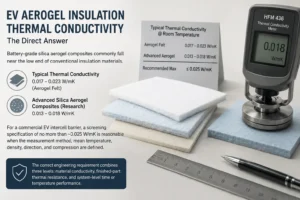
Battery-grade silica aerogel composites commonly fall near the low end of conventional insulation materials. Published battery work has reported aerogel felt around 0.017-0.023 W/mK, while advanced silica-aerogel composites in research may report values around 0.013-0.018 W/mK at room temperature. For a commercial EV intercell barrier, a screening specification of no more than approximately 0.025 W/mK is reasonable when the measurement method, mean temperature, density, direction, and compression are defined.
That does not mean every material above 0.025 W/mK is unsuitable, or that every material below 0.020 W/mK will prevent propagation. A 2 mm barrier at 0.024 W/mK may provide more thermal resistance than a 1 mm barrier at 0.018 W/mK. A low-conductivity bare core can also lose practical performance when compressed, cut, laminated with a continuous adhesive layer, or bypassed by hot gas and metal structures.
The correct engineering requirement combines three levels: material conductivity, finished-part thermal resistance, and system-level time or temperature performance. Procurement should never approve an EV aerogel barrier from one conductivity number alone.
Why EV Aerogel Insulation Thermal Conductivity Is Only a Screening Metric
Thermal conductivity, represented by k, describes how readily heat flows through a material under specified conditions. A lower k value indicates a stronger resistance to heat transfer per unit thickness. It is useful for comparing similar materials, but it is not the same as the thermal resistance of the installed part.
For a flat layer under simplified steady-state conditions, thermal resistance per unit area can be approximated as R = t/k, where t is thickness and k is thermal conductivity. A 1 mm layer with k = 0.020 W/mK has an idealized R-value of 0.05 m2K/W. Increasing the same material to 2 mm doubles the idealized resistance to 0.10 m2K/W.
Thermal runaway is not a steady-state, one-dimensional event. Heat also moves by radiation, hot gas, flame, ejecta, cell casing, busbars, cooling plates, frames, adhesives, and uncovered edges. The R = t/k relationship is valuable for first-stage comparison but cannot predict the exact propagation delay.
The business implication is important: the lowest k-value is not automatically the lowest-risk or lowest-cost solution. The best part is the minimum manufacturable stack that passes the target test with adequate production margin.
How to Measure EV Aerogel Insulation Thermal Conductivity
Ask the supplier to identify the test method. ASTM C518 and ISO 8301 describe heat-flow-meter methods for measuring steady-state heat transfer through flat specimens. Guarded hot plate methods, such as ISO 8302 or ASTM C177, may also be used. Results from different methods can be comparable when performed correctly, but they should not be mixed without reviewing specimen and calibration conditions.
The report should state specimen thickness, mean temperature, hot- and cold-plate temperatures, temperature gradient, density or areal weight, humidity condition, orientation, compression or contact pressure, and whether the specimen was a bare aerogel core or a completed laminate.
Porous materials are sensitive to boundary contact. A soft, uneven aerogel felt may create contact resistance between the specimen and test plates. Surface films and compression can change this contact. The reported number may therefore be an apparent conductivity for the tested assembly rather than a pure intrinsic property.
For supplier comparisons, request tests from the same laboratory or require the same standard, thickness range, temperature, and pressure. Comparing 0.018 W/mK measured on an uncompressed 10 mm coupon with 0.023 W/mK measured on a compressed 1.5 mm production laminate is not a valid ranking.
Room-Temperature EV Aerogel Insulation Thermal Conductivity
Room-temperature data is useful because it is widely available, repeatable, and suitable for material screening. A practical commercial target for reinforced battery aerogel is often approximately 0.017-0.025 W/mK, measured near 20-25 degrees Celsius under a defined method.
A value near 0.017-0.020 W/mK is strong for a reinforced flexible composite, provided mechanical durability and cleanliness remain acceptable. A value near 0.021-0.025 W/mK can still be fully suitable if the grade offers better compression stability, lower dust, stronger facings, tighter thickness tolerance, or a more efficient installed stack.
Values significantly below 0.015 W/mK may be possible in specialized or laboratory aerogels, but buyers should confirm whether the result belongs to a fragile monolithic sample, a vacuum condition, a low-density research specimen, or a commercially reinforced battery part.
The best room-temperature number should be treated as the beginning of qualification, not the end.
High-Temperature EV Aerogel Insulation Thermal Conductivity
Thermal-runaway exposure occurs far above room temperature, and the effective heat-transfer behavior can change. Radiation becomes more significant as surface temperature rises. Carrier fibers, opacifiers, reinforcement, films, adhesives, and edge seals can affect cold-side temperature even if the core aerogel remains stable.
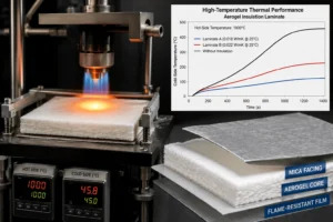
Ask for conductivity or thermal-resistance data at several mean temperatures when available. At minimum, request high-temperature heat-flux or hot-side/cold-side test curves for the exact laminate. These curves show whether the barrier continues to create useful time as the hot-side temperature rises.
A room-temperature conductivity of 0.018 W/mK does not prove that the finished part will outperform a 0.022 W/mK competitor during a high-temperature event. The lower-value core may use a film that shrinks, an adhesive that softens, or a carrier that collapses. The stronger laminate may retain thickness and coverage longer.
For severe vent and flame zones, test direct impingement or use a flame-resistant facing such as mica or coated high-temperature fabric. Conductivity data cannot replace jet, flame, or particle testing.
Through-Plane vs In-Plane Thermal Conductivity
Cell-to-cell aerogel pads are usually selected to resist heat moving through the pad thickness. This is the through-plane direction. Fiber orientation, lamination, compression, and reinforcement can make the material anisotropic, meaning conductivity differs by direction.
A supplier may report the most favorable direction without clearly identifying it. Drawings and technical data sheets should specify through-plane conductivity for the cell interface. In-plane heat spreading can still matter near edges, seams, and metal attachments, but it should not replace the principal through-thickness measurement.
For multilayer parts, the apparent through-plane result includes the aerogel core, facing films, adhesive, and contact interfaces. This completed-stack measurement can be more relevant than the bare-core number.
If the design uses shaped barriers, folded tabs, sleeves, or row partitions, test the heat-flow direction that reflects the installed geometry. A flat coupon can miss a conductive fold or compressed edge.
Installed Thickness Changes the Required Conductivity
Conductivity and thickness must be evaluated together. A design with only 0.8 mm of installed space may require a lower-conductivity grade than a design that can retain 2.0 mm. Conversely, a thicker but slightly higher-conductivity reinforced pad may offer better total resistance and manufacturing stability.
The drawing should define free-state thickness, tolerance, installed thickness range, assembly pressure, and end-of-life thickness. Do not write only “1.5 mm aerogel” without stating whether 1.5 mm is the incoming value or the compressed operating value.
Cell swelling can reduce the available thickness over vehicle life. Pouch and prismatic modules should model beginning-of-life and end-of-life stack pressure. Cylindrical modules should ensure shaped barriers do not move into cooling or vent channels.
Use the worst credible installed thickness when calculating first-stage thermal resistance and when conducting coupon or module tests.
How Compression Affects EV Aerogel Insulation Thermal Conductivity
Compression is not always negative. Controlled preload prevents gaps, improves positioning, and can stabilize the cell stack. However, excessive compression can increase solid-to-solid contact inside the porous structure and reduce the heat-flow distance. It may also crush edges or force adhesive into keep-out zones.
Request compressive stress-strain curves, compression set, recovery, and thermal data at representative pressure. A nominal conductivity measured with minimal pressure may not represent a clamped battery module.
Local compression is often more dangerous than average compression. Edge seals, film overlaps, pull tabs, adhesive stripes, locating ribs, frame tolerances, and uneven cell swelling can create thin hot spots. Pressure-sensitive film or thickness mapping during prototype assembly can reveal these areas.
If a silicone foam layer is added for swelling management, test the complete stack. A soft foam can distribute pressure effectively, but it can also drive the aerogel below its qualified thickness if the load path is not controlled.
EV Aerogel Insulation Thermal Conductivity by Cell Format
Prismatic cells have large facing areas, so the barrier must resist heat across a broad surface. A reinforced or encapsulated pad with consistent through-plane conductivity, flatness, and thickness is usually preferred. Edge coverage, top-vent clearances, busbars, and cooling plates require separate review.
Pouch cells need a smooth, compliant surface and uniform pressure. Thermal conductivity remains important, but mechanical uniformity and compression behavior can be equally decisive. A nominally superior low-k material that wrinkles or creates a hard seam can damage the pouch and produce inconsistent contact.
Cylindrical modules have smaller contact zones and open gas channels. Row or group barriers may need mechanical rigidity and shaped geometry. The dominant propagation path can involve vent gas and flame rather than direct conduction, so material conductivity is only part of the design.
Cell-to-pack and cell-to-chassis platforms reduce compartment walls and often demand thinner barriers. They also create long structural heat paths through trays and cooling plates. Thermal mapping should be completed before finalizing the conductivity target.
Does Cell Chemistry Change the Conductivity Target?
Chemistry does not directly change the physical conductivity of the aerogel, but it changes the energy and severity the barrier must handle. High-nickel NMC or NCA cells may produce rapid heat release and severe venting. Large-format LFP cells can still release substantial energy and expose a large facing area.
A more severe cell may require lower conductivity, greater installed thickness, stronger high-temperature facings, improved vent routing, or additional mica and structural barriers. A less severe cell does not automatically justify a cheaper or thinner pad; the final module geometry and acceptance criterion still control the decision.
State of charge is also critical. Published aerogel-barrier experiments have shown different propagation timing at different SOC even with the same material and thickness. Qualification should use the project-defined worst credible condition.
The thermal specification should therefore reference cell chemistry, capacity, format, SOC, trigger method, and test criterion rather than assigning one conductivity value to all platforms.
Finished Laminates Can Raise Apparent Conductivity
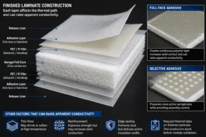
The production part may include aerogel felt, reinforcement, PET or PI film, adhesive, release liner, mica, PC film, printing, and edge sealing. Each layer changes the thermal path.
Full-face adhesive creates a continuous polymer layer and increases physical contact. Depending on the formulation and thickness, it may raise apparent conductivity or reduce contact resistance in a way that accelerates heat transfer. Selective adhesive can preserve more active aerogel area while providing assembly control.
Thin films can improve dielectric cleanliness and handling but may shrink or soften at high temperature. Reinforcement improves strength and die-cut consistency but may increase solid conduction. Edge seals can prevent dust while reducing the active insulation width.
Request thermal data on the finished laminate when practical. If only core data is available, test the production stack before module validation.
How PC Insulation, Silicone Foam, and Mica Change the Stack
Aerogel provides high thermal resistance. Flame-retardant polycarbonate provides puncture-resistant dielectric structure, clean surfaces, dimensional stability, and shaped insulation around metal parts. Silicone foam manages gaps, vibration, swelling, and preload. Mica provides rigid high-temperature electrical and flame protection.
A hybrid stack may use aerogel as the central thermal resistor, a thin PC or qualified dielectric film as a protective skin, silicone foam in pressure-management zones, and mica near vents or direct flame exposure.
The effective conductivity of the complete stack is not a simple average. Layer thickness, series resistance, contact resistance, compression, edge bridges, and parallel heat paths matter. Metal fasteners or frames can dominate even when the central stack has very low conductivity.
Choose the simplest combination that passes the target test. Additional layers should have a defined function, not be added only to improve the appearance of a specification.
Do Not Confuse Aerogel Insulation With Thermal Interface Materials
Aerogel is intended to resist heat flow. Thermal interface pads, gels, and greases are intended to conduct heat from cells or electronics into a cooling structure. Their conductivity may be measured in watts per meter-kelvin but at values far higher than aerogel.
Placing aerogel between a cell and a cooling plate can raise operating temperature if that interface is meant to reject normal heat. Placing a conductive thermal pad between adjacent cells can accelerate propagation. The material selection must follow the desired direction of heat flow.
A pack can use both technologies: conductive materials on the cooling side and insulating aerogel on the cell-to-cell failure path. Drawings should clearly separate the thermal interface and thermal barrier zones.
This distinction is particularly important in purchasing because the words “thermal pad” and “insulation pad” are sometimes used loosely. The RFQ should state whether the required function is heat dissipation or heat isolation.
Testing EV Aerogel Insulation Beyond Conductivity
Level 1- testing verifies the material and finished laminate: thickness, areal weight, thermal conductivity, compression, high-temperature shrinkage, dielectric strength, insulation resistance, flame classification, adhesive peel, dust, moisture, and chemical compatibility.
Level 2- testing exposes coupons under representative compression to a hot plate, guarded heat flux, radiant source, or burner. Record cold-side temperature, time to thresholds, edge leakage, film damage, and residual thickness.
Level 3- testing uses the real cell-interface geometry or two representative cells. Include busbars, frames, cooling contact, vent location, adhesive, and production tolerances. Measure temperatures at the center, edges, shoulders, terminals, and metallic bypasses.
Level 4- is module propagation testing with the project-defined trigger and worst-case SOC. Measure trigger-cell runaway, protected-cell temperature and voltage, venting, flame, pressure, gas, warning signals, and propagation timing.
Level 5- confirms pack or vehicle safety. UN Regulation No. 100 evaluates thermal-propagation performance at the REESS or vehicle level. A conductivity report cannot establish homologation.
How to Write an EV Aerogel Insulation Thermal Conductivity Specification
Avoid a one-line requirement such as “thermal conductivity less than 0.020 W/mK”. A better specification identifies the finished construction, test method, mean temperature, hot- and cold-side temperatures, measurement direction, specimen thickness, density, conditioning, and compression.
A practical example is: “Apparent through-plane thermal conductivity of the finished laminate shall be no greater than 0.025 W/mK at a mean temperature of 25 degrees Celsius, measured using ASTM C518 or an agreed equivalent, at the specified production thickness and test pressure.”
Add installed thickness and system performance: “The part shall maintain an installed thickness of X to Y mm under Z kPa and meet the defined cold-side temperature or module propagation criterion.”
Also define film, adhesive, edge seal, flame and dielectric requirements, lot documentation, sampling plan, test frequency, and change-control conditions. The conductivity requirement should be one line in a complete product specification.
How to Compare Supplier Conductivity Data
Create a normalization table. Record the test method, laboratory, mean temperature, thickness, density, compression, direction, bare-core or laminate status, typical or guaranteed value, and sample lot.
Reject data that lacks basic conditions. A conductivity value without temperature and thickness is not sufficient for engineering approval. A marketing statement such as “five times better than foam” should be supported by comparable tests.
Review consistency, not only the best sample. Request multiple lots, minimum and maximum values, and process-capability data when conductivity or thickness is a special characteristic.
Supplier quality systems should control raw material, storage, lamination, cutting, inspection, packaging, nonconformance, traceability, and engineering changes. A stable 0.023 W/mK production laminate may be lower risk than an unstable 0.018 W/mK sample.
DFM for Low-Conductivity Die-Cut Aerogel Parts
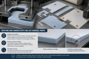
Precision conversion can protect or damage the thermal performance. Aerogel can be crushed at the cut edge, exposed by incomplete encapsulation, contaminated by particles, or distorted during liner removal.
The drawing should define overall profile, active insulation area, installed thickness, vent and terminal keep-outs, edge-seal width, adhesive pattern, liner split, pull tabs, cutout radii, locating features, flatness, cleanliness, and packaging orientation.
Tool clearance, blade condition, cutting pressure, support liner, web tension, dust extraction, part handling, and inspection should be validated for the chosen laminate. Prototype tooling should allow quick revision after thermal and assembly tests.
A lower-conductivity grade that produces poor edges, high scrap, or dimensional instability may cost more and perform less consistently than a stronger reinforced grade.
Industry Insight: Thermal Resistance Is Replacing the Headline k-Value
EV battery teams are increasingly asking for installed thermal resistance, compression-dependent data, time-to-temperature curves, and module propagation evidence rather than one room-temperature conductivity number.
This shift is driven by high-integration packs, large-format cells, fast charging, and stricter thermal-propagation expectations. Thin materials must provide thermal, mechanical, dielectric, cleanliness, and automated-assembly functions simultaneously.
Aerogel development is moving toward reinforced and multifunctional composites with radiation-control additives, high-temperature facings, pressure-management layers, dielectric skins, and phase-change or heat-spreading features.
For a die-cut converter, the commercial opportunity is to sell a validated functional part, not only a square meter of insulation. DFM, laminate control, rapid prototypes, APQP, PPAP, and traceability become part of the thermal-performance value proposition.
RFQ Checklist for EV Aerogel Insulation Thermal Conductivity
Provide the cell chemistry, format, capacity, dimensions, SOC, vent location, module layout, electrical connection, cooling method, available gap, free and installed thickness, compression range, and end-of-life swelling allowance.
Define the thermal target: screening conductivity, test method and temperature, cold-side temperature threshold, required propagation delay, no-propagation observation period, heat-flux or flame exposure, and module test method.
Send the CAD or PDF drawing with critical dimensions, tolerances, adhesive zones, edge seals, liner split, pull tabs, material restrictions, dielectric and flame requirements, cleanliness, packaging, annual volume, and PPAP needs.
Request data for the exact finished laminate, including thermal, compression, high-temperature, dielectric, flame, aging, adhesive, chemical, lot-traceability, inspection, and change-control evidence.
How Boost Insulation Supports EV Aerogel Barrier Projects
Boost Insulation supports EV and energy-storage programs with aerogel, flame-retardant polycarbonate, silicone foam, mica, dielectric films, pressure-sensitive adhesives, precision lamination, slitting, and custom die cutting.
The company states that it provides DFM support, cleanroom conversion, tolerance capability down to plus or minus 0.05 mm for suitable parts, 48-hour rapid prototyping, APQP and PPAP support, and lot traceability.
Engineering support can include material screening, conductivity-data review, installed-thickness analysis, compression planning, vent keep-outs, adhesive zoning, edge encapsulation, liner and pull-tab design, prototype production, dimensional inspection, and test-sample preparation.
For a useful quotation, upload the cell or module drawing and provide the measurement method, conductivity target, installed thickness, compression range, vent direction, safety criterion, material restrictions, validation plan, annual volume, and current assembly or test concern.
| Need a conductivity review and production-ready aerogel barrier?
Send Boost Insulation your cell or module drawing, conductivity test requirement, installed thickness, compression range, vent direction, safety criterion, dielectric and flame requirements, validation plan, and annual volume. The engineering team can review aerogel, PC insulation, silicone foam, mica, films, adhesives, and precision die-cut options. Visit boostinsulation.com to upload a drawing or request a quote |
Frequently Asked Questions
Is 0.020 W/mK a good aerogel conductivity for EV batteries?
Yes, it is a strong screening value for many reinforced battery-grade aerogel composites when measured under defined room-temperature conditions. The finished part must still be evaluated at installed thickness, compression, elevated temperature, and module level.
Should EV aerogel insulation be below 0.025 W/mK?
A maximum near 0.025 W/mK is a reasonable commercial screening target for many cell-to-cell barriers. It is not a universal pass/fail limit; thickness, mechanical stability, and system testing can justify a different value.
Is 0.015 W/mK always better than 0.022 W/mK?
Not necessarily. The 0.015 result may come from a fragile laboratory specimen or different test conditions. Compare the same method, temperature, thickness, direction, compression, and finished laminate.
Does aerogel conductivity increase with temperature?
The effective heat-transfer behavior can increase as temperature rises, particularly because radiation becomes more important. Request elevated-temperature data or cold-side temperature curves for the finished construction.
How does compression affect aerogel conductivity?
Compression can increase solid contact and reduce thickness, lowering total thermal resistance. Controlled pressure may improve assembly, but the material must be tested across the production compression window.
Should the conductivity test include the adhesive and film?
For final selection, yes. Bare-core data is useful for screening, but the production laminate with film, adhesive, reinforcement, and edge construction is more representative.
What test standard should be used?
ASTM C518 or ISO 8301 heat-flow-meter methods are common for flat insulation specimens. The report should state all test conditions. Other agreed methods may be used for special thicknesses or temperatures.
Can low thermal conductivity prove no thermal propagation?
No. Propagation also depends on cell energy, vents, radiation, flame, metal heat bridges, cooling structures, electrical connection, and geometry. Module and pack testing are required.
Technical References
- ASTM International. ASTM C518-21, Standard Test Method for Steady-State Thermal Transmission Properties by Means of the Heat Flow Meter Apparatus. Source
- International Organization for Standardization. ISO 8301:1991, Thermal insulation – Determination of steady-state thermal resistance and related properties – Heat flow meter apparatus; confirmed current in 2025. Source
- United Nations Economic Commission for Europe. UN Regulation No. 100, Revision 3, Rechargeable Electrical Energy Storage System requirements. Source
- Liu, Q. et al. “Influence of Aerogel Felt with Different Thickness on Thermal Runaway Propagation of 18650 Lithium-ion Battery.” Electrochemistry, 2022. Source
- Hou, X. et al. “Thermal Insulation and Fireproof Aerogel Composites for Automotive Batteries.” Gels, 2025. Source
- Wang, A. et al. “Research Progress of Aerogel Used in Lithium-Ion Power Batteries.” Journal of Materials Research and Technology, 2024. Source
- UL Solutions. Combustion (Fire) Tests for Plastics: UL 94 V and VTM test classifications and limitations. Source
- Boost Insulation. EV battery insulation, aerogel, flame-retardant polycarbonate, thermal management, precision die cutting, rapid prototyping, APQP, and PPAP capabilities. Source
Related Posts:
How Much Delay Can an Aerogel Barrier Provide in EV Packs?
How Is Aerogel Used Between Prismatic EV Battery Cells?
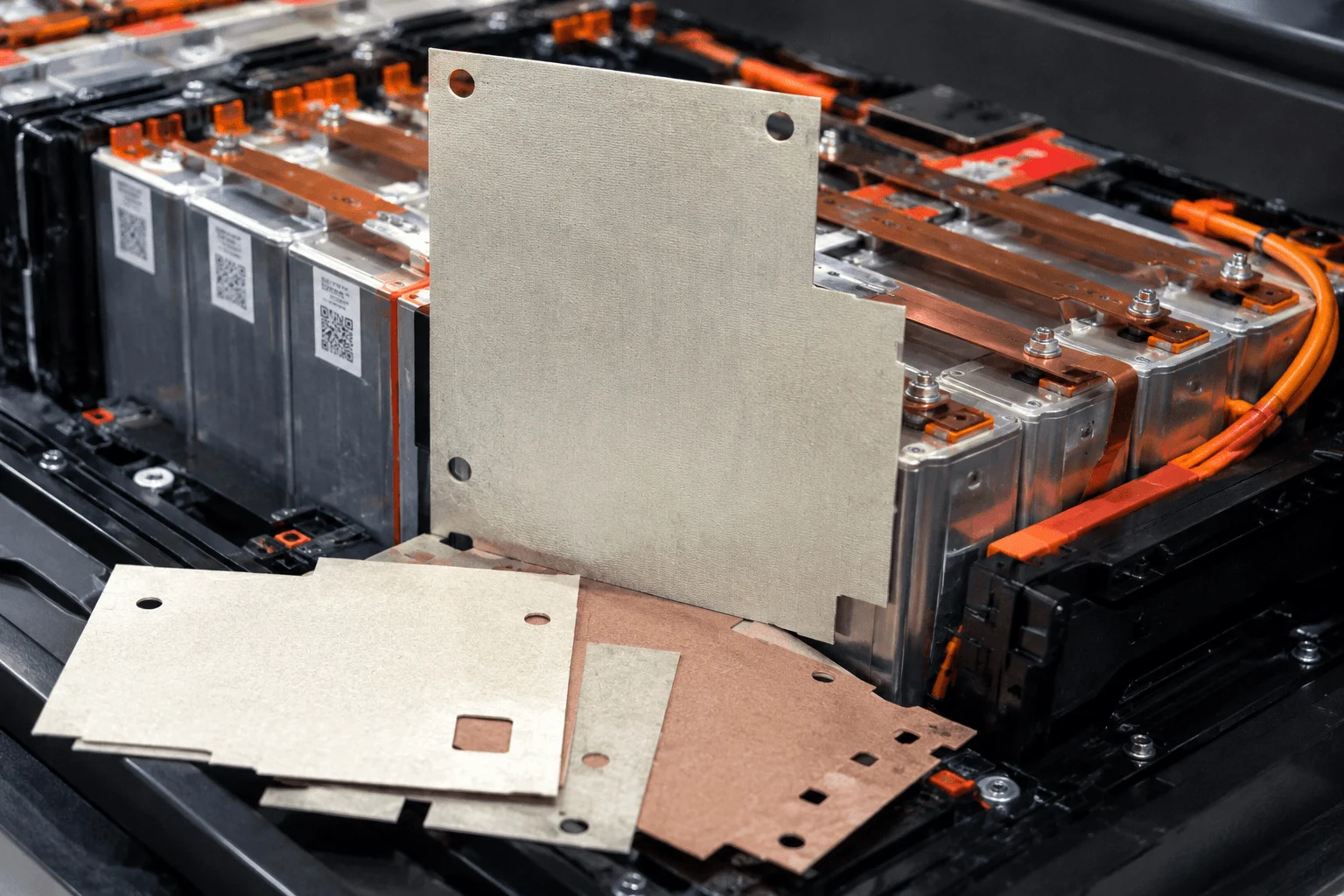
What Is a Mica Insulation Sheet for EV Battery Packs?
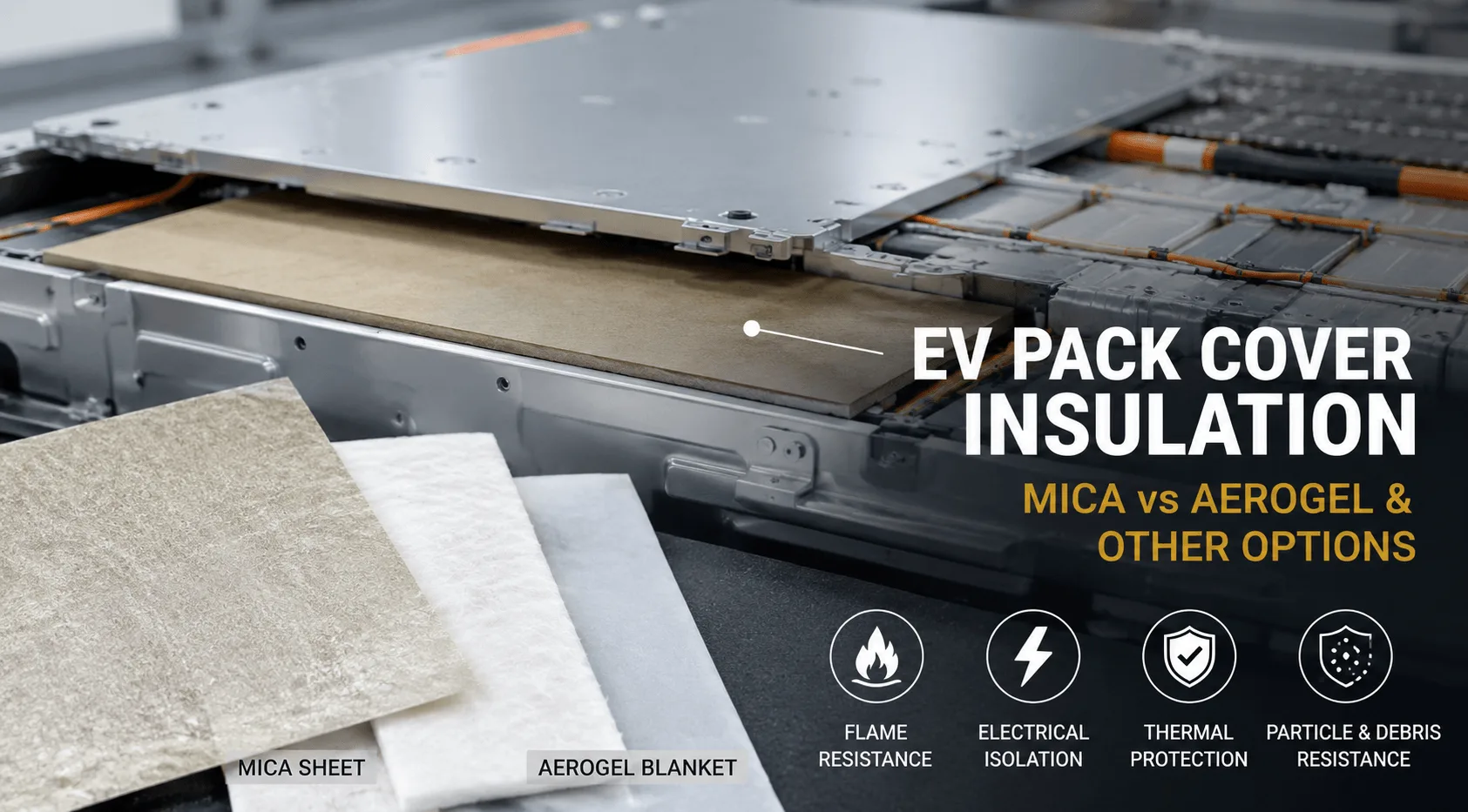
Which Insulation Material Is Best Under EV Pack Covers?

What Is ESS Energy Storage Solution & How It Works?
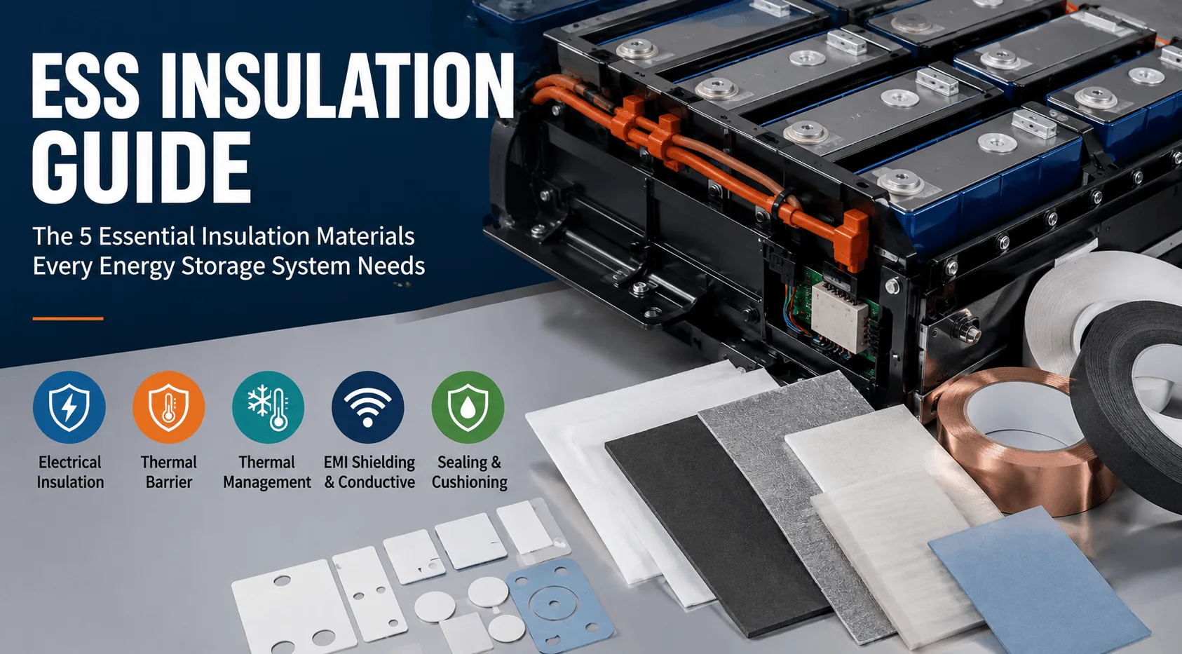
What Insulation Does an Energy Storage System Need?
 betty wong