How Does a Mica Insulation Sheet Protect EV Batteries?
Table of Contents
What protects an EV battery when a nearby cell vents flame, a busbar shifts toward the enclosure, or a polymer insulation film begins to soften under extreme heat? A mica part may be less visible than the cooling plate or battery-management system, yet its location and construction can determine whether heat, voltage, and flame remain contained—or find a fast path into the next module.
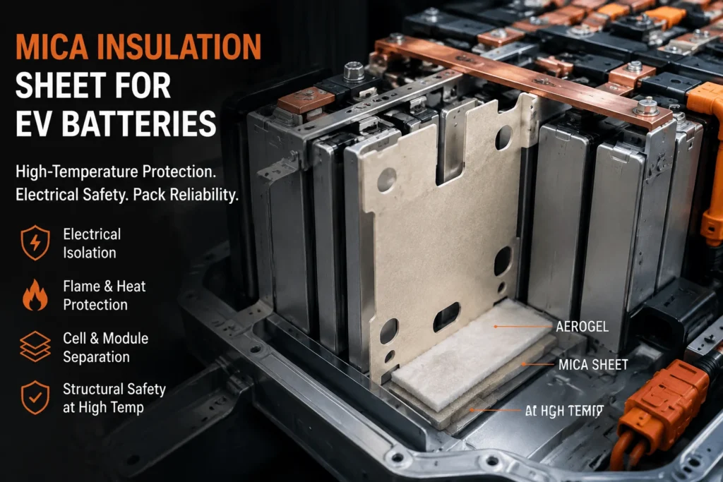
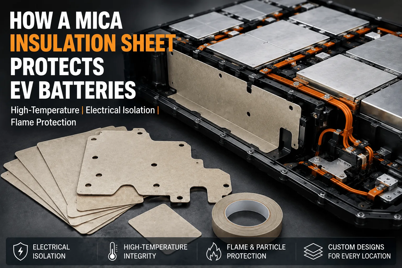
| A mica insulation sheet protects EV batteries by combining high-temperature structural integrity with electrical isolation and flame resistance. It separates high-voltage conductors from metal structures, shields cells and pack covers from hot gas, flame, and particles, and forms module or enclosure barriers that remain in place after many polymer films soften. Mica does not replace cooling, vent routing, aerogel, or pack-level testing; it works as one layer in a validated thermal-runaway and dielectric protection system. |
Mica Insulation Sheet for EV Batteries: Protection at a Glance
| Protection Function | Typical Location | Mica Contribution | Required Validation |
| High-voltage isolation | Busbars, connectors, frames, junction boxes | Dielectric barrier and creepage support | Withstand voltage, aging, edge inspection |
| Thermal-runaway flame protection | Cell vents, module walls, pack cover | High-temperature barrier against flame and particles | Impingement and module/pack testing |
| Cell or module separation | Cell faces, sidewalls, module partitions | Physical and electrical boundary | Compression, thermal propagation, vibration |
| Structural fire protection | Pack lid, perimeter, service zones | Maintains barrier integrity after polymer softening | Burn-through, mounting, enclosure test |
How a Mica Insulation Sheet for EV Batteries Protects the Pack
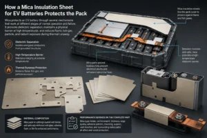
Mica protects an EV battery through several mechanisms that work at different stages of normal operation and failure. During everyday service, it provides dielectric separation between energized conductors and grounded structures. During abnormal heating, it maintains a physical barrier at temperatures that can soften or destroy many polymeric films. During thermal runaway, it can reduce direct flame, hot-gas, particle, and radiant exposure to adjacent cells, module walls, busbars, wiring, and the pack lid.
The material is effective because mica consists of layered silicate minerals with strong electrical-insulation characteristics and high thermal stability. Commercial battery parts are usually engineered laminates made from mica paper or mica splitting’s combined with a binder and, when needed, glass reinforcement, adhesive, foam, film, or another protective layer.
The protective result depends on the complete converted part. Mica type, binder, reinforcement, thickness, edge quality, adhesive pattern, mounting, support, vent direction, and surrounding metal paths all affect performance. A sheet that works well as a flat coupon can crack around a hole, delaminate near a hot edge, or be bypassed by an exposed busbar in the real pack.
Why a Mica Insulation Sheet for EV Batteries Is More Than a Thermal Pad
A common specification error is to group mica with every other ‘thermal pad’. Mica is not normally selected to conduct routine cell heat into a cold plate, and it does not offer the same low through-thickness thermal conductivity as aerogel. Its main value is maintaining dielectric and flame-barrier functions under severe temperature.
Normal thermal-management materials—thermal interface pads, gels, and gap fillers—move heat toward the cooling system. Mica generally resists or redirects abnormal heat and keeps conductive components separated. Placing mica across an intended cooling path without thermal analysis can increase cell temperature and accelerate aging.
The pack therefore uses different materials for different directions of heat flow. Conductive pads move normal operating heat toward coolant. Aerogel can create high thermal resistance between cells. Silicone foam can manage swelling and vibration. Mica provides high-temperature dielectric and fire protection where physical integrity must be retained.
How a Mica Insulation Sheet for EV Batteries Prevents Electrical Shorts
EV packs contain series-connected cells, busbars, fuse elements, contactors, service disconnects, sensing circuits, and grounded enclosure structures in a compact space. A mica sheet can provide a solid insulating barrier between these parts and reduce the risk of an internal short caused by movement, burrs, debris, vibration, or deformation.
Typical locations include beneath busbars, between high-voltage conductors and module frames, around contactor or fuse assemblies, inside junction boxes, and between cells or modules and the metal enclosure. A die-cut mica profile can include extensions, slots, folds, and local shields that increase the surface path between conductors.
Electrical protection must be specified with measurable criteria. Define dielectric strength, insulation resistance, test voltage, dwell time, leakage-current limit, minimum thickness, humidity conditioning, temperature, and post-aging requirements. A generic claim such as ‘high dielectric strength’ is insufficient for a production drawing.
Edges deserve special attention. A cracked cutout, sharp metal corner, adhesive contamination, exposed fastener, or narrow web can reduce the effective insulation path even when the center of the sheet passes a dielectric test. Creepage and clearance are properties of the complete geometry, not only the raw material.
How a Mica Insulation Sheet for EV Batteries Survives High Heat
Many polymer films provide excellent electrical insulation during normal operation but soften, shrink, melt, carbonize, or lose mechanical strength under severe battery-failure temperatures. Mica-based sheets are selected because the mineral phase can retain a physical barrier under much higher heat.
The practical performance is controlled by more than the mica mineral. The binder may decompose before the mica itself, causing a laminate to become brittle or delaminate. Glass fabric can improve mechanical support. A silicone binder may provide better high-temperature flexibility than a lower-temperature resin, while a rigid epoxy system may offer stronger room-temperature structure.
Ask suppliers to separate continuous service temperature, short-term exposure temperature, and direct-flame performance. A sheet that tolerates a brief peak temperature is not necessarily suitable for continuous operation at that temperature. Post-exposure integrity, shrinkage, cracking, mass loss, and dielectric retention are more useful than one maximum-temperature number.
For critical barriers, test the finished laminate at the specified minimum thickness. Adhesive, film, printing, reinforcement, and edge treatment can fail before the mica core.
How a Mica Insulation Sheet Protects EV Batteries From Flame and Ejecta
Thermal runaway can release hot gas, flame, electrolyte droplets, and solid particles. These hazards can erode thin polymer layers, ignite nearby components, contaminate high-voltage surfaces, or heat the adjacent cell faster than conduction through the cell wall alone.
Mica can form a flame-facing surface that resists direct exposure and protects the material or component behind it. It is used at pack lids, module boundaries, vent corridors, perimeter walls, and around high-voltage hardware. Rigid or supported mica can also provide a shield against particle impact.
The sheet should not be positioned to block a cell pressure-relief vent. It should protect the receiving surface while the pack provides a controlled path for gas and particles. Blocking the vent can increase pressure or redirect the event into another cell.
A severe direct jet may require a thicker mica grade, a reinforced construction, a shaped deflector, or a mica-plus-aerogel stack. Application-level flame and vent testing is required because small-scale material flame ratings do not reproduce battery ejecta.
Where a Mica Insulation Sheet for EV Batteries Is Installed
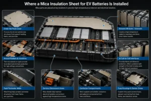
Under the pack cover, mica can protect the lid and vehicle-side structures from upward venting, flame, and particles. The part may be a large rigid panel, a flexible liner, or a shaped composite around ribs and fasteners.
Between modules or along module sidewalls, mica can create a high-temperature dielectric boundary. This placement can limit direct flame transfer and protect module frames, wiring channels, cooling components, or neighboring modules.
Around busbars and high-voltage junctions, thin mica sheets or tapes provide local electrical and heat protection. Flexible tape can wrap irregular conductors, while rigid die-cut parts can cover broad metal surfaces and maintain controlled clearances.
At cell-to-cell interfaces, mica may be used when the primary requirement is flame and dielectric protection. When the design also needs very high thermal resistance in a thin gap, mica is often combined with aerogel or a compliant thermal-runaway pad.
Pack perimeter walls, service-disconnect areas, contactor compartments, fuse housings, and sensor zones may also use custom mica parts. The best placement follows the actual heat, voltage, and vent paths identified in the module or pack design.
How a Mica Insulation Sheet Protects Prismatic EV Cells
Prismatic cells present large flat faces and often use top pressure-relief vents. A mica barrier may protect module sidewalls, end plates, terminal zones, or the broad interface between cells. Near-full coverage can reduce flame and radiant exposure, but the design must preserve the vent opening and intended cooling contact.
The upper edge is frequently the most sensitive area. A broad-face mica part that stops too low can leave the cell shoulder or busbar exposed. A part that extends over the vent can interfere with pressure relief. A stepped profile or separate top shield is usually safer than one undifferentiated sheet.
Prismatic cells swell over life, so rigid mica must be supported or combined with a compliant layer. Silicone foam can absorb dimensional change, while mica supplies the fire and dielectric surface. The compression system should prevent cracking and maintain uniform cell pressure.
Cooling plates and side frames can conduct heat around the mica. Instrument the metal paths during module tests rather than assuming the broad-face barrier controls the complete event.
How a Mica Insulation Sheet Protects Pouch EV Cells
Pouch cells require smooth, uniform support because the laminate enclosure is mechanically sensitive. A mica part placed between pouch cells should avoid hard local steps, rough edges, thick adhesive overlaps, or protruding pull tabs that concentrate pressure.
Flexible mica paper or a thin reinforced mica laminate can provide flame and dielectric protection. A separate silicone foam layer may manage swelling and stack preload. The layer sequence should be tested so that the foam does not bend or crack the mica during cycling.
The profile should avoid pouch seals, tabs, and gas pockets. The active electrode area, outside pouch dimension, and swelling envelope are not identical, so the cell manufacturer’s detailed drawing is required.
Because venting from a pouch failure may be less geometrically predictable than from a rigid safety vent, broader top or side shielding may be required. Test aged and swollen assemblies, not only new flat coupons.
How a Mica Insulation Sheet Protects Cylindrical EV Cells
Cylindrical modules often use mica as row partitions, group barriers, perimeter liners, top shields, sleeves, or local busbar insulation. A small flat piece at the tangent contact between two cans may not control hot gas flowing through the open channels between cells.
Axially venting cells can expose the top cover and busbar system. An under-lid mica barrier or vent manifold can be more important than a barrier at the cylinder contact point. Sidewall rupture requires additional radial protection.
The mica construction must retain shape around cell holders and cooling passages. A mechanically reinforced grade is often preferable to unsupported brittle sheet. Edges and cutouts should not interfere with airflow, liquid-cooling structures, or exhaust channels.
Representative module testing or flow simulation can identify whether row barriers, cell-group partitions, or perimeter shields provide the greatest protection.
How a Mica Insulation Sheet for EV Batteries Protects the Pack Lid
The pack cover is often exposed to the combined plume from one or more venting cells. Protecting the lid can reduce burn-through, maintain separation from the vehicle floor or cabin, and protect wiring or structural adhesives above the cell array.
A lid liner must cover the predicted flame and hot-gas footprint, including areas where the plume strikes the cover and spreads laterally. Ribs, bolts, gaps, seal flanges, and openings can become bypass paths.
Rigid mica board offers stable coverage on flat lids. Flexible or segmented mica can follow stamped surfaces. Adhesive-backed constructions simplify assembly, but the adhesive must survive production conditions and support the part long enough during the event.
The mica should be tested with the actual lid material, support spacing, attachment method, vent distance, and representative flame or cell event. A sheet tested on a solid laboratory plate may behave differently across an unsupported panel span.
How a Mica Insulation Sheet for EV Batteries Protects Busbars
Busbars carry high current and connect cells or modules at different potentials. Mica can isolate the conductor from module frames, lids, cooling parts, and neighboring conductors while providing a high-temperature surface around the electrical connection.
A die-cut busbar insulator may include holes, slots, folds, terminal windows, and locating features. These details must maintain electrical clearance and avoid cracking during installation.
Flexible mica tape is useful for wrapping complex shapes or covering a conductor edge. Rigid mica-polymer laminates may provide better puncture resistance and assembly precision. Flame-retardant polycarbonate can be added where a clean structural surface is required.
After aging, vibration, and heat exposure, verify that the mica remains attached and that the dielectric path is not shortened by adhesive flow, metal burrs, fastener movement, or contamination.
Muscovite vs Phlogopite Mica for EV Battery Protection
Muscovite and phlogopite are the two mica types most commonly discussed for engineered insulation. Muscovite is generally associated with strong dielectric properties, while phlogopite is often selected for higher-temperature and chemical-resistance requirements.
The final choice depends on location. A busbar or junction-box part may prioritize dielectric strength, thinness, and punch quality. A vent-facing or under-lid barrier may prioritize heat and flame stability.
Binder, reinforcement, and thickness can outweigh the mineral choice. A phlogopite paper with an unsuitable adhesive may fail earlier than a well-designed muscovite laminate in a moderate exposure zone.
Request test data for the exact construction and thickness. Do not approve a material based solely on the name of the mica mineral.
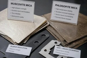
Rigid and Flexible Mica Insulation Sheet Designs
Rigid mica boards are used for flat pack covers, module partitions, sidewalls, end plates, and large high-voltage barriers. They provide stable positioning but can crack if bent over uneven structures or installed with excessive fastener load.
Flexible mica sheets and tapes are useful around curved surfaces, cables, busbars, and complex geometries. Their flexibility comes from the mica-paper structure, binder, reinforcement, and reduced thickness.
Semi-flexible laminates can combine the advantages of both. A polymer or glass carrier can improve handling, while the mica supplies high-temperature dielectric protection.
Select the format from the installation method, minimum bend radius, support spacing, vibration, flame exposure, and die-cut geometry. A single pack may use rigid panels and flexible tape in different locations.
How Thickness Changes Mica Protection in EV Batteries
Increasing mica thickness can improve dielectric margin, flame resistance, burn-through time, stiffness, and resistance to particle erosion. It also adds weight, cost, and package height and may reduce flexibility.
The correct thickness depends on the exact grade, mica type, binder, reinforcement, voltage, unsupported span, vent or flame exposure, and test target. There is no universal EV thickness.
Specify minimum finished thickness, not only a nominal average. Pressing, grinding, laminating, adhesive, and tolerance variation can create thinner local regions.
Holes, edges, folds, and fastener zones may require additional thickness or reinforcement. Qualification samples should represent the minimum allowed production thickness and worst-case geometry.
How Binder and Reinforcement Affect Mica Protection
Mica paper requires a binder and often a reinforcing carrier to become a practical sheet. Silicone binders can provide high-temperature flexibility, while epoxy or other resin systems can create stiffer structural boards.
Higher binder content can improve toughness and die-cut handling but may reduce high-temperature integrity, increase smoke, or change flame behavior. The mica may remain stable after the polymer phase has degraded, but the part can delaminate or lose support.
Glass fabric, glass fiber, polymer film, or other reinforcement can improve tensile strength and puncture resistance. These layers also change thermal conductivity, thickness, dielectric behavior, and cutting response.
The complete bill of materials should be controlled. A supplier change in binder percentage or carrier fabric may require requalification even when the product name remains unchanged.
How Adhesive-Backed Mica Protects EV Batteries
Pressure-sensitive adhesive allows mica parts to be installed quickly and held in place before final module assembly. This is useful on pack lids, busbars, sidewalls, junction boxes, and large liners.
The adhesive must be compatible with aluminum, steel, coated metal, polymer frames, or other substrates and must retain sufficient bond after heat, humidity, vibration, and chemical exposure.
Full-face adhesive maximizes initial contact but adds a continuous polymer layer. Selective adhesive can reduce cost, mass, and thermal bridging while maintaining position.
Define vent, terminal, weld, and high-temperature keep-out zones. Adhesive squeeze-out can contaminate electrical surfaces or create a path around the mica. Liner split, pull tabs, and release force should support error-free production.
How Mica, Aerogel, PC, and Silicone Foam Protect EV Batteries Together
No single material provides every battery-protection function. Mica supplies high-temperature dielectric and flame integrity. Aerogel provides very high thermal resistance in a thin gap. Flame-retardant polycarbonate supplies puncture-resistant structural dielectric coverage. Silicone foam manages swelling, vibration, and tolerance.
A cell-to-cell composite may use aerogel as the central thermal resistor, mica on the hot side for flame protection, and silicone foam in a controlled compression zone. A busbar barrier may combine mica with PC film. A pack lid may use mica with aerogel or silicone fire-protection layers.
Layer order matters. The strongest flame-facing layer should be located toward the expected hot side. The compliant layer should not over compress the aerogel or bend the mica.
Every added layer creates adhesive interfaces, thickness tolerance, cost, and possible heat paths. Use the simplest stack that meets the validated functions.
How Die-Cut Geometry Determines Mica Protection
A mica sheet can pass material tests and still fail because of poor part geometry. Sharp internal corners, narrow webs, unsupported holes, small bend radii, and edge notches concentrate stress and can initiate cracks.
The drawing should define overall dimensions, thickness, tolerance, hole sizes, edge distances, corner radii, adhesive zones, liner split, pull tabs, bend areas, flatness, and edge-quality limits.
Protective coverage must remain continuous around the real heat or electrical path. A large terminal cutout or uncovered corner can become the dominant flame, radiation, or creepage route.
Locating holes and asymmetric features can prevent incorrect installation. However, every hole should be reviewed for dielectric and mechanical risk. Reinforcement or a laminated PC film may be required around critical openings.
Precision Die Cutting a Mica Insulation Sheet for EV Batteries
Mica-based laminates can crack, split, delaminate, fray, or release dust during conversion. The risk depends on the mica grade, binder, reinforcement, thickness, feature design, tool clearance, support liner, and handling.
Flatbed die cutting, rotary die cutting, stamping, CNC cutting, and other processes may be used. Rotary processes support high volume when the laminate and geometry are suitable. Rigid thick boards may require specialized tooling or CNC processing.
ool condition is critical. A dull or poorly supported cut can crush edges or pull layers apart. Dust extraction and clean handling reduce contamination of dielectric surfaces.
Prototype the exact material stack before freezing the module drawing. A part that cuts cleanly without adhesive may behave differently after film and liner lamination.
How a Mica Insulation Sheet for EV Batteries Is Validated
Level 1 verifies raw material and laminate properties: thickness, density or areal mass, dielectric strength, insulation resistance, flexural or tensile strength, binder content, high-temperature shrinkage, flame response, moisture, and chemical compatibility.
Level 2 verifies the converted part: dimensional accuracy, edge cracks, delamination, puncture, bend performance, adhesive peel, liner release, cleanliness, and packaging.
Level 3 uses heat-flux, burner, hot-gas, or impingement coupon testing to compare cold-side temperature, flame exposure, erosion, edge penetration, and post-test integrity.
Level 4 uses representative module thermal-propagation testing with the real cell, state of charge, electrical connections, vents, busbars, cooling system, compression, and enclosure geometry.
Level 5 confirms pack or vehicle performance, including warning, venting, external hazards, electrical isolation, structural integrity, and post-event safety. Material data cannot replace this system-level validation.
Common Mica Protection Mistakes in EV Battery Packs
The first mistake is treating mica as a universal low-conductivity material. If the main objective is delaying conductive heat across a thin cell gap, aerogel or a composite may be necessary.
The second mistake is blocking a pressure-relief vent with a flat mica part. The design should shield receiving surfaces while preserving controlled exhaust.
The third mistake is relying on the raw sheet while ignoring adhesive, holes, edges, unsupported spans, and metal heat bridges. The complete part and surrounding geometry determine protection.
The fourth mistake is quoting UL 94 V-0 as proof of thermal-runaway protection. UL 94 is a small-scale flammability classification for the rated material and thickness; it does not establish battery jet-flame resistance or pack compliance.
The fifth mistake is changing the mica type, binder, reinforcement, adhesive, thickness, or converter after validation without technical review. Change control must cover the full construction.
Industry Insight: Mica Protection Is Becoming Multifunctional
EV battery programs are moving from simple flat mica boards toward thin die-cut laminates, adhesive-backed shapes, mica-plus-foam compression pads, mica-aerogel barriers, and shaped under-lid components.
The change is driven by higher cell energy, tighter packaging, cell-to-pack designs, fast charging, and stronger expectations for thermal-propagation control. Materials must perform more functions in less space.
Buyers increasingly request application data rather than generic maximum-temperature claims: burn-through time, heat-flux curves, post-flame dielectric integrity, compression behavior, edge durability, vent-impingement results, and module tests.
This shift favors converters that can support DFM, multilayer lamination, tight die-cut tolerances, clean processing, rapid prototypes, APQP, PPAP, traceability, and disciplined engineering changes.
How to Specify a Mica Insulation Sheet for EV Batteries
Specify the mica type, natural or reconstituted construction, binder, reinforcement, thickness and tolerance, density or areal mass, rigid or flexible format, dielectric strength, insulation resistance, temperature exposure, flame classification, and approved supplier.
Define the exact application: cell interface, module wall, busbar, junction box, perimeter, lid, or vent corridor. Identify the protected surface and expected heat, flame, voltage, and mechanical loads.
The drawing should include vent and terminal keep-outs, holes, radii, minimum webs, bends, adhesive zones, liner split, pull tabs, edge requirements, orientation, labeling, and packaging.
Add validation criteria, sampling plans, certificate requirements, lot traceability, PPAP level, and change-control conditions. The specification should cover the finished die-cut part rather than only the raw mica sheet.
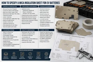
RFQ Checklist for a Mica Insulation Sheet for EV Batteries
Send the pack voltage, cell format, module layout, protected component, vent location, expected flame or heat exposure, available thickness, electrical-clearance requirement, substrate, mounting method, and annual volume.
Provide a PDF or CAD drawing with dimensions, tolerances, holes, bends, adhesive pattern, liner split, pull tabs, orientation, and packaging requirements.
State the required mica type or performance target, binder restrictions, dielectric voltage, temperature exposure, flame requirement, environmental aging, and material-compliance documentation.
Include prototype quantity, validation schedule, PPAP requirements, target production timing, and any current cracking, delamination, bonding, or thermal-test problem.
How Boost Insulation Supports Mica EV Battery Protection
Boost Insulation positions itself as a China-based EV insulation and precision die-cut manufacturer with IATF 16949 and ISO 9001 quality systems. Its public site describes DFM support, in-house tooling, cleanroom lamination and die cutting, APQP and PPAP support, and lot traceability.
The company also promotes rapid custom samples, tight dimensional control for suitable parts, and a material portfolio that includes mica, flame-retardant polycarbonate, aerogel, silicone sheets, thermal pads, films, and adhesives.
For a mica project, engineering support can include grade selection, rigid or flexible construction, adhesive pattern, mica-plus-foam or mica-plus-PC lamination, edge reinforcement, die-cut geometry, prototype tooling, dimensional inspection, voltage testing, aging tests, and production packaging.
To receive a useful DFM response, upload the cell, module, busbar, pack-cover, or enclosure drawing together with voltage, temperature, flame exposure, target thickness, assembly method, annual volume, and validation plan.
| Need a mica fire barrier, busbar insulator, or pack-lid component?
Send Boost Insulation your module, busbar, pack-cover, or enclosure drawing together with the voltage, temperature, flame exposure, target thickness, adhesive needs, test plan, annual volume, and PPAP requirements. The engineering team can review mica, flame-retardant PC, silicone foam, aerogel, films, adhesives, and precision die-cut options. Visit boostinsulation.com to upload a drawing or request a quote |
Frequently Asked Questions
Can mica stop thermal runaway in an EV battery?
Mica can delay heat and flame transfer and help maintain a physical and dielectric barrier, but it cannot independently guarantee non-propagation. Cell energy, thickness, vent routing, metal heat paths, cooling, and pack geometry must be validated.
Is mica better than aerogel between battery cells?
Mica is generally stronger for direct flame, high-temperature structural integrity, and electrical insulation. Aerogel generally offers lower thermal conductivity. Many high-performance barriers combine both.
Can mica be used as a busbar insulator?
Yes. Thin sheets and mica tapes can isolate busbars and high-voltage components, provided dielectric strength, creepage, edges, adhesive, vibration, and aging are validated.
Does a mica insulation sheet need UL 94 V-0?
Project requirements vary. Some finished mica laminates carry UL 94 classifications. Verify the exact grade and thickness, and do not treat the rating as proof of battery thermal-runaway performance.
Can mica insulation be adhesive-backed?
Yes. Pressure-sensitive adhesive can simplify assembly. The adhesive must be compatible with the substrate, temperature, humidity, vibration, and flame exposure.
How thick should mica be in an EV pack?
There is no universal thickness. Select it from the dielectric voltage, flame or heat load, unsupported span, stiffness, package space, and representative test result.
Can mica be combined with silicone foam?
Yes. Silicone foam can manage cell swelling and tolerance, while mica provides a flame and dielectric surface. The complete stack must be tested under installed compression.
What files are needed for a custom die-cut mica part?
Provide a PDF or CAD drawing, thickness, voltage, temperature and flame requirements, adhesive zones, tolerances, annual volume, packaging, and validation plan.
Technical References
- Boost Insulation. EV battery insulation, precision die cutting, DFM, rapid prototyping, APQP, PPAP, and traceability capabilities. Source
- United Nations Economic Commission for Europe. UN Regulation No. 100, Revision 3, rechargeable electrical energy storage system and thermal-propagation requirements. Source
- Saint-Gobain Tape Solutions. Breaking Free from Mica in Car Battery Insulation, 2024. Source
- Saint-Gobain Tape Solutions. Thermal Runaway Protection Solutions Enhance EV Safety, 2025. Source
- Electrolock. Thermal Runaway Protection in EV Batteries: The Role of Mica. Source
- UL Solutions. ANSI/UL 94 small-scale flammability data and limitations for plastic materials. Source
- Kim, H. S. et al. Flame-Retardant Battery Pack Case Design for Delaying Thermal Runaway. Materials, 2025. Source
- Bai, Q. et al. Influence of Insulation Material Thickness on Spread of Thermal Runaway in Battery Packs. Processes, 2023. Source
Related Posts:
What Thermal Conductivity Should EV Aerogel Insulation Have?
How Does Aerogel Slow Cell-to-Cell Heat Transfer in EVs?
Why Do EV Battery Packs Use a Mica Insulation Sheet?
Can Aerogel Stop Thermal Runaway Propagation in EV Packs?
How Much Delay Can an Aerogel Barrier Provide in EV Packs?
Is Flame Retardant Polycarbonate Better Than Acrylic?
 betty wong