
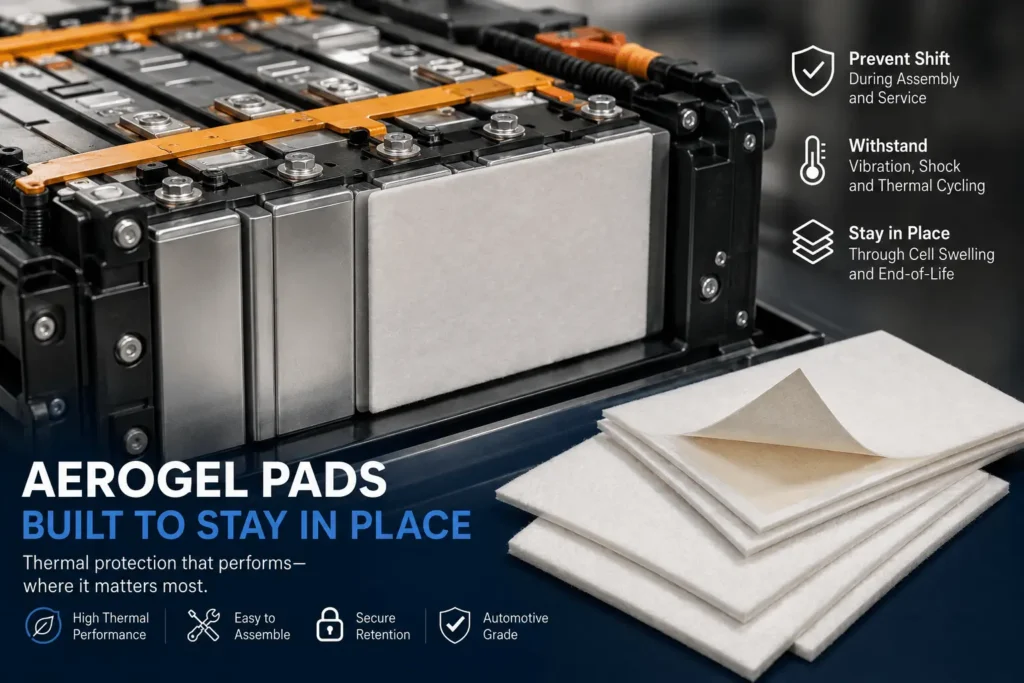
How Do You Prevent Aerogel Pads From Shifting in EV Packs?
An aerogel pad can pass a thermal test on the bench and still become a weak point in the vehicle if it moves a few millimeters during cell stacking, pack transport, vibration, or years of cell swelling. If the pad slides away from the intended hot-face area, exposes an edge, folds, or rides up toward a busbar or vent path, the pack no longer has the barrier geometry the thermal design assumed. So the real engineering question is not simply whether aerogel insulates well. It is whether the aerogel part stays exactly where it must be throughout assembly and service.
To prevent aerogel pads from shifting in EV packs, use a retention system rather than relying on friction alone: stabilize the aerogel with an encapsulation or carrier layer, add a battery-compatible pressure-sensitive adhesive (PSA) where appropriate, design tabs, slots, shoulders, or frame features for positive location, and use controlled module stack compression to hold the finished assembly. For automotive programs, a hybrid approach—light adhesive for assembly positioning plus mechanical location and final stack preload—is usually the most robust. Validate the design after vibration, shock, thermal cycling, compression aging, and end-of-life cell swelling.
Engineering takeaway: The best retention design separates temporary assembly fixation from long-term in-pack retention. A thin PSA can stop movement during stacking, while geometry and module preload provide the durable restraint after the pack is clamped.
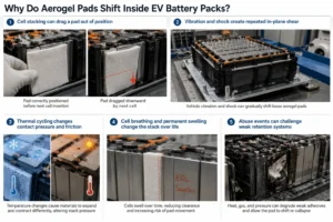
Why Do Aerogel Pads Shift Inside EV Battery Packs?
Aerogel barriers are intentionally thin, lightweight, and thermally resistive. Those same characteristics can make a loose cut pad difficult to handle on a production line. A large, low-mass sheet has little inertia, may have a low-friction film surface, and can be dragged by a neighboring cell or fixture during insertion. If the part is unencapsulated, edge fibers or aerogel dust can also make handling less predictable. Modern automotive aerogel products therefore increasingly appear as engineered, converted parts rather than bare blanket rectangles.
1. Cell stacking can drag a pad out of position
In a prismatic-cell module, the barrier is often placed against a broad cell face before the next cell is added. If the next cell enters with lateral force, catches a pad corner, or is inserted at a slight angle, it can shear the pad downward or sideways. This is especially likely when the design has almost no clearance around the pad perimeter. A part that is dimensionally correct in CAD can still be hard to assemble if its edge is exposed to the cell insertion path.
2. Vibration and shock create repeated in-plane shear
Once the pack is in the vehicle, the barrier sees the same structural environment as the module: road vibration, impact inputs, chassis torsion, temperature changes, and repeated charge-discharge cycles. Major aerogel thermal-barrier suppliers explicitly design battery barriers to withstand vibration and shock and to remain resilient under compression fatigue, which is a useful reminder that thermal resistance alone is not a complete qualification metric.
3. Thermal cycling changes contact pressure and friction
Cells, frames, end plates, carriers, adhesives, films, and insulation layers do not expand at identical rates. As the module moves from cold soak to high operating temperature and back, stack pressure can redistribute. A pad that was held tightly during room-temperature assembly can experience lower local pressure in another state. If the only retention mechanism is static friction, a temporary reduction in normal force can make lateral movement easier.
4. Cell breathing and permanent swelling change the stack over life
Prismatic and pouch cells change thickness as state of charge changes and generally develop some permanent dimensional growth over service life. Compression pads and intercell structures are therefore designed around both cyclical breathing and gradual swelling. An aerogel barrier must remain positioned while this stack geometry evolves. The goal is not to eliminate cell movement; it is to ensure the insulation moves with the intended interface rather than migrating relative to it.
5. Abuse events can challenge weak retention systems
During a severe thermal event, local temperature, gas flow, pressure, and deformation can rise quickly. An adhesive that worked perfectly for normal assembly may soften, decompose, or lose bond strength in an abuse condition. That does not make adhesive-backed aerogel a bad design; it means the adhesive should usually be treated as one layer of the retention architecture, not the only safety-critical restraint. The physical barrier should still be supported by the surrounding stack, carrier, frame, or other geometry.
What Are the Best Ways to Keep Aerogel Pads in Position?
There are five practical retention methods used alone or in combination. The correct choice depends on cell format, module architecture, assembly sequence, available compression, repair strategy, and the temperature envelope the pad must survive.
| Retention method | Main purpose | Strengths | Watch-outs |
| Single-side PSA / transfer adhesive | Hold the pad during cell or module assembly | Fast, automation-friendly, minimal geometry change | Adhesive aging, surface preparation, added layer stack-up, rework |
| Encapsulation / carrier film | Stabilize the aerogel and improve handling | Cleaner handling, better edge integrity, easier die-cutting and picking | Adds film thickness; sealing and film choice must be validated |
| Mechanical locating features | Create positive X-Y location | Very robust, does not depend on bond strength | Needs design space and coordinated cell/frame geometry |
| Controlled stack compression | Hold barriers after clamping | No exposed adhesive required; uses existing module architecture | Requires a verified preload window over life |
| Hybrid retention | Combine assembly aid + long-term restraint | Best tolerance to process variation and life-cycle effects | More DFM work and slightly more part complexity |
1. Use PSA as an Assembly Aid—Not Automatically as the Sole Safety Mechanism
A pressure-sensitive adhesive is one of the simplest ways to stop an aerogel pad from sliding before the module is clamped. Battery thermal-barrier designs and patents describe thermal sheets with PSA or hot-melt adhesive on one or both surfaces, often protected by a release liner for assembly. In practice, the highest-value use of PSA is frequently temporary positioning: it keeps the barrier aligned while operators or automation build the cell stack, then final pack compression takes over much of the mechanical retention.
Select the adhesive from the complete battery environment
Do not select the tape only by room-temperature peel strength. The adhesive system should be screened against the actual cell-can coating or polymer surface, temperature range, humidity, electrolyte exposure risk, dielectric requirement, flame behavior, thickness tolerance, outgassing expectations, and desired reworkability. A high-peel adhesive can still be the wrong choice if it creeps under heat, attacks a coating, adds excessive stiffness, or becomes impossible to remove during service.
Use only as much adhesive area as the retention job needs
Full-surface lamination can improve handling, but it is not always necessary. Depending on the thermal model and assembly process, localized strips, perimeter zones, or small adhesive islands may provide enough anti-slip force while reducing material use and avoiding unnecessary changes to the compressive interface. This must be validated with the real thermal stack; the correct pattern is application-specific.
Design the release liner for the assembly station
A liner that is easy to remove in the sample room may be awkward on a high-volume line. Consider split liners, extended pull tabs, staged liner removal, or kiss-cut liner geometry so the operator or robot can expose adhesive without touching the functional surface. The most successful converted part is not merely the right outer shape—it is delivered in a format that matches the customer’s placement method, take time, and error-proofing strategy.
2. Encapsulate the Aerogel or Laminate It to a Stable Carrier
Encapsulation is one of the most effective ways to improve both handling and dimensional stability. Commercial EV battery solutions are available as encapsulated aerogel pads, and converted aerogel suppliers commonly combine aerogel with protective films or other layers. A film envelope or laminated carrier can reduce dust release, protect fragile edges, improve pick-and-place behavior, and create a more repeatable surface for adhesive application.
For a die-cut converter, encapsulation also changes what is possible geometrically. A stable outer layer can carry registration holes, tabs, pull features, barcodes, printed orientation marks, or adhesive zones that would be difficult to implement on a fragile bare aerogel blanket. This is an important manufacturing insight: the carrier layer may add little thermal resistance, but it can add substantial process capability.
Control the edge construction
The perimeter of the part is often where real packs fail to match the idealized thermal model. An open, ragged edge can shed particles, catch on a neighboring component, or expose the aerogel core. A fully encapsulated edge can be cleaner and stronger, but the sealing method, overlap, and local thickness must not create an unintended hard step that concentrates cell pressure. The edge should be treated as an engineered feature, not leftover trim.
3. Add Positive Mechanical Location: Tabs, Slots, Shoulders, or Frame Capture
Mechanical location is the most direct way to eliminate uncertainty about X-Y position. Battery spacer concepts in the patent literature describe a holding portion around the heat-resistant barrier specifically to make it easier to fix the barrier in position during module assembly. Other traction-battery designs use fingers, slots, or friction-fit features to integrate thermal barriers with adjacent pack structures.
For flat die-cut aerogel parts, positive location can often be added with very little material. Common options include a small locating ear captured by the module frame, a notch against a datum feature, a top tab that sits under a cover or busbar carrier, a shoulder that cannot pass through a cell gap, or a carrier film that extends beyond the aerogel core and is trapped outside the compressed cell face.
Mechanical features should locate the pad without creating a thermal bridge
A locating feature is useful only if it does not undermine the thermal design. Metal fasteners through the center of a barrier, hard polymer ribs across the hot face, or unnecessary cutouts can create bypass paths around the aerogel. Put locating geometry at edges, neutral zones, or carrier extensions whenever possible, and check the complete 3D heat-flow path—not just the nominal conductivity of the aerogel core.
4. Use Controlled Stack Compression as the Long-Term Retention Mechanism
Battery modules are commonly assembled under compression, and published battery thermal-management concepts explicitly note that assembly pressure can hold stacked thermal sheets in place even when no exposed adhesive is used. This makes stack preload a powerful retention tool: once the module is clamped, normal force creates friction over a large face area and prevents the barrier from wandering.
However, ‘the cells are compressed’ is not a sufficient design statement. The engineering team should define the actual pressure window at beginning of life, nominal state of charge, hot and cold conditions, and end of life. The barrier thickness and compressive response need to fit that window. Too little pressure may permit migration; excessive pressure can permanently densify a soft layer, alter thickness, increase stress on the cell, or change the way the stack accommodates swelling.
Validate aerogel in its compressed condition
Thermal barrier performance should be evaluated at the thickness and compression the part sees in the module. Leading aerogel suppliers specifically call out performance under compression and compression-fatigue resilience as design requirements. That matters because a datasheet value measured on an unconstrained sample does not automatically represent a highly compressed multi-layer part after years of cycling.
5. Use a Hybrid Retention Strategy for Automotive-Grade Robustness
For many prismatic EV modules, the strongest design is deliberately redundant: a small amount of PSA holds the barrier to the cell or carrier during assembly; a tab, edge, or frame provides positive location; and final module compression supplies long-term retention. Each mechanism covers a different failure mode. If adhesive wet-out varies, geometry still locates the part. If stack preload changes temporarily, adhesive and capture reduce sliding. If the adhesive loses strength in a high-temperature abuse event, the surrounding structure still supports the barrier.
Best-practice hierarchy: Use friction only when the preload window is proven. Use PSA when assembly movement is the main risk. Use mechanical capture when position is safety-critical. Use a hybrid when the pack must tolerate manufacturing variation, vehicle vibration, and end-of-life swelling with margin.
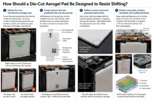
How Should a Die-Cut Aerogel Pad Be Designed to Resist Shifting?
Retention starts in the drawing. A supplier can cut the part to the nominal cell face, but a production-ready design requires an understanding of how the pad enters the module, which surfaces can carry adhesive, where the barrier is allowed to move, and where any movement would create a safety gap.
Define the true functional coverage area
The pad does not necessarily need to cover every square millimeter of the cell face, but it must cover the area required by the thermal propagation model and abuse test. Overly large parts can buckle or catch during stacking; overly small parts can leave a hot edge or corner unprotected. The correct outline is a thermal decision and an assembly decision at the same time.
Create datums that the production line can see and use
A rectangular pad with no orientation features can be placed rotated, flipped, or offset. Add asymmetric notches, tabs, printed marks, or a carrier extension so orientation is unambiguous. If vision systems will inspect placement, include high-contrast edges or marks that remain visible after liner removal. Poka-yoke features are inexpensive at the die-cutting stage and can prevent expensive module rework.
Relieve corners and avoid exposed catch points
Sharp corners are more likely to peel, fold, or snag. A controlled corner radius can improve liner release, reduce local edge damage, and make insertion smoother. Where the barrier sits close to a frame rib or weld feature, add intentional relief instead of relying on the operator to push the part into a tight interference condition.
Protect vent paths, busbars, terminals, and cooling interfaces
Pad retention cannot be solved by extending the part into every nearby gap. Aerogel, carrier films, adhesive tabs, and liner remnants must not obstruct cell vents, interfere with terminal welding, enter busbar clearances, or lift a thermal interface away from a cooling plate. The DFM review should overlay the barrier drawing with the electrical, venting, mechanical, and thermal-management layers of the pack.
How Do You Choose Between Adhesive-Backed and Non-Adhesive Aerogel?
The choice should be based on assembly architecture, not preference. Adhesive-backed parts reduce placement risk before compression. Non-adhesive parts avoid an additional material interface and can simplify rework. Both can be reliable if the surrounding design provides appropriate retention.
| Design condition | Usually favors PSA-backed | Usually favors non-adhesive / captured |
| Cells stacked vertically or pad can fall before clamping | Yes | Only with a fixture or strong mechanical capture |
| Automated pick-and-place onto cell face | Often | Possible with vacuum-friendly encapsulation / carrier |
| Very tight stack-up tolerance | Patterned / very thin PSA | Often |
| Frequent service or cell replacement expected | Low-tack or selective zones | Often |
| High concern about adhesive aging or chemistry | Needs extensive validation | Often |
| Strong, stable module preload available immediately | Optional assembly aid | Often sufficient |
| Pad must be positively located through abuse conditions | Use with geometry | Use mechanical capture + preload |
What Should You Validate Before Freezing the Aerogel Retention Design?
A retention design is not validated because a prototype stayed in place during one bench assembly. The test plan should deliberately reproduce the forces and dimensional changes that can move the pad. For an automotive program, the following sequence is a practical starting point and should be aligned with the OEM or Tier-1 requirement set.
1. Dimensional and stack-up inspection
- Measure aerogel core thickness, total laminate thickness, adhesive thickness, die-cut outline, tab dimensions, and critical hole or notch location.
- Check edge seal width and any local thickness build-up caused by film overlap or adhesive transitions.
- Confirm the part remains flat enough for automated handling and does not curl excessively after liner removal.
2. Assembly-process retention
- Run the real cell insertion direction and speed, not only hand placement on a flat table.
- Measure pad displacement before and after the next cell or frame component is installed.
- Test worst-case surface cleanliness, liner peel angle, and adhesive application pressure.
- Verify operator and robot access to pull tabs without touching the aerogel or leaving liner fragments in the module.
3. Adhesive peel, shear, and creep testing
If PSA is used, test the bonded system—not only the adhesive supplier’s datasheet. Peel strength is useful for handling, but static shear and creep can be more relevant to a vertically oriented pad. Run samples at high and low temperatures, after humidity exposure, and after thermal aging on the actual substrate coating. Include dwell time because pressure-sensitive adhesives often develop bond strength after application rather than instantly.
4. Vibration and mechanical shock
After module-level vibration and shock testing, tear down the unit and measure actual pad displacement against the original datum. A pass/fail visual check can miss a few millimeters of migration that may be thermally important. Mark or photograph the starting location and define a quantitative displacement limit before the test.
5. Thermal cycling and humidity aging
Repeated cold-hot cycles can change cell dimensions, adhesive modulus, film stiffness, and stack pressure. Humidity can affect some adhesives and carrier constructions. The post-aging inspection should look for edge lift, liner-film delamination, wrinkling, core migration inside an envelope, adhesive ooze, and loss of positional accuracy.
6. Compression fatigue and end-of-life swelling simulation
Retention must survive the changing pressure state of the cell stack. Use the expected swelling envelope or a mechanical surrogate to reproduce beginning-of-life and end-of-life dimensions. Check both the barrier’s compressed thickness and its lateral stability. If a compression pad is combined with aerogel, test the composite stack as a system because the softer layer can redistribute pressure and change friction.
7. Thermal propagation or abuse validation on the final geometry
The final qualification needs to use the production-representative pad, adhesive pattern, carrier film, edge seal, cell spacing, compression, and neighboring hardware. Small changes to cutouts or edge position can create bypass paths that a simple coupon test will not reveal. The retention system has succeeded only if it keeps the thermal barrier in the intended location and the complete module meets the thermal-event requirement.
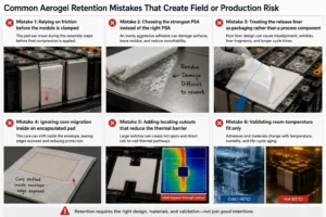
Common Aerogel Retention Mistakes That Create Field or Production Risk
Mistake 1: Relying on friction before the module is clamped
Final stack compression may be excellent, but the pad can still move during the two or three assembly steps before that compression exists. Temporary retention needs to be designed into the workstation, part, or module geometry.
Mistake 2: Choosing the strongest PSA instead of the right PSA
More peel strength is not automatically more reliability. The adhesive must match substrate energy, thermal aging, chemical exposure, dielectric requirements, rework strategy, and the desired compliance of the stack. Excessively aggressive adhesive can also damage a fragile carrier or make prototype iteration unnecessarily difficult.
Mistake 3: Treating the release liner as packaging rather than a process component
Liner shape, split position, pull-tab length, and peel direction directly affect placement accuracy and cycle time. Many assembly problems can be solved by changing liner architecture without changing the aerogel core at all.
Mistake 4: Ignoring core migration inside an encapsulated pad
An outer film can stay in place while the aerogel core shifts within the envelope if the internal construction is not controlled. Define how the core is registered, bonded, sealed, or constrained inside the laminate and inspect core-to-envelope position after aging and vibration.
Mistake 5: Adding locating cutouts that reduce the thermal barrier
Large notches may make assembly easier but expose direct cell-to-cell pathways. Every cutout should have a functional reason and should be reviewed against the thermal model. Whenever possible, put locating features in carrier extensions outside the required thermal coverage.
Mistake 6: Validating room-temperature fit only
A pack is not a room-temperature fixture. Adhesives soften or stiffen, films shrink or expand, cells swell, and module preload evolves. Retention validation needs environmental and life-cycle conditions, not just a golden sample on the bench.
Industry Insight: Aerogel Retention Is Becoming a System-Level Requirement
The EV industry is moving from material selection toward integrated thermal-propagation architecture. Commercial barrier suppliers emphasize compression durability, vibration/shock resistance, and encapsulated constructions—not only thermal conductivity. Patent activity similarly shows adhesive layers, assembly-pressure retention, integrated holding portions, and mechanically captured barriers. The direction is clear: the market increasingly expects the insulation part to be designed for the mechanical life of the battery, not merely to survive a flame or hot-plate test.
This matters even more under tightening battery-safety expectations. China’s GB 38031-2025 traction-battery safety standard became effective on July 1, 2026 and strengthened thermal-propagation safety requirements compared with the 2020 edition. The standard does not prescribe ‘use PSA on aerogel,’ but the engineering implication is important: every passive barrier must perform as installed. A high-performance material that migrates away from its intended location cannot deliver the protection assumed by the module design.
For sourcing teams, this shifts the supplier question from ‘Can you cut aerogel?’ to ‘Can you deliver an automotive-ready converted part with controlled laminate thickness, adhesive location, edge construction, positioning features, clean handling, traceability, and repeatable validation data?’ That is a much higher-value capability—and it is where precision die-cutting and lamination become part of battery safety engineering.
What Should Be Included in an RFQ for Anti-Shifting Aerogel Pads?
A detailed RFQ shortens DFM time and prevents the supplier from optimizing the wrong parameter. Send the information below even if some values are preliminary.
- Cell type and module architecture: prismatic, pouch, cylindrical grouping, cell count, orientation, and stack direction.
- Aerogel function: cell-to-cell propagation barrier, module side barrier, end-plate insulation, pack-lid insulation, or multi-function spacer.
- Required nominal thickness and allowed compressed-thickness window.
- Required thermal coverage area and all keep-out zones for vents, terminals, busbars, sensors, cooling interfaces, and fasteners.
- Expected beginning-of-life and end-of-life stack pressure or cell-swelling envelope.
- Retention preference: no adhesive, one-side PSA, two-side PSA, patterned adhesive, carrier tabs, frame capture, or open to DFM recommendation.
- Substrate material and surface finish to be bonded: coated aluminum cell can, polymer film, PC frame, mica, foam, metal enclosure, etc.
- Environmental conditions: temperature range, humidity, thermal cycling, vibration/shock requirement, and chemical exposure concerns.
- Assembly sequence: manual placement, robot pick-and-place, cell stacking order, liner removal method, temporary fixtures, and takt time.
- Quality documents: PPAP level, control plan, material certificates, dimensional Cpk requirements, lot traceability, and change-control expectations.
- Drawing files: DXF/DWG/STEP/PDF plus critical-to-quality dimensions and tolerance notes.
- Prototype quantity, validation schedule, target SOP volume, and annual demand.
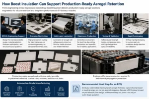
How Boost Insulation Can Support Production-Ready Aerogel Retention
Boost Insulation positions its aerogel business around more than raw material supply. The company states that its engineering team provides DFM review for aerogel insulation, including optimization of material selection, thickness, and structural layout. Its current manufacturing scope includes die-cutting, CNC processing, multi-layer lamination of aerogel with adhesive and protective films, controlled cleanroom production, adhesive peel-strength testing, high-temperature aging, and rapid prototyping.
That combination is useful for pad-retention projects because the retention mechanism often belongs in the converted part. Instead of asking an assembly plant to separately buy aerogel, adhesive tape, carrier film, release liner, and a locating frame, the part can be engineered as a ready-to-place subassembly. Depending on the design, Boost can support one-side or patterned adhesive constructions, protective film lamination, custom tabs and notches, kiss-cut liners, and precision geometry that matches the module datum strategy.
For EV battery module programs, Boost also states that it supports automotive-grade manufacturing workflows including IATF 16949, APQP/PPAP support, lot traceability, cleanroom die-cutting and assembly, in-house tooling, and 48-hour rapid prototyping for custom parts. These capabilities are particularly relevant when the engineering team needs to iterate liner geometry, adhesive coverage, corner radii, tabs, or multi-layer stack-up before locking production tooling.
Recommended next step for an RFQ: Send the cell/module drawing, target aerogel thickness, expected compression or swelling range, and your current assembly sequence. Ask for a DFM review focused specifically on pad retention, liner design, and thermal keep-out zones—not only an outer-shape quotation.
Conclusion: Keep the Barrier Where the Thermal Model Put It
Preventing aerogel pads from shifting in EV packs is a mechanical-design and manufacturing problem as much as a materials problem. PSA can make assembly much more reliable, but adhesive should not automatically be the only retention mechanism. Encapsulation improves handling and dimensional stability; tabs and frame features provide positive location; and controlled stack compression can provide durable retention after the module is clamped. The most robust automotive design often combines these methods so no single process variation can move the barrier into a dangerous position.
If your current aerogel pad slides during cell stacking, lifts at the corners, wrinkles under compression, sheds dust, or requires too much manual alignment, the fix may be a relatively small DFM change: a different carrier film, a patterned PSA, a split release liner, a locating tab, a revised edge seal, or a tolerance adjustment. Those changes are far easier to implement before tooling and validation are frozen.
Need a custom aerogel pad that stays positioned through assembly and vehicle life? Send your drawing and module requirements to Boost Insulation for a manufacturability review and prototype recommendation. Request a quote or upload your design file.
Frequently Asked Questions
Can you use double-sided adhesive on aerogel pads in an EV battery pack?
Yes, some barrier constructions can use adhesive on one or both sides, but double-sided bonding should be selected carefully. It can improve placement stability, yet it also couples the barrier mechanically to two moving cell surfaces. If the cells need to breathe or swell independently, a one-side adhesive plus stack compression may be easier to control. Validate the actual adhesive, substrate, compression, thermal cycling, and service strategy before choosing two-sided bonding.
Is stack compression alone enough to keep aerogel from moving?
It can be, especially after the cell stack is fully clamped. Published battery thermal-sheet designs note that assembly pressure can hold stacked components in place without exposed adhesive.[6] The risk is the assembly period before full preload exists and any life-cycle condition that reduces local pressure. If the part can move before clamping, use temporary adhesive, a fixture, or a mechanical locating feature.
Why are aerogel pads often encapsulated in film?
Encapsulation improves handling, contains dust, protects the edges, and creates a stable surface for adhesive, printing, and automated placement. It can also make the pad easier to integrate with compression foam or other layers. Commercial EV battery products are available as encapsulated aerogel pads for intercell use.
What is the best way to stop a pad from sliding during prismatic-cell stacking?
A practical solution is to attach the pad lightly to the first cell with a thin, validated PSA, add a tab or datum feature if space permits, and design the module so final stack compression holds the barrier after assembly. This gives the line a stable part during insertion without making the adhesive solely responsible for long-term retention.
How much pad movement is acceptable after vibration testing?
There is no universal displacement value because the acceptable shift depends on the thermal coverage margin, cell geometry, and OEM specification. Define the maximum allowable X-Y movement from the thermal model and keep-out zones, then measure the pad location before and after vibration, shock, and environmental aging. A visible ‘still there’ inspection is not precise enough for a critical barrier.
Can Boost Insulation make adhesive-backed or laminated aerogel parts?
Boost Insulation states that its aerogel manufacturing services include multi-layer lamination of aerogel, adhesive, and protective films, precision die-cutting, cleanroom production, adhesive peel-strength testing, and rapid prototyping. For a specific project, the final construction should be confirmed through drawing review, material validation, and DFM before production release.
Technical References and Editorial Verification
- Aspen Aerogels – Thermal Runaway Barriers — Notes compression performance, compression-fatigue resilience, vibration/shock durability, and EV thermal-runaway barrier use. Source
- Saint-Gobain Tape Solutions – EV Battery Cell / TRP Pads — Lists an encapsulated aerogel intercell pad and discusses cell breathing/swelling and mechanical behavior. Source
- Google Patents – US20230282905A1, Battery Cell Thermal Runaway Barrier — Describes optional hot-melt or pressure-sensitive adhesive on encapsulated thermal barriers with release liners. Source
- Google Patents – EP4113714A1, Intercell Spacer and Battery Module — Describes a holding portion that makes a heat-resistant barrier easier to fix in position during module assembly. Source
- Google Patents – US20250062444A1, Thermal Barrier Assembly for Traction Battery Pack — Illustrates mechanically integrated thermal-barrier fingers/slots around battery terminal features. Source
- Google Patents – WO2021183493A1, Thermal Management Multilayer Sheet for a Battery — States that sheets can be placed or adhered and that battery assembly pressure can hold stacked components in place. Source
- China National Standard Information Public Service Platform – GB 38031-2025 — Official record: published March 28, 2025; effective July 1, 2026; replaces GB 38031-2020. Source
- Boost Insulation – Aerogel Insulation — Current Boost page describing DFM, lamination, die-cutting, cleanroom production, adhesive peel testing, high-temperature aging, and rapid prototyping. Source
- Boost Insulation – EV Battery Module Insulation / Home — Current Boost page describing automotive-grade production, IATF 16949, cleanroom manufacturing, prototyping, and EV module support. Source
Related Posts:
When Should EV Battery Packs Use Mica Instead of Aerogel?
How Is Aerogel Used Near EV Battery Module End Plates?
How Does FR Polycarbonate Compare to Flame Retardant PVC?
How Do You Test Silicone Foam Recovery in EV Battery Pads?
Why Do EV Battery Packs Use a Mica Insulation Sheet?
How to Choose EV Battery Cell Insulation Pads?
 betty wong
