Rotary vs. Flatbed Die Cutting for Electrical Insulation
Table of Contents
⚑ QUICK ANSWER
Electrical insulation components are rarely interchangeable with ordinary packaging die cuts. A slot may establish clearance from a busbar, an adhesive island may control installation, and a particle at a critical edge may trigger additional inspection. The production route must therefore be selected from the finished-part drawing and acceptance criteria, not from a generic machine comparison. This guide focuses on the decision engineers must document before tooling approval, including cost per accepted part, material utilization, feature capability, and process-transfer evidence.
Rotary vs. Flatbed Die Cutting: Which Is Better for Electrical Insulation?
Table 1 — Rotary vs. Flatbed Die Cutting: Engineering Comparison
| Selection factor | Rotary die cutting | Flatbed die cutting | Engineering implication |
| Material feed | Typically continuous roll/web | Often sheet-fed; some roll-fed designs | Confirm incoming format and maximum working width. |
| Tool form | Solid rotary or flexible die on cylinder | Flat steel-rule or precision punch tool | Tool design changes cost and achievable detail. |
| Production economics | May spread higher fixed cost over large runs | May reduce initial investment for changing designs | Compare annual accepted parts, not theoretical speed. |
| Material flexibility | Web tension and bendability are constraints | Sheet support can favor rigid or thick stock | Trial the exact grade and construction. |
| Registration | Web guidance, pitch, and die timing matter | Sheet locating and stroke repeatability matter | Use part-specific capability data. |
| Adhesive/liner | In-line kiss cut and stripping are possible | Kiss cutting also possible with suitable setup | Verify layer-selective cut depth. |
| Scrap behavior | Continuous matrix removal can be limiting | Sheet skeleton/part extraction can be limiting | Model yield and waste handling. |
| Change management | Tooling and station setup may affect revisions | Tool revisions may be simpler for some jobs | Evaluate revision frequency and validation cost. |
INDUSTRY INSIGHT 01 | Faster Cutting Does Not Always Mean Lower Total Cost
Engineering observation: Quoted machine speed is not the same as shipped, accepted parts per hour. Setup, startup waste, stoppages, inspection, and packaging all consume capacity.
Why it matters: A faster line can lose its cost advantage on short campaigns or frequent revisions.
Practical recommendation: Ask for a costed process route and effective cost per accepted part at your forecast quantities.
How Do Rotary and Flatbed Die Cutting Work?
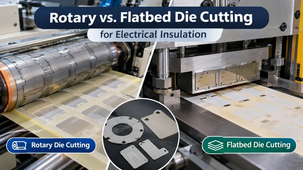
Rotary die cutting passes a moving web between a cutting cylinder and an anvil. Depending on equipment, the die may be solid or a replaceable flexible plate mounted on a magnetic cylinder. Web guiding, unwind/rewind control, registration, slitting, lamination, and waste-matrix removal can be integrated into the line. The actual configuration determines whether a given job can be full-cut, kiss-cut, or converted into liner-carried parts.
Flatbed die cutting presses a flat tool into supported material in a reciprocating or platen action. A flatbed press can be sheet-fed or, in certain configurations, part of a roll-fed converting line. Steel-rule dies are common, but precision tooling choices vary. A sheet format can simplify support for stock that would crack, distort, or exceed the bending limits of a web path. Neither term describes a single universal equipment specification.
Engineering Comparison: Accuracy, Thickness, Geometry, and Production Speed
A machine brochure may advertise a positioning or repeatability number, but the drawing specifies a finished-part tolerance. Those are different quantities. Film stretch, die wear, temperature, adhesive flow, liner compression, measurement force, and post-cut relaxation can all change the result. Establish datums and inspect parts in a defined condition—for example, liner-on after a specified conditioning period—before claiming process capability.
For thin flexible films, rotary web tension may create lengthwise dimensional changes; a stable material and controlled tension can make this manageable. For thicker or fragile laminates, the bending path itself may be the limiting factor. Flatbed cutting avoids some web-path constraints but introduces its own positioning, pressure-distribution, ejection, and sheet-handling variation. A close-tolerance drawing needs an agreed inspection method and a trial on production-representative material.
Table 2 — Die-Cutting Accuracy and Geometry Review Matrix
| Design requirement | Rotary risk | Flatbed risk | Verification method |
| Hole-to-edge datum | Web stretch or register drift | Sheet locating or tool shift | First/last-off coordinate measurement |
| Narrow bridges | Matrix tearing during stripping | Ejection damage or part retention | Microscope plus removal trial |
| Internal slots | Slug removal and anvil contact | Slug packing and incomplete cut | 100% slot presence where critical |
| Small corner radius | Die feature durability | Rule bending and material fracture | Tool review and edge microscopy |
| Adhesive island | Liner strike or adhesive stringing | Uneven cut depth or adhesive pickup | Peel, liner, and layer inspection |
| Long dimension | Machine-direction stretch | Sheet expansion or distortion | Conditioned dimensional study |
| Critical edge quality | Cut lip, dust, delamination | Compression, chipping, ejection mark | Agreed defect standard and sampling |
INDUSTRY INSIGHT 02 | Material Construction Can Decide the Process Before Volume Does
Engineering observation: A roll-compatible base film may become difficult to convey after adding a stiff backing, brittle coating, or thick foam layer.
Why it matters: Quoting from the base-material name alone can produce an infeasible production route.
Practical recommendation: Send a layer-by-layer stack drawing, material form, winding limits, and representative samples before process selection.
INDUSTRY INSIGHT 03 | Accuracy Is a Process-System Capability
Engineering observation: A precision die cannot compensate for unstable web tension, poor sheet locating, or an inconsistent inspection method.
Why it matters: The same nominal tool can deliver different finished dimensions on different constructions.
Practical recommendation: Qualify the full material–tool–machine–inspection system against the actual critical-to-function dimensions.
Which Process Fits PC, PET, PI, Mica, and Other Insulation Materials?
Material names are useful screening categories, not final process prescriptions. Two PC films can differ in thickness, coating, stiffness, protective liner, and surface treatment. A mica composite may be flexible in a thin tape form but brittle as a reinforced sheet. The correct comparison therefore includes grade, construction, incoming format, tool support, and required edge condition. The matrix below identifies trials to request rather than universal approvals.
Table 3 — Electrical Insulation Material-to-Process Compatibility
| Material / construction | Rotary considerations | Flatbed considerations | Key DFM risk |
| PC / FR-PC film | Good candidate when roll-fed and tension-stable | Useful for sheets and frequent geometry changes | Stress whitening, web stretch, edge cracks |
| PET film | Roll converting and liner integration possible | Sheet conversion and lower-volume work possible | Stretch, curl, static, thin-web tearing |
| PI film | Thin flexible rolls can suit rotary lines | Precision sheet work also feasible | Small-feature tearing, adhesive stringing |
| Mica laminate | Only if grade/stack flexes safely through web path | Often considered for supported rigid sheets | Cracking, dust, edge chipping |
| Aramid paper | Web-fed conversion may be practical | Sheet handling may suit special profiles | Fiber pullout and dimensional moisture effects |
| FR4 / rigid laminate | Usually limited by rigidity and equipment geometry | May require specialized punching or CNC instead | Edge fracture, tool wear, particulate |
| Aerogel composite | Only with compatible carrier and dust controls | Supported sheets may reduce handling stress | Powder release, compression damage |
| Silicone foam | Web route possible with liner and controlled compression | Sheet route may help thick constructions | Dimensional recovery and adhesive transfer |
| Adhesive-backed film | In-line kiss cutting and matrix removal possible | Selective-layer cutting also possible | Liner damage, adhesive ooze, lift |
| Multilayer laminate | Register each layer and manage tension | Control stack pressure and ejection | Interlayer shift and delamination |
Rotary vs. Flatbed Tooling Cost: When Does Each Become More Economical?
A useful economic comparison separates one-time fixed costs, per-campaign costs, and per-accepted-part variable costs. Fixed costs include initial tooling and qualification fixtures; campaign costs include setup and startup activities; variable costs include purchased material, conversion labor/machine time, and the material consumed in rejects. If a supplier quotes a lower processing rate but requires more expensive stock or creates more scrap, its total project cost may still be higher.
For a defined planning period, a practical model is: Total project cost = tooling + campaign setups + material + processing + scrap/quality costs. When material and processing costs are calculated per attempted part and yield is measured as accepted parts divided by attempts, use Cost per accepted part = (fixed cost / accepted quantity) + (material per attempt + processing per attempt) / accepted yield. Avoid double-counting rejects: either account for rejects through yield or add separately documented scrap costs, not both.
If F is the flatbed route and R is the rotary route, the break-even accepted quantity is Q_BE = (Fixed_R − Fixed_F) / (Variable_F − Variable_R), provided rotary has higher fixed cost but lower variable cost. A negative or undefined result means the assumed tradeoff does not create a positive break-even point. This equation is a decision aid, not a market price forecast.
Table 4 — Manufacturing Cost Model: What to Compare
| Cost driver | Rotary cost consideration | Flatbed cost consideration | Decision impact |
| Initial tooling | Solid/flexible die and cylinder compatibility | Steel-rule or other flat tooling | Amortize across life-of-program quantity |
| Campaign setup | Web threading, register, waste path | Sheet locating, pressure and ejection | Frequent short runs change economics |
| Material purchase | Roll width, repeat and usable yield | Sheet nesting and offcut recovery | Often dominates expensive films |
| Conversion labor | In-line operations may reduce touches | Handling and part removal may add touches | Count all stations and operators |
| Accepted yield | Matrix breaks, web defects, liner damage | Misfeeds, ejection damage, incomplete cut | Rejects increase effective unit cost |
| Quality / change | Tool wear and requalification | Tool adjustment and revision effort | Include validation and inspection burden |
INDUSTRY INSIGHT 04 | Scrap Can Matter More Than Machine Speed
Engineering observation: For expensive PI or engineered laminate, a few points of material utilization can outweigh a difference in cutting cycle time.
Why it matters: Material cost is incurred before a rejected or unusable piece becomes a saleable part.
Practical recommendation: Compare purchased-area yield and accepted-part yield separately; report both in the quotation model.
INDUSTRY INSIGHT 05 | Tooling Should Be Judged Over Product Life, Not the First Order
Engineering observation: A 2,000-piece pilot and a 200,000-piece annual program can favor different processes even when the drawing is identical.
Why it matters: Ignoring lifecycle volume can lock a program into avoidable handling costs or premature tooling expense.
Practical recommendation: Model prototype, ramp, steady state, expected revisions, and tool replacement as separate scenarios.
How Do Material Yield and Scrap Rates Change the Decision?
Two yields must not be confused. Layout utilization is the fraction of purchased material area assigned to intended part blanks; it is affected by nesting, pitch, edge trim, and web width. Process acceptance yield is the fraction of attempted parts that pass inspection. A process can have excellent cycle speed and poor layout utilization, or efficient nesting but unacceptable registration loss. Report both values and the measurement basis.
For rotary conversion, the usable web width, repeat length, cross-web spacing, matrix strength, and splice policy govern consumption. For flatbed conversion, sheet dimensions, edge clamps, nest orientation, skeleton strength, and extraction losses matter. If an adhesive-backed film needs pull tabs or carrier strips, those features belong in the material-yield calculation rather than being treated as invisible packaging overhead.
What Quality Problems Occur in Rotary and Flatbed Die Cutting?
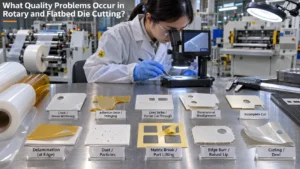
Cutting quality is not one dimension. A part can meet its outer profile and still fail because of a partially cut liner, debris, adhesive contamination, or an edge defect at a critical insulation boundary. The converter and design owner should agree on defect definitions, inspection magnification, sampling, measurement condition, and disposition rules before production approval.
Table 5 — Die-Cutting Defect and Failure Mode Matrix
| Failure mode | Potential cause | Functional risk | Prevention / inspection |
| Crack or stress whitening | Sharp radius, blade load, material strain | Reduced edge integrity at critical zone | Trial corner radii; magnified edge review |
| Adhesive ooze/stringing | Soft PSA, heat, wrong peel geometry | Contamination or poor placement | Conditioning; cut-depth and peel trials |
| Liner strike / cut-through | Caliper variation or excessive penetration | Transfer failure or web break | Liner impression standard; peel test |
| Dimensional drift | Tension, humidity, tool movement | Misalignment or insufficient coverage | Time-series CTF measurements |
| Incomplete cut | Uneven pressure or tool wear | Torn part during removal | First/last-off and cavity sampling |
| Delamination | Layer mismatch or ejection load | Loss of construction integrity | Cross-section and peel inspection |
| Dust / fibers / particles | Brittle composite or worn tooling | Cleanliness and assembly risk | Cleanliness specification and containment |
| Matrix break / part lift | Weak skeleton, peel angle, tack | Scrap entanglement and rejected parts | Stripping-path trial and defect logging |
| Edge burr or lip | Tool condition or compressive deformation | Interference or local damage | Edge profile acceptance sample |
| Surface dent / curl | Handling pressure or poor packaging | Fit and installation instability | Flatness, packaging, post-ship checks |
Inspection should be risk-based. A cosmetic mark on a noncritical face is not automatically an electrical failure, while a tiny tear adjacent to a high-voltage interface may require rejection. Document the engineering rationale rather than adopting a blanket “zero visible marks” requirement that cannot be measured consistently. Where contamination matters, specify particle type, size, count, and test method appropriate to the assembly.
INDUSTRY INSIGHT 06 | Edge Quality Is Part of Functional Quality
Engineering observation: Geometry and edge condition can affect assembly coverage even when the raw dielectric film meets its datasheet requirements.
Why it matters: Uncontrolled tears, particles, or raised edges may change the installed condition or trigger downstream defects.
Practical recommendation: Classify critical edges on the drawing and define a measurable edge-inspection criterion.
INDUSTRY INSIGHT 07 | Adhesive-Backed Films Need More Than Dimensional Inspection
Engineering observation: A perfectly shaped film can fail during transfer because the liner is overcut or the adhesive strings across a slot.
Why it matters: The delivered construction includes the adhesive, liner, and presentation format—not just the polymer film.
Practical recommendation: Validate liner release, kiss-cut depth, adhesive-free zones, and pick-and-place behavior on the final stack.
How Does Process Selection Affect Electrical Insulation Performance?
Die cutting does not automatically change a polymer’s intrinsic dielectric properties. It can, however, change the finished insulation component through geometry errors, edge damage, contamination, adhesive placement, or installation variation. An insulation barrier with a correctly specified film but an oversized hole can leave a conductor insufficiently covered. A liner-cut defect may cause the part to stretch or tear during assembly.
The relevant acceptance criteria must follow the electrical design: critical edge coverage, separation from conductive features, material continuity, and the required component or assembly tests. Dielectric strength data from ASTM D149 or IEC 60243-1 can help characterize insulating materials, but they do not by themselves establish safe working voltage or validate a die-cut assembly. UL 94 classifications address material flammability under defined conditions, not whether the finished part meets the complete electrical safety requirements.
Where the design relies on creepage or clearance, review the actual assembled geometry under the applicable product requirements. A converter can verify dimensional features and surface condition, but the product owner must establish insulation coordination, operating environment, test conditions, and system acceptance criteria. The boundary between converter inspection and system validation should be explicit in the control plan.
Can Flatbed Prototypes Be Transferred to Rotary Mass Production?
Yes, but process transfer should be treated as a controlled manufacturing change, not an administrative substitution. Even with the same CAD file and nominal material, the feed direction, tool contact, waste-removal method, and part presentation may differ. A prototype that passes a fit check does not prove that rotary production will preserve the same critical features, liner behavior, or electrical function.
Create a golden-sample comparison plan before the rotary tool is ordered. Compare material lot and construction, drawing revision, datum scheme, feature locations, edge quality, adhesive registration, dimensional conditioning, liner removal, and packaging. For critical characteristics, use an agreed measurement-system study and production-representative capability evidence; do not apply arbitrary Cpk targets without customer requirements and adequate statistical design.
Table 6 — Prototype-to-Production Process Transfer Checklist
| Review item | Required evidence | Potential risk | Release action |
| Drawing and datum | Controlled revision; CTF list | Different interpretation of nominal CAD | Approve common inspection plan |
| Material and layer stack | Same approved grade and layer orientation | Construction mismatch | Document and approve substitution |
| Feed / grain direction | Orientation map and sample comparison | Stretch, curl, anisotropic response | Run oriented material trial |
| Tool and cut depth | First-article records; liner standard | Liner strike, incomplete cut | Approve cut-depth window |
| Geometry correlation | Paired measurements across cavities | Systematic dimensional shift | Update tool or tolerance study |
| Edge and cleanliness | Photos; agreed defect limits | New burr, dust, cracks | Pass edge/particle validation |
| Assembly performance | Peel, pickup, installation trials | Part lift, liner transfer failure | Validate on representative fixture |
| Production readiness | Control plan; traceability; change log | Uncontrolled drift after ramp | Approve release gate and monitoring |
INDUSTRY INSIGHT 08 | Process Transfer Creates New Failure Modes
Engineering observation: A flatbed sample may have been removed by hand while rotary parts are stripped continuously and delivered on a liner.
Why it matters: Different removal forces and feed-direction strains can alter the defect population.
Practical recommendation: Use a transfer-specific validation matrix instead of assuming the original prototype approval covers the new route.
INDUSTRY INSIGHT 09 | The Measurement State Must Be Specified
Engineering observation: Film dimensions can differ immediately after cutting, after relaxation, and after liner removal.
Why it matters: Two suppliers can report conflicting but internally correct measurements if the inspection state is undefined.
Practical recommendation: Specify conditioning time, temperature, liner-on/off state, measurement force, and datum orientation.
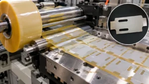
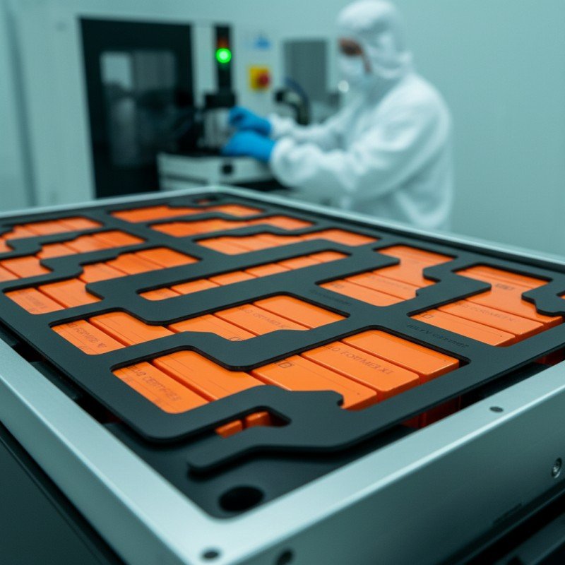
Hypothetical Engineering Case Study: EV Battery Module Insulation Film
Illustrative assumptions—not customer data, industry averages, or Boost quotations. Consider a die-cut, adhesive-backed FR-PC barrier with a 95 × 62 mm outline, two internal slots, a controlled busbar-edge location, and a release liner for assembly. Assume a 0.25 mm base film, a 0.05 mm adhesive layer, and a 0.075 mm liner solely to describe the example stack. The design owner defines an illustrative ±0.20 mm tolerance on one critical location; this is not a recommended universal tolerance.
The engineering team can obtain a flatbed prototype quickly, but the forecast is 120,000 accepted parts per year. Both routes pass an initial feasibility screen for this particular hypothetical material. The quote team evaluates one production campaign and a one-time tooling charge in year one. The ideal-area raw material cost is assumed to be $0.18 per intended blank before nesting losses; layout utilization is 72% flatbed and 82% rotary. Accepted yields are assumed to be 97.5% and 98.5%, respectively.
Cost assumptions: Flatbed tooling $850; campaign setup $180; processing $0.155 per attempted part. Rotary tooling $4,800; campaign setup $400; processing $0.065 per attempted part. Material per attempted part equals $0.18 divided by layout utilization. Rejected material and conversion are already included through accepted yield; no additional warranty or field-quality cost is assumed. These figures are deliberately hypothetical and require supplier quotations.
Flatbed: fixed cost = $1,030; variable cost per accepted part = ($0.18 / 0.72 + $0.155) / 0.975 = $0.4154. Rotary: fixed cost = $5,200; variable cost per accepted part = ($0.18 / 0.82 + $0.065) / 0.985 = $0.2888. The break-even accepted quantity is ($5,200 − $1,030) / ($0.4154 − $0.2888) ≈ 32,954 accepted parts. Rounding explains minor differences from spreadsheet calculations.
At 10,000 accepted parts, estimated total cost is about $5,184 flatbed versus $8,088 rotary; flatbed is favored. At 120,000 accepted parts, the totals are approximately $50,876 flatbed versus $39,861 rotary, favoring rotary by about $11,015 under the assumed conditions. The result is a first-year, one-campaign comparison; multiple setups, tool replacements, inventory costs, or design changes would alter it.
Sensitivity check: If rotary layout utilization falls to 72% and accepted yield to 96% while other assumptions stay fixed, its variable cost rises to ($0.18 / 0.72 + $0.065) / 0.96 = $0.3281. The break-even volume moves to approximately 47,788 accepted parts. Rotary still wins at 120,000 parts, but the margin narrows. A forecast below that revised threshold could change the preferred route. The lesson is to test the business case against yield and volume uncertainty, not merely compare tool prices.
Engineering release decision: Select rotary as the provisional production route only after a controlled trial confirms the critical slot-to-edge dimension, liner integrity, adhesive registration, matrix stripping, cleanliness, and assembly pickup. Keep flatbed as a prototype or contingency option. If the rotary trial fails a critical characteristic, the lower modeled cost does not justify release; resolve the failure, redesign the presentation, or reconsider the process.
INDUSTRY INSIGHT 10 | The Lowest Quoted Piece Price Is Not the Lowest-Risk Route
Engineering observation: A cost model can favor rotary while a critical liner-transfer failure remains open.
Why it matters: An inexpensive rejected part—or a part that disrupts assembly—does not create economic value.
Practical recommendation: Apply a technical release gate first, then compare total cost only among validated feasible routes.
Rotary vs. Flatbed Die Cutting: Engineering Selection Checklist
Use this checklist in the process-selection meeting. Record Pass, Fail, or Open against each item and attach objective evidence. An open issue on a critical insulation boundary, material integrity, or customer-required characteristic should block tooling or production release until the design owner approves a disposition.
- Material: exact grade, thickness range, layer stack, adhesive, liner, supply format, and bend/handling limits are defined.
- Geometry: critical-to-function dimensions, slots, bridges, radii, and edge coverage are identified on a controlled drawing.
- Process feasibility: supplier has trialed the actual construction on representative equipment and tooling.
- Quality: edge defects, contamination, liner damage, and dimensional inspection state have measurable acceptance criteria.
- Economics: layout utilization, acceptance yield, fixed costs, campaigns, and lifecycle volumes use comparable assumptions.
- Transfer: prototype and production processes are correlated through first-article, assembly, and functional checks.
- Release: open risks, ownership, traceability, change control, and production monitoring are documented.
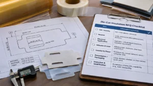
How Should Engineers Prepare an RFQ for Electrical Insulation Die Cutting?
A useful RFQ allows the converter to propose a process rather than forcing an untested one. Supply a controlled 2D drawing (PDF plus DXF or another agreed native format), critical-to-function datums, material construction, and acceptance criteria. Include prototype quantity, annual accepted demand, release schedule, and expected number of campaigns. Specify whether parts must be supplied loose, sheeted, stacked, or liner-carried for automated installation.
Table 7 — Electrical Insulation Die-Cutting RFQ Checklist
| Required information | Why it matters | Supplier confirmation | Risk if missing |
| CAD, PDF, datums, tolerances | Defines inspectable finished geometry | Revision and CTF feasibility | Wrong feature or tool interpretation |
| Material grade and stack | Controls feed, tool, cut depth | Exact construction and availability | Infeasible route or layer damage |
| Electrical application | Identifies critical edges/coverage | Inspection boundaries and responsibilities | Hidden functional risk |
| Adhesive and liner details | Controls kiss cut and part transfer | Peel/liner strategy and orientation | Assembly and matrix failures |
| Quantity by phase | Sets fixed-cost amortization | Prototype, ramp, annual quote tiers | Misleading unit-cost comparison |
| Presentation / packaging | Affects automation and damage | Carrier pitch, stacking, labeling | Downstream handling loss |
| Inspection and qualification | Defines acceptance evidence | FAI, capability, traceability plan | Unverifiable quality promises |
How Boost Insulation Supports Precision Die-Cut Insulation Components
Boost Insulation publicly describes precision die-cutting, rotary converting, CNC processing, lamination, in-house tooling, and DFM support for electrical insulation and EV battery components. Its flame-retardant polycarbonate product page and EV battery module insulation page provide application context. Public pages do not establish the exact flatbed equipment configuration for every project; customers should request confirmation during feasibility review.
Frequently Asked Questions
What is the difference between rotary and flatbed die cutting?
Rotary die cutting typically uses a rotating cutting cylinder and a moving material web, often with integrated lamination and waste removal. Flatbed cutting uses a reciprocating or platen-style tool against supported stock. Both can produce electrical insulation parts. The relevant differences are material handling, tooling configuration, process stability, accepted-part yield, and total cost for the specified drawing.
Is rotary die cutting more accurate than flatbed die cutting?
Not inherently. Rotary equipment can achieve excellent repeatability on stable rollstock, but web tension, tool condition, registration, and liner behavior influence final dimensions. Flatbed accuracy depends on sheet location, pressure, tool construction, and part extraction. Compare actual capability data on the same material and critical features, measured in the same condition, rather than relying on advertised machine accuracy.
Which die-cutting process is better for electrical insulation films?
For flexible PC, PET, or PI film supplied in rolls, rotary cutting may be attractive when recurring demand and in-line handling justify its setup. Flatbed cutting can suit sheet-fed stock, evolving designs, or difficult material constructions. Confirm the specific grade, thickness, adhesive stack, feature geometry, edge-quality limits, and accepted production volume before selecting either route.
Is flatbed die cutting better for thick insulation materials?
Flatbed cutting often offers practical advantages for thick, stiff, or sheet-form materials because they do not need to follow a tight web path. That is not a universal thickness rule: tooling force, blade geometry, reinforcement, part size, and material fracture behavior still matter. Very rigid or abrasive laminates may require CNC or another method instead of either die-cutting approach.
When is rotary die cutting more cost-effective?
Rotary cutting becomes economically attractive when its lower validated variable cost per accepted part offsets additional tooling and campaign expense. Calculate break-even volume from quoted fixed costs and accepted-part variable costs. Include material utilization, rejects, setup frequency, and lifecycle demand. A high machine speed alone does not establish a lower total cost, especially for short or frequently revised orders.
Can adhesive-backed insulation films be rotary die cut?
Yes, many adhesive-backed films can be rotary converted, including selective-layer kiss cutting when the machine and tooling are suitable. The liner thickness, adhesive rheology, cutting clearance, matrix stripping, and part presentation must be validated. A correct outer profile is insufficient if the liner is damaged, adhesive strings across openings, or the part lifts during automated transfer.
Can a flatbed die-cut prototype be transferred to rotary production?
Yes, but transfer requires a documented correlation exercise. Verify the same material construction, controlled CAD revision, feed orientation, critical dimensions, edge quality, liner release, adhesive placement, and assembly behavior. Rotary introduces web tension and continuous matrix removal that may not exist in a flatbed prototype. Approve the new route only after representative production trials and required validation evidence.
What information does a supplier need to select the right die-cutting process?
Provide the controlled drawing, material grade and complete layer stack, nominal and minimum thicknesses, critical tolerances, electrical function, adhesive and liner specifications, prototype quantity, annual demand, packaging format, and inspection requirements. Include any known cracking, contamination, registration, or transfer problems. With those inputs, the converter can assess process feasibility and compare total accepted-part cost.
Final Recommendation: Select the Validated Process, Not the Faster Machine
Choose rotary when the actual construction can run reliably as a web, critical features are stable, in-line operations improve handling, and lifecycle accepted volume supports the investment. Choose flatbed when supported sheet processing, geometry changes, thick or stiff constructions, or shorter campaigns make it the more robust route. When both are feasible, calculate the break-even point using accepted parts, then verify the selected process against the drawing and assembly requirements.
Need a manufacturing feasibility review for a custom electrical insulation part? Send Boost Insulation your CAD/PDF drawing, material and layer specifications, critical dimensions, adhesive/liner details, sample quantity, annual forecast, and quality requirements through the contact page. Ask for a DFM assessment and a process recommendation supported by part-specific trial evidence.
Related Posts:
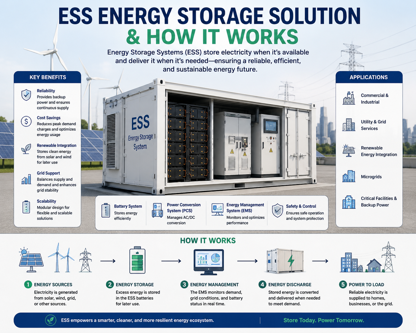
What Is ESS Energy Storage Solution & How It Works?
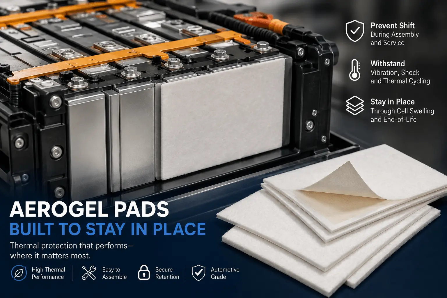
How Do You Prevent Aerogel Pads From Shifting in EV Packs?
How Does FR4 Support EV Battery Contactors and Fuses?
How Does Mica Prevent Dielectric Breakdown in EV Batteries?
What Is a Mica Insulation Sheet for EV Battery Packs?
How to Choose EV Battery Cell Insulation Pads?
 root