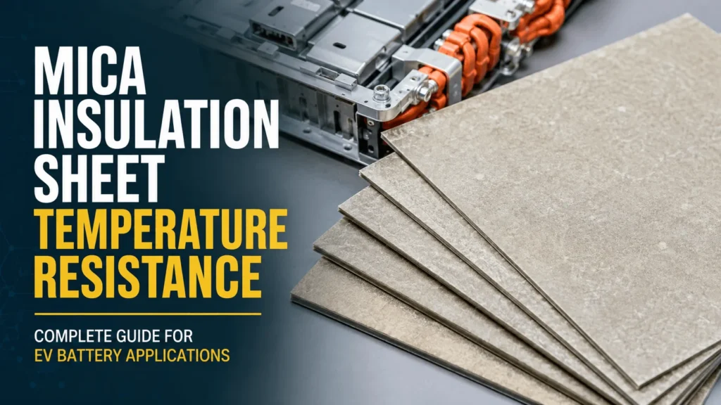
What Temperature Can a Mica Insulation Sheet Withstand?
Table of Contents
A mica sheet may be advertised as capable of handling 1,000°C, yet the same part can curl, delaminate, or lose adhesion at a much lower temperature inside an EV battery pack. Is the datasheet wrong? Usually not. The problem is that ‘withstand temperature’ can mean mineral survival, continuous service, a short furnace exposure, or a few seconds under a flame torch—four very different engineering claims.
| A commercial mica insulation sheet can typically withstand about 500°C continuously for silicone-bonded muscovite and about 700°C continuously for silicone-bonded phlogopite, with short intermittent exposure often near 800°C and 1,000°C respectively. Specialized synthetic or calcined mica constructions may operate at roughly 900-1,000°C, and some product-specific mica tapes are tested against a 1,000°C flame torch. The finished part’s real limit is controlled by its binder, reinforcement, adhesive, thickness, exposure time, heat flux, atmosphere, mounting, and pass criterion. |
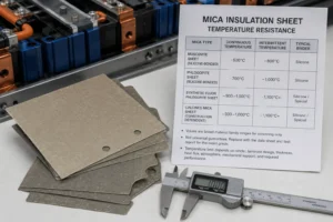
Mica Insulation Sheet Temperature Resistance: Quick Guide
| Mica Construction | Typical Continuous | Typical Short-Term | Primary EV Use | Critical Caveat |
| Silicone-bonded muscovite | ~500°C | ~800°C | Busbars and HV insulation | Binder, film, and adhesive may limit |
| Silicone-bonded phlogopite | ~700°C | ~1,000°C | Vent, lid, and fire barriers | Grade and duration must be verified |
| Synthetic or calcined mica | ~900-1,000°C | Higher, product-specific | Extreme thermal applications | Cost and binder dependence |
| Product-specific mica tape | Use TDS rating | 1,000°C torch example | Local wrap and vent protection | Torch temperature is not service rating |
Mica Insulation Sheet Temperature Resistance: The Direct Answer
For EV battery engineering, a useful initial screening range is approximately 500°C continuous and 800°C intermittent for many silicone-bonded muscovite sheets, and approximately 700°C continuous and 1,000°C intermittent for many silicone-bonded phlogopite sheets. Current commercial guidance also lists synthetic fluor phlogopite and some calcined mica constructions near 900-1,000°C continuous service, depending strongly on the binder and laminate design.
These values are not universal guarantees. They describe broad material families and must be replaced by the data sheet and test report for the exact grade. A rigid phlogopite board, a flexible mica paper, a glass-backed tape, and an adhesive-backed EV barrier can all use the word ‘mica’ while having different temperature limits.
The most important specification question is not simply ‘What temperature can mica withstand?’ It is: ‘At what temperature, for how long, under what heat flux and atmosphere, with what mechanical support, while retaining which required property?’
Mica Insulation Sheet Temperature Resistance at a Glance
The following ranges are practical sourcing and prototype-screening values drawn from current commercial mica guidance. They should not be copied into an automotive drawing without confirming the exact construction and test method.
Muscovite is often selected when high dielectric performance and dimensional control are the primary requirements. Phlogopite generally offers higher heat resistance and is therefore common in flame-facing and severe thermal locations. Synthetic and calcined mica constructions can extend the temperature range but may add cost, sourcing complexity, stiffness, or binder limitations.
A product-specific example is Saint-Gobain CHR FR1000 mica tape, whose current technical data sheet reports resistance to a flame torch up to 1,000°C. That claim belongs to the exact mica backing and flame-retardant silicone adhesive construction; it should not be generalized to every mica sheet.
What Does ‘Withstand Temperature’ Actually Mean?
Continuous service temperature describes prolonged exposure while the material retains specified electrical, mechanical, and dimensional properties. This is the relevant limit for components located near routine heat sources or continuously warm conductors.
Intermittent or peak temperature describes a shorter event. The material may remain physically present, but long-term aging, color, flexibility, binder strength, dielectric performance, and adhesion may be affected. The allowed duration must be stated.
Flame or torch temperature identifies the heat-source temperature, not necessarily the sheet’s uniform internal temperature. A thin mica tape may face a 1,000°C flame for a defined time while the cold side remains cooler. Torch distance, flame power, specimen support, exposure area, and failure definition control the result.
Mineral stability describes the mica crystal itself. It does not prove that a bonded commercial sheet, film laminate, adhesive, or foam composite will retain its production shape and function at the same temperature.
Thermal class is another separate concept. IEC 60085 assigns thermal classes to electrical insulating materials and systems based on long-term thermal endurance. A mica-based system can have a Class H or other system rating that is far lower than the temperature the mineral can survive during a short fire event.
Why Raw Mica and a Finished Mica Sheet Have Different Limits
Raw mica is an inorganic layered silicate mineral. Commercial sheets, however, usually consist of mica paper or mica splitting’s held together by silicone, epoxy, or another resin. They may also include glass fabric, polyester film, polyimide film, pressure-sensitive adhesive, ink, foam, or a release liner.
The organic portion is often the first temperature-limiting element. The binder may lose strength or decompose while the mica flakes remain intact. The sheet can then become brittle, powdery, warped, or delaminated. An adhesive can release the barrier from the pack lid before the mica itself is damaged.
This explains why mineral-level claims above 1,000°C and commercial continuous ratings around 500-700°C can both be technically correct. They describe different constructions, durations, and acceptance criteria.
For EV battery parts, the qualification unit should be the exact die-cut laminate, including the approved mica source, binder, reinforcement, adhesive, surface film, thickness, edge condition, and mounting method.
Muscovite Mica Insulation Sheet Temperature Resistance
Muscovite is widely used in electrical insulation because it combines strong dielectric properties with dimensional stability and good processability. Current commercial guidance commonly places silicone-bonded muscovite sheet near 500°C for continuous service and near 800°C for intermittent exposure.
Muscovite is a strong candidate for busbar barriers, high-voltage junction boxes, terminal shields, contactor insulation, module-frame isolation, and other locations where electrical performance is more important than direct long-duration flame exposure.
The grade still needs application testing. A thin muscovite sheet may survive the temperature but crack at a tight bend or around a punched terminal window. A polyester-backed version may be limited by the film. An acrylic adhesive may release far below the mica’s thermal capability.
When the location faces a severe vent jet or repeated high-temperature exposure, a phlogopite or specialized composite may provide a larger thermal margin.
Phlogopite Mica Insulation Sheet Temperature Resistance
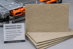
Phlogopite is generally selected for higher-temperature applications. Current commercial material guidance commonly identifies approximately 700°C continuous service and intermittent exposure approaching 1,000°C for silicone-bonded phlogopite constructions.
This makes phlogopite a common candidate for EV pack lids, module fire partitions, vent corridors, high-temperature busbar shields, and flame-facing layers in thermal-runaway barriers.
Higher temperature capability does not automatically mean better overall performance. Phlogopite can have different tensile, flexural, dielectric, and die-cut characteristics from muscovite. The best grade depends on whether the part must be rigid, flexible, folded, adhesive-backed, puncture-resistant, or combined with foam.
The supplier should report retained integrity and dielectric performance after heat exposure. A sheet that remains visible but separates into weak layers may not protect the next cell or high-voltage component.
Synthetic and Calcined Mica Temperature Capability
Synthetic fluor phlogopite and some calcined mica constructions can provide higher purity, more consistent composition, and temperature capability around 900-1,000°C continuous service in current commercial guidance. Short-term values may be higher, depending on the mineral, binder, and test method.
These materials can be useful where the design requires extreme thermal stability, low ionic contamination, controlled dielectric properties, or demanding aerospace and fire-resistant electrical performance.
They are not automatically the most cost-effective EV solution. Availability, minimum order quantity, mechanical flexibility, lamination behavior, die-cut yield, and validation history may favor a conventional phlogopite construction.
Use specialized grades only when the system test shows that the additional performance is necessary. A lower-cost grade with better support, vent routing, or hybrid insulation may outperform an expensive mineral used in a poor geometry.
Continuous Temperature vs Thermal-Runaway Peak Temperature
An EV battery’s normal operating environment and a thermal-runaway event create fundamentally different requirements. Normal service focuses on years of thermal aging, dielectric reliability, humidity, vibration, and adhesive durability. Thermal runaway is a short, high-intensity event involving radiation, flame, hot gas, pressure, particles, and possible electrical arcing.
A sheet rated for 500°C continuous service has a different evidence base from a tape that survives a 1,000°C flame torch for a short period. Neither statement alone predicts module propagation time.
For routine service, verify thermal class, long-term aging, retained dielectric properties, mechanical strength, and adhesion. For thermal runaway, verify burn-through time, cold-side temperature, erosion, edge penetration, delamination, attachment, and electrical separation.
Do not specify one ‘maximum temperature’ to cover both conditions. Write separate continuous, intermittent, and abuse-event requirements.
Why Thermal Class Is Not the Same as Peak Temperature
IEC 60085 distinguishes thermal classes for electrical insulating materials and electrical insulation systems. These classes are based on thermal endurance and aging, not brief survival under an extreme flame.
A mica laminate may contain a polyester film, epoxy binder, or pressure-sensitive adhesive that determines the long-term thermal class. The mineral may remain stable at several hundred degrees above that classification, but the completed electrical system may not retain its required life or dielectric properties.
This distinction prevents a common sourcing error: comparing a 180°C thermal-class statement with a 1,000°C torch statement as though they were competing values. They answer different engineering questions.
For EV busbars and junctions, long-term electrical endurance may be the priority. For a pack-lid fire barrier, short-term heat and flame integrity may dominate. Some parts need both.
How Binder Chemistry Controls Temperature Resistance
The binder holds mica paper or flakes in a usable sheet. Silicone resins are commonly selected for higher-temperature flexibility, while epoxy systems can create rigid, mechanically strong boards. Other organic or inorganic systems may be used for specialized products.
A higher binder content can improve toughness, cutting yield, and edge strength, but it adds more organic material that can soften, smoke, char, or decompose. Too little binder can produce dust, weak edges, and delamination.
Ask the supplier to identify binder chemistry, nominal content, cure state, temperature limits, and change-control requirements. A material trade name without binder information is incomplete.
Post-heat inspection should determine whether the mica remains as a coherent barrier after the binder changes. For direct flame locations, a controlled nonconductive residue may be acceptable if the part remains over the protected surface; uncontrolled separation is not.
How Adhesive Limits Mica Insulation Sheet Temperature Resistance
Adhesive-backed mica simplifies assembly, but the adhesive often has a much lower long-term temperature capability than the mica. Acrylic, silicone, rubber, and structural adhesives each have different heat, flame, humidity, and chemical behavior.
The adhesive does not always need to retain its original peel strength during the complete thermal-runaway event. It may only need to hold the part during manufacturing and normal vehicle life if mechanical compression or clips retain the mica during abuse. That requirement must be explicit.
Full-face adhesive adds a continuous organic layer and can change heat transfer, smoke, and flame behavior. Selective adhesive zones can reduce polymer content and thermal bridging while maintaining alignment.
Test peel, shear, creep, liner release, and post-aging adhesion on the actual substrate. Also verify whether the mica remains in position after the adhesive chars or releases under fire exposure.
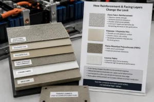
How Reinforcement and Facing Layers Change the Limit
Glass fabric can improve tensile strength, puncture resistance, dimensional stability, and post-binder support. It is common in mica tapes and laminates intended for demanding electrical or fire applications.
Polyester or polyimide films can provide a smooth dielectric surface and cleaner die cutting, but their temperature behavior may become the limiting factor. Flame-retardant polycarbonate can add structural strength and puncture resistance, while a ceramic fabric can improve direct-flame durability.
Every facing changes the effective temperature response. Differential thermal expansion can create curl or delamination. A low-temperature film may retract and expose the mica edge. A heavy glass reinforcement can increase stiffness and heat conduction.
The construction should be tested as a complete laminate, not approved by adding separate data-sheet ratings for each layer.
Why Thickness Changes Mica Temperature Performance
Thickness affects more than dielectric voltage. A thicker mica sheet generally takes longer to heat through, resists particle erosion for more time, and provides additional material before burn-through. It may also span a larger unsupported gap.
However, thickness does not change the intrinsic decomposition temperature of the binder or film. A thick sheet with a weak resin can still delaminate, while a thinner reinforced sheet may remain coherent.
The relevant value is the minimum finished thickness after grinding, lamination, die cutting, handling, and assembly. Local crushing at edges, fasteners, or ribs can create weak zones.
Qualification samples should represent the thinnest allowed production part, the largest unsupported span, and the worst cutout geometry. Do not test a thick flat coupon and apply the result to a thinner production shape.
Heat Flux, Duration, Atmosphere, and Support Matter
Temperature alone does not describe thermal severity. A 1,000°C low-power flame applied to a small supported area may be less damaging than a lower-temperature high-heat-flux jet carrying particles across an unsupported edge.
Exposure time controls how deeply heat penetrates. A sheet that survives five seconds may fail after sixty seconds. Radiation, convection, direct flame contact, and conductive contact with hot metal create different thermal gradients.
Atmosphere also matters. Air, inert gas, reducing gas, electrolyte vapor, and combustion products can affect binders, adhesives, and surface conductivity. Pressure and high-speed particles can erode the barrier mechanically.
Support can determine success. A mica sheet bonded to a rigid lid behaves differently from the same sheet spanning a cavity. Mechanical clips, ribs, or laminate reinforcement may keep the mineral layer in position after the binder degrades.
Mica Insulation Sheet Temperature Resistance by EV Pack Location
Busbar and junction-box insulation usually needs strong long-term dielectric performance, dimensional stability, puncture resistance, and moderate heat endurance. Muscovite or a mica-polymer laminate may be efficient when direct flame exposure is limited.
Pack-lid and vent-corridor barriers face short, severe heat, flame, and particle exposure. Phlogopite, synthetic mica, glass reinforcement, or a mica-aerogel composite may be more appropriate.
Module walls and pack perimeters need both high-temperature integrity and mechanical support over a broad area. Rigid board thickness, mounting, holes, and edge coverage can be more important than the highest nominal mineral temperature.
Cell-to-cell barriers require careful comparison with aerogel. Mica can protect against flame and electrical contact, but aerogel generally provides greater thermal resistance per millimeter. A hybrid barrier is often more efficient than simply increasing mica thickness.
Service disconnects, fuses, and contactor areas may require arc, flame, and dielectric protection. The test should reproduce the electrical fault as well as the temperature.
How Mica Responds During EV Battery Thermal Runaway
Thermal runaway can expose the barrier to rapidly changing temperatures, flame, gas pressure, electrolyte, conductive particles, and hot metal. The sheet’s purpose is often to remain a separating layer long enough to protect an adjacent cell, maintain a high-voltage boundary, or delay pack-cover damage.
The mica need not remain cosmetically unchanged. Discoloration, binder charring, or loss of adhesive may be acceptable if the barrier retains coverage, electrical separation, and the project-defined cold-side temperature or burn-through performance.
A mica sheet cannot independently guarantee non-propagation. Hot gas can flow around edges, busbars and cooling plates can bypass the insulation, and uncovered openings can become line-of-sight flame paths.
Representative module and pack testing is required. UN Regulation No. 100 evaluates thermal-propagation safety at the rechargeable energy storage system or vehicle level; it does not assign compliance to a mica coupon.
Mica vs Aerogel, PC, and Silicone Foam at High Temperature
Mica provides high-temperature structural and dielectric integrity. Aerogel provides very low thermal conductivity and strong heat-transfer delay in thin gaps. Flame-retardant polycarbonate provides puncture-resistant structural dielectric coverage but has a lower direct-flame capability than mica. Silicone foam provides compression, swelling, vibration, and sealing functions.
A pack lid may use mica as the flame-facing layer and aerogel behind it to reduce cold-side temperature. A busbar part may use mica with PC for shape and puncture protection. A cell pad may use mica with silicone foam to combine fire resistance and pressure management.
The weakest layer still controls the system. A 1,000°C mica facing does not make an acrylic adhesive or PC carrier a 1,000°C component. Layer order, attachment, edge design, and mechanical support determine whether the high-temperature mica remains useful.
Use the simplest laminate that passes the relevant electrical, mechanical, and abuse tests. Added layers increase tolerance, cost, and change-control risk.
How to Test Mica Insulation Sheet Temperature Resistance
Level 1 material testing should measure thickness, areal mass, binder content, dimensional change, mass loss, dielectric strength, insulation resistance, flexural or tensile strength, and thermal aging. IEC 60371 provides definitions, general requirements, and test methods for built-up mica materials and mica paper.
Level 2 finished-part testing should evaluate cut edges, holes, bends, flatness, delamination, adhesive peel, liner release, and retained properties after heat and humidity conditioning.
Level 3 thermal testing can use ovens, furnaces, thermogravimetric analysis, heat-flux exposure, flame torches, burners, hot-gas jets, and particle impingement. The report must state temperature, heat flux where available, duration, distance, support, atmosphere, and failure criterion.
Level 4 representative module testing should use the real cell chemistry, capacity, state of charge, vent direction, electrical connections, cooling system, compression, and enclosure geometry.
Level 5 pack or vehicle validation should confirm warning, controlled venting, electrical isolation, structural response, external hazards, and post-event condition.
How to Write a Temperature Specification for Mica
Avoid a requirement such as ‘mica shall withstand 1,000°C.’ It does not define exposure time, heat source, retained property, sheet construction, or test method.
A better normal-service requirement identifies the exact laminate and states a continuous-use temperature or thermal class, aging duration, and retained dielectric and mechanical properties.
A better abuse-event requirement states the flame, hot-side temperature or heat flux, duration, support condition, minimum thickness, cold-side temperature limit, burn-through criterion, edge condition, attachment, and post-test electrical separation.
The bill of materials should identify mica type, binder, reinforcement, film, adhesive, thickness, approved manufacturer, and approved converter. Any change to these elements should receive engineering review and, where necessary, repeat validation.
Separate the material specification from the system acceptance criterion. The material report qualifies the part; the module or pack test qualifies the application.
Common Temperature-Rating Mistakes
The first mistake is quoting the mineral temperature as the finished sheet rating. The binder, adhesive, film, and support usually determine the practical limit.
The second mistake is mixing continuous, intermittent, and torch temperatures. A product can have three valid but different numbers.
The third mistake is assuming a higher temperature rating always produces a safer pack. Thermal conductivity, thickness, heat bypasses, vent routing, electrical geometry, and attachment may dominate.
The fourth mistake is treating UL 94 V-0 as proof of 1,000°C fire protection. UL 94 uses small-scale flame tests for specified polymeric materials; it is not a battery vent-jet or pack test.
The fifth mistake is testing a flat raw sheet while producing an adhesive-backed die-cut part with holes, narrow edges, and unsupported spans.
The sixth mistake is approving a supplier substitution without comparing mica source, binder percentage, reinforcement, thickness, and high-temperature test evidence.
DFM for High-Temperature Die-Cut Mica Parts
Mica can crack, chip, delaminate, or release particles during cutting. High-temperature performance is compromised when a terminal cutout or narrow bridge contains an edge crack.
The drawing should define minimum web widths, hole-to-edge distance, internal radii, unsupported spans, bend zones, adhesive pattern, liner split, pull tabs, flatness, cleanliness, and packaging.
Flatbed, rotary, CNC, stamping, and other cutting methods may be used depending on grade, thickness, reinforcement, feature complexity, and annual volume. Tool sharpness, clearance, support liner, cutting pressure, and dust extraction should be process-controlled.
A DFM review should also examine thermal coverage. A cutout required for assembly may expose the highest heat-flux location. A small geometry change can provide more protection than a higher-temperature raw material.
Prototype the exact laminate and perform assembly, heat, flame, vibration, and electrical tests before production tooling is frozen.
Industry Insight: Temperature Claims Are Becoming Application-Specific
EV buyers are moving away from generic statements such as ‘mica withstands 1,000°C.’ They increasingly request burn-through time, cold-side temperature, retained dielectric integrity, post-flame attachment, edge durability, and data from the actual installed laminate.
This change reflects higher pack integration, large-format cells, fast charging, and evolving system-level thermal-propagation requirements. Thin barriers must provide fire, electrical, mechanical, and assembly functions simultaneously.
The market is also moving toward multifunctional structures: mica plus aerogel for flame and thermal resistance, mica plus silicone foam for fire protection and cell swelling, and mica plus PC for high-temperature and structural dielectric coverage.
For a die-cut manufacturer, the competitive value is not the highest temperature number. It is the ability to translate a validated material into a clean, traceable, dimensionally controlled part that remains over the correct location during the event.
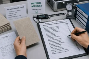
How to Audit a Mica Insulation Supplier
Request the exact material data sheet, temperature definitions, test reports, mica type, binder, reinforcement, thickness range, approved source, and shelf-life information.
Separate typical values from guaranteed specification limits. Confirm whether the temperature claim belongs to the raw mineral, bare sheet, tape, adhesive-backed laminate, or completed die-cut part.
Audit incoming inspection, controlled storage, lamination, die cutting, dust control, edge inspection, thermal and electrical test capability, packaging, lot traceability, nonconformance control, and engineering-change notification.
Automotive programs should review IATF 16949 or applicable quality-system evidence, APQP support, PPAP capability, PFMEA, control plans, measurement-system analysis, capability studies, and capacity.
Evaluate engineering response as well as equipment. A qualified converter should question an undefined 1,000°C requirement, identify the likely weak layer, and propose a testable finished construction.
RFQ Checklist for Mica Insulation Sheet Temperature Resistance
Provide the exact application location, pack voltage, cell format, vent direction, expected hot-side exposure, continuous operating environment, abuse-event duration, available thickness, substrate, support spacing, mounting method, and annual volume.
Send the CAD or PDF drawing with critical dimensions, tolerances, holes, radii, bends, edge distances, adhesive zones, liner split, pull tabs, orientation, cleanliness, and packaging requirements.
Define the retained function: no burn-through, maximum cold-side temperature, minimum dielectric strength after exposure, dimensional stability, attachment, or a module-level propagation criterion.
State prototype quantity, planned thermal and electrical test methods, PPAP level, production timing, and any current cracking, delamination, adhesive, burn-through, or heat-transfer problem.
How Boost Insulation Supports High-Temperature Mica Parts
Boost Insulation’s current public website describes an IATF 16949- and ISO 9001-certified China manufacturer focused on EV battery insulation and precision die cutting. It promotes DFM support, in-house tooling, controlled-environment lamination and die cutting, rapid samples, APQP and PPAP support, and lot-to-lot traceability.
The site states suitable precision parts can reach tight dimensional tolerances and that custom samples can be supplied within 48 hours. Its product and process portfolio includes mica, flame-retardant polycarbonate, aerogel, silicone materials, films, adhesives, lamination, slitting, CNC processing, and rotary die cutting.
For a temperature-critical mica project, engineering support can include muscovite-versus-phlogopite screening, binder and laminate review, thickness selection, adhesive zoning, glass or PC reinforcement, mica-aerogel and mica-foam stack design, edge DFM, prototype conversion, inspection planning, and test-sample preparation.
A productive inquiry should include the drawing, temperature definition, exposure duration, flame or heat-flux method, retained-property target, electrical requirement, annual volume, and validation schedule.
| Need a high-temperature mica barrier designed for a real EV exposure?
Send Boost Insulation your busbar, module, pack-cover, cell-interface, or vent-barrier drawing together with the continuous temperature, peak or flame exposure, duration, retained-property target, voltage, thickness, adhesive and reinforcement needs, annual volume, and validation schedule. Visit boostinsulation.com to upload a drawing or request a quote |
Frequently Asked Questions
Can every mica insulation sheet withstand 1,000°C?
No. Some phlogopite, synthetic, calcined, or product-specific flame-barrier constructions can tolerate exposure near 1,000°C, but many bonded muscovite sheets have lower continuous ratings. The binder, adhesive, duration, and test method control the finished part.
What is the continuous temperature of muscovite mica sheet?
A common commercial screening value for silicone-bonded muscovite is about 500°C continuous service, with intermittent exposure around 800°C. Confirm the exact supplier grade and retained-property requirements.
What is the continuous temperature of phlogopite mica sheet?
A common commercial screening value is about 700°C continuous service, with intermittent exposure approaching 1,000°C. The exact value depends on purity, binder, reinforcement, thickness, and construction.
Can mica survive a 1,000°C battery flame?
A correctly designed mica barrier may survive a short 1,000°C-class flame exposure, and some product-specific tapes are tested at that flame temperature. Survival time, heat flux, particles, support, edges, and retained function must be validated.
Does thicker mica withstand a higher temperature?
Thickness can improve burn-through time, thermal resistance, stiffness, and erosion resistance, but it does not raise the decomposition temperature of the binder or adhesive. Test the minimum finished thickness.
Why is the thermal class lower than mica’s peak temperature?
Thermal class reflects long-term aging and retained properties of the material or insulation system. Peak or torch ratings describe short exposure. They answer different engineering questions.
Is phlogopite always better than muscovite for EV batteries?
No. Phlogopite usually provides higher temperature capability, while muscovite often offers strong dielectric and mechanical performance. The location, voltage, flame exposure, geometry, and cost determine the best grade.
What data is needed for a custom high-temperature mica part?
Provide the CAD or PDF drawing, continuous and peak exposure, duration, heat-flux or flame method, required retained properties, voltage, thickness, adhesive and reinforcement needs, volume, and validation plan.
Technical References
- Axim Mica. Mica Sheet Material Specifications, 2026: commercial guidance for continuous and intermittent temperature ranges of muscovite, phlogopite, synthetic, and calcined mica constructions. Source
- Axim Mica. Flexible Mica Sheets: Properties, Applications, and Industrial Uses, 2026. Source
- Saint-Gobain Tape Solutions. CHR FR1000 Mica Tape Technical Data Sheet, August 2025: product-specific resistance to a flame torch up to 1,000°C. Source
- IEC. IEC 60085:2007, Electrical insulation – Thermal evaluation and designation. Source
- IEC. IEC 60371-1:2003, Specification for insulating materials based on mica – Definitions and general requirements. Source
- IEC. IEC 60371-2:2004, Specification for insulating materials based on mica – Methods of test. Source
- IEC. IEC 60371-3-2:2005, Mica paper used for built-up mica materials. Source
- UL. Understanding UL 94 Certifications and Limitations: UL 94 is a small-scale flammability test and is not an EV battery vent-jet or pack-level test. Source
- UNECE. UN Regulation No. 100, Revision 3, rechargeable electrical energy storage system requirements. Source
- UNECE. Proposal for the 05 Series of Amendments to UN Regulation No. 100, including improved thermal-propagation requirements. Source
- Boost Insulation. EV battery insulation, mica and film conversion, DFM, rapid prototyping, APQP, PPAP, and lot-traceability capabilities. Source
Related Posts:
How Do You Choose Battery Aerogel Insulation for EVs?
Why Do EV Battery Packs Use a Mica Insulation Sheet?
Why Choose a China Factory for Die-Cut Insulation?
Why EV Battery Modules Need Specialized Insulation?
Is Flame Retardant Polycarbonate Better Than Acrylic?
What Thermal Conductivity Should EV Aerogel Insulation Have?
 betty wong