
How Does PC Insulation Resist Puncture in EV Batteries?
Table of Contents
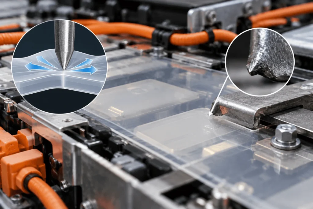
A PC insulation sheet can look electrically robust on a datasheet, but what happens when a sharp metal burr, fastener, bracket, or concentrated load presses against it through years of vibration and thermal cycling? In an EV battery, mechanical damage can become an electrical problem long before a visible short circuit occurs. The dielectric barrier is reliable only while the physical insulation remains intact, correctly located, and protected from local stresses that can cut, crack, thin, or penetrate it.
PC can resist puncture in EV battery assemblies because a properly selected polycarbonate grade combines toughness, rigidity, and thickness to spread or absorb localized mechanical loading before a sharp feature penetrates the dielectric barrier. However, actual PC puncture resistance in EV batteries is grade-, thickness-, geometry-, load-, temperature-, and test-method-dependent. Burr shape, tip radius, fasteners, holes, narrow webs, vibration, thermal cycling, adhesives, and assembly tolerances can all change the failure risk. For engineering decisions, representative testing of the finished die-cut part and installed assembly is more meaningful than a raw-sheet impact value alone.
Key Takeaways
- Puncture resistance is not the same property as impact strength, tensile strength, or hardness; contact geometry and support conditions strongly influence penetration behavior.
- The most dangerous locations are often mechanical interfaces—metal burrs, fasteners, holes, slots, brackets, narrow webs, and misaligned components—not the open center of the PC sheet.
- Increasing thickness can improve mechanical margin in many constructions, but it does not correct a sharp burr, poor load path, inadequate edge radius, or an unstable assembly.
- A punctured or deeply damaged PC part may reduce dielectric thickness, expose conductive hardware, or shorten separation paths, increasing electrical insulation risk without guaranteeing an immediate short circuit.
- Validation should progress from raw material to finished part to representative assembly, including mechanical/environmental exposure followed by electrical checks where required.
Why Does Puncture Resistance Matter in EV Batteries?
Battery insulation is usually discussed through dielectric strength, insulation resistance, creepage, and clearance. Those measures assume the physical dielectric barrier remains present where the design expects it. A burr, fastener, or hard protrusion can create a different failure path: localized mechanical stress damages the polymer first, then the damaged geometry reduces electrical isolation margin.
The event may be subtle. A sheet can remain installed while indentation, rubbing, or local thinning develops. The engineering objective is therefore to preserve barrier integrity over the mechanical and environmental life of the assembly—not simply to select a plastic with a high datasheet strength.
What Does Puncture Resistance Actually Mean?
Puncture is penetration caused by localized contact. Damage may begin as indentation or yielding and progress to cracking, cutting, tearing, or full penetration. A rounded probe, stamped-metal burr, and screw edge create different stress fields even at similar nominal force.
Puncture resistance is therefore not interchangeable with impact strength, tensile strength, or hardness. ISO 6603-2 defines an instrumented puncture-impact method for rigid plastics under controlled specimen and striker conditions. Such data are useful for screening, but an EV design still has to validate its actual contact shape, support, thickness, temperature, and loading history.
Why Can Polycarbonate Resist Mechanical Penetration?
Polycarbonate is useful in puncture-prone battery locations because many grades combine toughness with enough rigidity to remain a defined structural sheet. A suitable PC construction can deform and spread local stress before a sharp feature completely penetrates the dielectric barrier.
But ‘polycarbonate‘ is not one mechanical performance level. Grade, flame-retardant formulation, reinforcement, sheet construction, thickness, temperature, aging, and surface condition all matter. Covestro publishes grade-specific puncture-impact results that vary across Makrolon grades, illustrating why performance must stay tied to a specific material and test condition.
If a flame-retardant PC grade is required, keep flammability and puncture qualification separate. UL 94 classifications describe burning behavior under specified specimen and test conditions; they do not certify puncture resistance or mechanical durability.
What Can Puncture PC Insulation Inside an EV Battery?
Typical sources include stamped metal burrs, sharp frame edges, end plates, brackets, bolt heads, screws, washers, weld features, busbar edges where relevant, foreign debris, assembly tools, and misalignment. A broad surface may create distributed compression, while a tiny protrusion can convert the same general load into a severe point contact.
The design review should map which hard features can touch the PC at worst-case tolerance and which can move under vibration or swelling. That contact map often reveals risks that a simple 2D insulation outline misses.
Why Are Metal Burrs Especially Dangerous?
A metal burr combines a hard material with a very small contact area. The resulting local stress can be far higher than the average pressure in the surrounding structure: small contact area → high local stress → indentation or cutting → reduced dielectric thickness → possible penetration.
Thickness is only one control. Deburring, increasing edge radius, changing the load path, improving alignment, or preventing contact can be more effective. The insulation and metal part should be reviewed together rather than asking the plastic alone to compensate for uncontrolled edge quality.
How Do Fasteners Create Puncture Risk?
Bolt heads, screws, washers, and related hardware are loaded interfaces, not neutral CAD cutouts. Clamp force, hole misalignment, washer geometry, vibration, and thermal expansion can concentrate pressure at one side of the insulation.
Review hole diameter, hole-to-edge distance, washer footprint, support, fastener load or torque where relevant, metal burr condition, and tolerance stack-up. If PC is trapped between hard parts, local thinning or notching can become the starting point for later damage.
Point Load vs. Distributed Compression
Force alone does not describe puncture risk. A broad end plate can spread load across a large area, while a small protrusion concentrates it into a tiny footprint. Contact radius, local support, and bending freedom determine whether PC mainly compresses, bends, yields, cracks, or is penetrated.
In battery modules, cell swelling, bracket distortion, fastener preload, uneven surfaces, and tolerance accumulation can redirect nominally distributed compression into local contacts. If compliance is needed to absorb tolerance, a foam or elastomeric layer may be assigned that function instead of asking rigid PC to act as a compression pad.
Does Thicker PC Always Resist Puncture Better?
Greater thickness can improve penetration resistance in many constructions, but it is not a universal safety rule. A sharp burr can still cut a thicker sheet, and an unsupported hole or notch can dominate the failure mode.
Thickness also changes stiffness, bendability, mass, available space, cut-process choices, tolerance stack-up, and cost. Select thickness from the combined mechanical and electrical requirement, then verify it with representative geometry rather than extrapolating a single material test.
How Do Holes, Slots, and Narrow Webs Affect Puncture Resistance?
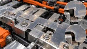
Cutouts change the load path. Holes remove support near fasteners, slots create flexible ligaments, narrow webs carry stress through small sections, and notches can initiate cracks. A cutout near an outer edge or conductor can also reduce electrical margin at the same location.
DFM should review hole-to-edge distance, web width, slot ends, registration tolerance, local compression, and assembly access. A geometry that is easy to cut can still be mechanically weak after tolerance stack-up.
Why Do Internal Corner Radii Matter?
Sharp internal corners can raise local stress where a cutout is bent, clamped, or loaded. A radius can smooth the load path and reduce crack-initiation tendency, but there is no universal minimum radius.
The appropriate geometry depends on PC grade, thickness, cutting process, installation, and load direction. DFM must also ensure the radius does not remove electrical coverage around a nearby conductive feature.
How Does Vibration Change Long-Term Puncture Risk?
A part that survives one static load can still be damaged by repeated micro-motion. Vibration can cause rubbing, fretting, fastener movement, or cyclic bending around holes and narrow webs, allowing a small mark or notch to grow.
A static puncture test therefore does not prove lifetime durability. Where the risk is credible, validation should reproduce representative mounting, vibration, and post-exposure inspection or electrical testing.
How Do Thermal Cycling and Temperature Affect Mechanical Integrity?
Temperature changes polymer behavior and also moves the surrounding stack. PC, metals, adhesives, foams, and cells expand differently, so cycling can change contact pressure, flatness, hole position, and interfacial stress.
Mechanical performance is grade- and temperature-dependent. Use the selected supplier’s data and validate the conditioned construction after relevant heat, humidity, and cycling rather than importing a generic PC temperature limit.
What Happens Electrically After PC Is Damaged?
A cut, crack, deep indentation, or penetration can reduce dielectric thickness, expose conductive hardware, shorten separation, disrupt a surface path, or allow contamination into the damaged region. These changes can reduce insulation margin even without immediate metal-to-metal contact.
The consequence depends on voltage, damage geometry, contamination, humidity, creepage and clearance, and whether PC is the only dielectric layer. IEC 60664-1 provides a general framework for clearances, creepage distances, solid insulation, and testing; the actual battery design still follows its applicable OEM and system requirements.
PC vs. PET vs. PI for Puncture-Prone Locations
Material selection should follow the failure mode. PC is often useful when a rigid or semi-rigid structural dielectric sheet must resist local mechanical abuse. PET and PI can provide excellent thin-film electrical insulation in much less space, but a flexible film should not automatically be assumed to provide the same stand-off against a sharp protrusion. Conversely, rigid PC is not always desirable where the part must wrap tightly, flex repeatedly, or tolerate very high temperatures. The comparison below is a functional starting point, not a universal ranking.
| Material | Rigidity / Form | Mechanical Protection | Electrical / Temp Role | Converting | Best Fit | Main Trade-Off |
| PC | Rigid / semi-rigid; useful load-spreading and structural support | Often favorable where sharp hardware or point contact is credible; grade and thickness dependent | Dielectric structural barrier; FR grade when required | Die-cut or CNC depending on geometry/volume | End plates, frames, covers, structural shields | More space/stiffness than thin films; polymer temperature limits |
| PET | Flexible thin film | Can protect surfaces but offers less stand-off against severe local penetration in very thin constructions | Thin dielectric barrier | Well suited to precision die cutting | Wrapped or flat insulation where thinness and flexibility dominate | Mechanical protection depends strongly on thickness/support |
| PI | Flexible high-temperature film | Thin-film puncture behavior remains geometry/thickness dependent | High-temperature dielectric film | Precision die-cuttable; handling can be delicate at thin gauges | Tight high-temperature electrical insulation zones | Cost and limited structural rigidity |
When Should PC Be Combined With Mica?
PC and mica solve different dominant problems. PC can provide tough, dimensionally defined dielectric coverage against mechanical contact; mica can retain barrier integrity under severe heat that exceeds the normal role of polymer sheets. Selected designs can use both to separate mechanical protection from high-temperature protection.
A laminate adds thickness, interfaces, adhesive decisions, and tolerance, so it should be used only when those functions are required and the finished stack is validated.
When Should PC Be Combined With Silicone Foam?
Rigid PC is not primarily a gap-management material. Silicone foam can add compliance for tolerance, vibration, or cell movement, creating a functional stack of rigid dielectric barrier plus controlled compression layer.
The benefit depends on foam stiffness, thickness, compression range, placement, and retention. Validate the combined construction at installed compression rather than relying on separate datasheets.
Can Adhesive Affect Puncture Reliability?
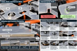
Adhesive can hold a PC insulator in position and reduce movement during assembly, but it also changes how the sheet is supported. Thickness variation, bubbles, edge lift, squeeze-out, softening, or delamination can alter local load distribution.
Raw PC properties therefore do not equal adhesive-backed component properties. Adhesive zones should be designed around contact points, holes, and assembly needs, then validated as part of the finished construction.
Common Puncture-Related Design Mistakes
- Selecting PC only from dielectric strength or flame classification.
- Treating ‘puncture resistant‘ as ‘puncture proof‘.
- Ignoring metal burrs, stamped edges, weld protrusions, or foreign debris.
- Trying to solve every risk only by increasing PC thickness.
- Ignoring point loads because the average module compression is acceptable.
- Treating a bolt hole as a neutral cutout instead of a loaded mechanical interface.
- Placing holes too close to outer edges or conductive features.
- Using sharp internal corners or unnecessarily narrow webs.
- Ignoring fastener torque, washer geometry, and tolerance-driven misalignment.
- Qualifying a room-temperature coupon but not vibration, thermal cycling, or aged conditions.
- Assuming an impact-strength value proves puncture performance.
- Validating raw sheet only, without checking the converted and installed part.
How Does Die-Cut Geometry Affect Puncture Reliability?
Precision converting does not increase intrinsic PC puncture strength. Its value is preserving the intended mechanical and electrical geometry. Hole position, slots, web width, radii, edge condition, registration, and tolerance determine where the installed part contacts hardware and carries load.
Registration error, an edge notch, or mislocated adhesive can create a weak point. Early DFM identifies these risks while the drawing is still inexpensive to change.
Die Cutting vs. CNC Cutting for PC Insulation
Die cutting and CNC cutting can both be appropriate. The process depends on geometry, thickness, part size, edge requirement, prototype stage, tooling economics, and volume. Die cutting often suits repeatable 2D production profiles; CNC can be useful for prototypes, large panels, or geometries that are inefficient to tool immediately.
Boost Insulation’s current FR-PC page lists both capabilities. An RFQ should therefore provide the drawing and volume assumptions so the conversion route can be selected during DFM rather than prescribed generically.
Why the Finished Part Matters More Than the Raw Sheet
Raw PC sheet ≠ cut part ≠ adhesive-backed part ≠ installed insulation ≠ validated battery assembly. Cutting creates edges and holes; lamination adds interfaces; handling can scratch or warp the part; installation adds clamping, alignment, and tolerance stack-up.
Procurement should control critical geometry, surface condition, cleanliness, adhesive placement, packaging, and change management—not only the material certificate. Validation specimens should resemble production parts as closely as practical.
How Should Engineers Validate Puncture Risk?
Use staged validation. Raw-material data screen grades. Finished-component tests check the actual thickness, holes, edges, adhesive zones, and dimensions. Assembly tests reproduce representative burrs, fasteners, supports, compression, and tolerance. Environmental validation adds vibration, thermal cycling, and aging where they are part of the failure path.
If mechanical damage could affect high-voltage isolation, compare electrical performance before and after exposure. Record contact geometry, fixture, loading rate, temperature, and acceptance criteria. ISO 6603-2 is useful evidence that puncture-impact behavior is test-method-specific rather than a universal material number.
Industry Insights: What This Means for Engineers and Buyers
Industry Insight 1 — Mechanical damage can precede electrical failure
A battery can lose insulation margin before any electrical fault is visible. For engineers, mechanical FMEA should be linked to the electrical safety case. For buyers, part drawings and supplier reviews should identify critical metal contacts and not only quote dielectric data.
Industry Insight 2 — Denser packaging increases interface sensitivity
As conductive structures, cells, and insulation occupy smaller gaps, small tolerance shifts can turn a nominal clearance into a contact. This increases the value of accurate cut geometry, stable installation, and early stack-up review rather than relying on more material everywhere.
Industry Insight 3 — Better metal edges can outperform extra plastic
When the failure initiator is a sharp burr, improving deburring, edge radius, or alignment can remove the stress concentration at its source. Engineers should optimize both sides of the interface; buyers should avoid specifications that force the insulation supplier to compensate for uncontrolled metal quality.
Industry Insight 4 — Static coupon data misses lifetime interactions
A room-temperature flat-sheet puncture value cannot reproduce vibration, thermal cycling, clamp load, aging, and off-center hardware simultaneously. Qualification should therefore move toward representative finished-part and assembly tests with documented fixtures and post-exposure inspection.
Industry Insight 5 — Converting geometry is part of insulation engineering
Hole location, web width, internal radii, edge quality, adhesive registration, and dimensional repeatability influence where mechanical stress is applied. Involving the converter during DFM can reduce avoidable weak points before tooling and validation lock the design.
Common Puncture Risks in EV Battery PC Insulation
The table below translates typical mechanical contacts into insulation effects and design actions. It is intended as an FMEA-style starting point; actual severity and controls depend on the battery architecture.
| Risk Source | Mechanical Mechanism | Possible Insulation Effect | Engineering Consideration |
| Metal burr | Sharp tip concentrates load | Indentation, cut, or penetration; reduced dielectric thickness | Deburr/radius metal; review contact at worst-case tolerance |
| Sharp stamped edge | Line or point contact under clamp/load | Groove, notch, crack initiation | Edge finishing, protective geometry, local support |
| Bolt / screw | Clamp load plus off-center contact | Hole-edge damage or local puncture | Control hole position, torque/load, washer geometry |
| Washer | High pressure around annular footprint | Creep, thinning, edge cutting | Increase support area; validate clamp stack |
| Point load / protrusion | Small contact area | Local yielding or full penetration | Remove protrusion, spread load, add protective layer |
| Hole / slot | Removes material and redirects stress | Crack initiation, narrow ligament failure | DFM hole-to-edge distance and slot-end radii |
| Narrow web | High load carried by small section | Tear, crack, distortion | Increase web where function permits; validate tolerance |
| Sharp internal corner | Stress concentration | Crack initiation under bending or clamp load | Use application-specific radius; review cut process |
| Misalignment | Hardware contacts unintended region | Edge loading, exposed metal, local wear | Tolerance stack-up and assembly poka-yoke |
| Vibration | Repeated micro-motion and rubbing | Fretting, groove growth, crack propagation | Representative vibration with installed contact geometry |
| Thermal cycling | Differential expansion and repeated movement | Warpage, contact shift, crack growth | Cycle complete stack and inspect critical interfaces |
| Foreign debris | Hard particle creates point load | Indentation or penetration | Cleanliness controls and protective packaging |
| Adhesive interface | Softening, bubbles, uneven support, delamination | Changed load distribution or part movement | Validate adhesive-backed construction, not raw PC alone |
Engineering Checklist for Puncture-Resistant PC Insulation
- Application location and protected conductive surfaces
- Specific PC / FR-PC grade and supplier datasheet
- Required flame classification, if applicable, at the relevant thickness
- PC thickness and overall part size
- System / working voltage and electrical insulation requirement
- Metal interface material and surface condition
- Burr condition, sharp edges, welds, or protrusions
- Minimum practical edge radius on contacting hardware
- Known point-load locations and support conditions
- Fastener locations, washer geometry, and torque/load where relevant
- Hole, slot, notch, and narrow-web geometry
- Compression path and cell swelling / stack movement
- Vehicle vibration and possible micro-motion
- Thermal-cycling range and expected differential movement
- Operating and peak temperatures for the selected PC grade
- Adhesive, lamination, liner, or protective-film requirements
- Available installation space and tolerance stack-up
- Assembly method, automation constraints, and handling risk
- Representative mechanical validation method and acceptance criteria
- Electrical checks required after mechanical/environmental exposure
What to Send With a PC Battery Insulation RFQ
- PDF, DXF, and/or STEP drawing
- Application location and short description of the failure risk
- Specified PC / FR-PC grade, if already selected
- Flame-retardancy requirement and applicable test/classification
- Thickness and overall part dimensions
- Critical hole, slot, notch, and narrow-web geometry
- Dimensional tolerances and registration requirements
- Metal interface drawing or photos, including sharp edges and burr condition
- Fastener locations, washer geometry, and clamp/torque information where relevant
- Expected compression, point load, or contact condition
- System voltage and electrical insulation requirements
- Operating temperature, thermal cycling, vibration, and aging requirements
- Adhesive / lamination / liner requirements
- Prototype quantity and expected annual volume
- Validation requirements and any current failure mode
- PPAP / documentation requirements where applicable
- Packaging, cleanliness, surface-protection, and traceability requirements
From Material Selection to an Assembly-Ready PC Insulator
For puncture-sensitive parts, sourcing only PC sheet leaves the main manufacturing risks unresolved. The production component still needs material confirmation, DFM, process selection, hole and edge control, adhesive integration where required, prototyping, inspection, packaging, and production repeatability. Boost Insulation’s website currently lists FR-PC material support, die cutting, CNC processing, lamination, adhesive integration, and prototype-to-production converting.
The supplier discussion should stay tied to the failure mode. If a burr or fastener creates the risk, review that interface instead of simply recommending more thickness. The finished part remains an input to engineering validation, not proof of pack safety.
Engineering CTA
If puncture or mechanical damage is a concern in your EV battery insulation design, send Boost Insulation the drawing, PC grade, thickness, metal contact geometry, burr or edge condition, hole and fastener locations, expected compression, system voltage, adhesive needs, prototype quantity, and annual volume. A DFM review can then focus on likely weak points—contact geometry, cutouts, local support, conversion method, and assembly tolerance—before prototype validation or production tooling.
Frequently Asked Questions
Why does puncture resistance matter in EV battery insulation?
Because the electrical barrier only works as designed while it remains physically continuous and correctly positioned. A burr, fastener, sharp bracket, or point load can thin, crack, cut, or penetrate the PC. That damage may reduce dielectric thickness, expose conductive hardware, or shorten electrical separation. It does not guarantee an immediate short circuit, but it can create a local weak point that should be evaluated within the high-voltage insulation design.
Why is polycarbonate resistant to puncture?
Many polycarbonate grades combine toughness and rigidity, allowing the sheet to deform and distribute localized load before a contacting feature penetrates it. The actual behavior is not universal. Grade, thickness, flame-retardant formulation, temperature, support condition, striker or burr geometry, loading rate, holes, and aging all matter. For that reason, impact strength or tensile strength should not be used as a substitute for a representative puncture test.
Can metal burrs puncture PC battery insulation?
Yes. A sharp metal burr can create a very small contact area and therefore a high local stress. Whether it penetrates the PC depends on burr geometry, load, PC grade and thickness, support, temperature, movement, and service history. Deburring, radiusing, changing the load path, improving alignment, or adding a protective layer may reduce risk more effectively than increasing PC thickness alone.
Does thicker PC always improve puncture resistance?
Greater thickness can improve penetration resistance in many constructions, but it is not a universal fix. A sharp feature can still cut a thicker sheet, while holes, notches, unsupported areas, vibration, or misalignment can dominate the failure. Thickness also affects stiffness, space, weight, forming, cut geometry, cost, and tolerance stack-up. Select it from the complete application and confirm it with representative testing.
How do holes and cutouts weaken PC insulation?
Holes, slots, and notches remove load-carrying material and change how stress flows through the part. A hole near an edge can leave a narrow web; a sharp slot end can become a crack-initiation site; and a misregistered fastener can load one side of a cutout. DFM should review hole-to-edge distance, local support, internal radii, registration tolerance, and the relationship between cutouts and nearby conductive hardware.
Is PC more puncture resistant than PET or PI?
PC is often selected when the design needs a more rigid structural dielectric barrier with stronger resistance to localized mechanical abuse. PET and PI are typically used as thinner flexible dielectric films and can be better where space, wrapping, or high-temperature film performance dominates. There is no universal winner: grade, thickness, support, contact geometry, temperature, and the required electrical and mechanical functions determine the best material or stack.
Can vibration damage PC insulation over time?
It can, especially when the installed part experiences repeated contact or micro-motion against hard hardware. Vibration may cause rubbing, fretting, fastener movement, cyclic bending near holes, or growth of an existing notch. A static puncture test therefore does not prove life-cycle durability. Where the risk is credible, validation should reproduce representative mounting, vibration, temperature conditioning, and post-exposure inspection or electrical testing.
How should engineers test PC insulation for puncture risk?
Start with grade-specific supplier data, then test the finished die-cut construction with representative contact geometry and support. Define the indenter, burr, fastener, or point-load shape; loading rate; temperature; thickness; fixture; and acceptance criteria. Add vibration, thermal cycling, aging, or compression where they are part of the failure path. If puncture could affect high-voltage isolation, compare electrical performance before and after the mechanical/environmental exposure.
Related Posts:
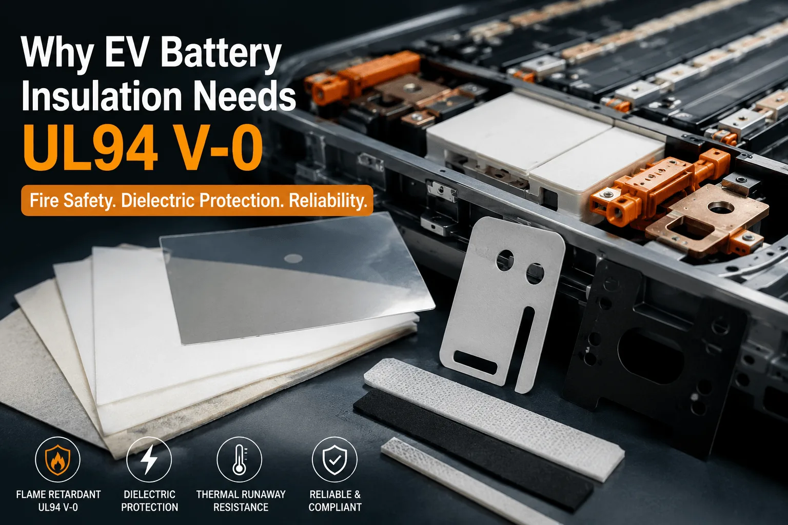
Why Does EV Battery Insulation Need UL94 V-0?
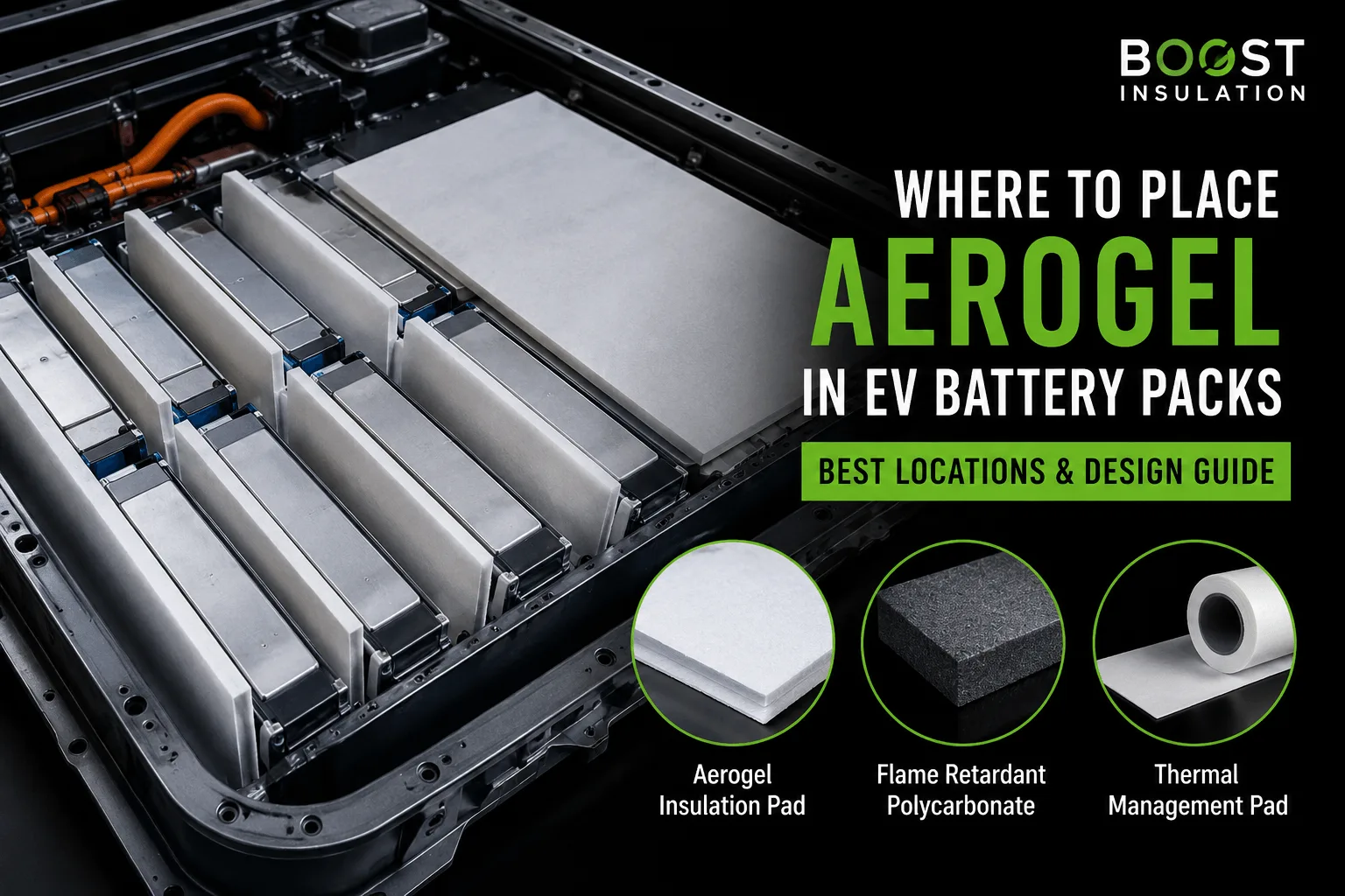
Where Is Aerogel Used Inside Modern EV Battery Packs?
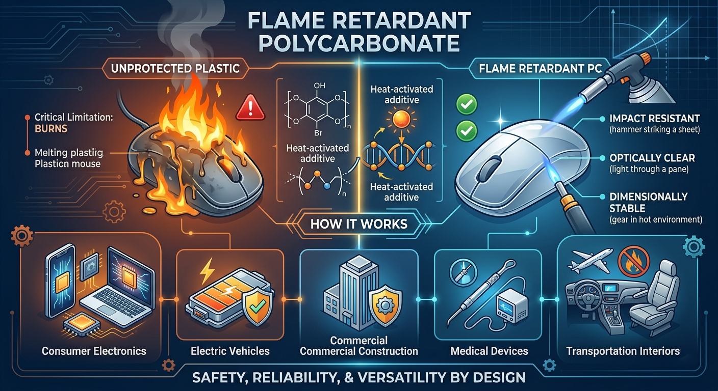
What Is Flame Retardant Polycarbonate and Why Does It Matter?
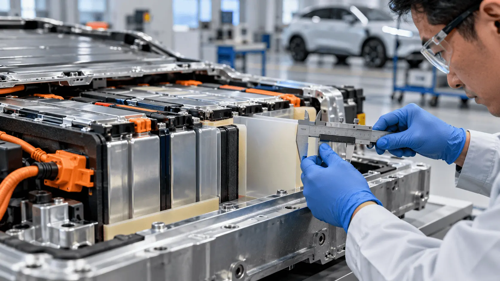
How Thick Should PC Insulation Be in EV Batteries?
How Does Silicone Foam Work With Aerogel Barriers?
What Is a Mica Insulation Sheet for EV Battery Packs?
 betty wong
