
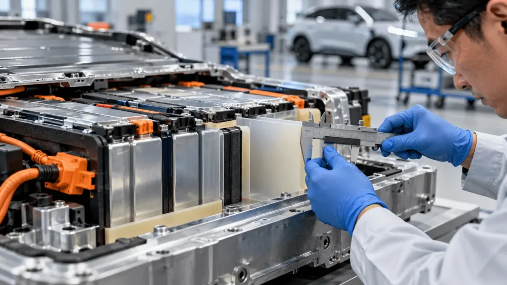
How Thick Should PC Insulation Be in EV Batteries?
Table of Contents
Should an EV battery insulation part use 0.3 mm, 0.5 mm, 0.8 mm, 1.0 mm, or an even thicker polycarbonate sheet? That question appears simple on a drawing, but choosing from a supplier thickness list alone can be misleading. The same nominal PC thickness can behave very differently depending on working voltage, dielectric requirements, puncture exposure, fasteners, unsupported area, temperature, flame rating, adhesive stack-up, tolerance, and how the finished part is installed in the battery module.
There is no universal PC insulation thickness for EV batteries. Engineers should select PC insulation thickness for EV batteries from the required electrical isolation, PC grade, puncture and mechanical risks, geometry, rigidity, available space, temperature, flame requirements, and assembly conditions. Thicker PC can increase structural stiffness and may improve penetration resistance in some constructions, but it also consumes more package space and can affect forming, cutting, tolerance stack-up, assembly, and cost. The final thickness should be confirmed on the production-intent finished component under representative electrical, mechanical, thermal, and environmental conditions.
Key Takeaways
- PC insulation thickness is an engineering selection, not a universal EV battery specification.
- Voltage is one input, but voltage alone cannot be converted into a fixed PC thickness.
- Datasheet dielectric strength is a material test result; it is not a guaranteed withstand voltage for a die-cut and installed part.
- Mechanical risks such as burrs, fasteners, point loads, holes, narrow webs, vibration, and large unsupported areas can drive thickness as strongly as electrical requirements.
- Flame-retardant classifications must be checked for the exact grade and relevant tested thickness; UL 94 V-0 is not a thermal-runaway certification.
- Nominal sheet thickness, total laminate thickness, and installed stack dimension are different specifications.
- The final selection should be validated at material, finished-part, assembly, and lifetime/environmental levels.
What Determines PC Insulation Thickness in an EV Battery?
A useful thickness decision begins with function, not with a catalog number. A PC insulator may need to separate energized hardware from conductive structure, prevent contact after vibration, cover a large end plate, resist a metal edge, remain flat enough for robotic placement, satisfy a flame requirement, or fit inside an extremely constrained gap. Each duty pushes thickness in a different direction. The design task is therefore to find a thickness that is sufficient for all required functions without consuming unnecessary space or creating avoidable manufacturing and assembly problems.
- Electrical requirement: working voltage, transients, dielectric withstand, insulation resistance, creepage, clearance, and insulation architecture.
- Mechanical protection: contact with metal structures, local compression, handling, abrasion, and the need for a robust physical barrier.
- Puncture risk: burrs, sharp edges, bolts, brackets, washers, foreign debris, or point loads that can locally damage the sheet.
- Rigidity: unsupported span, part size, form retention, flatness, and handling during assembly.
- Geometry: holes, slots, cutouts, internal corners, narrow webs, and local edge distances.
- Package space: gap to cells or structures, tolerance stack-up, adjacent components, and total laminate build.
- Temperature and flame requirement: grade-specific property retention plus any thickness-specific flammability classification.
- Manufacturing and assembly: die cutting, CNC cutting, lamination, bending, automated placement, fastener installation, and packaging.
- Validation: the production-intent part must demonstrate the required function after relevant environmental and mechanical exposures.
How Does Voltage Affect Thickness Selection?
Higher system voltage increases insulation-coordination demands, but it does not create a fixed voltage-to-PC-thickness rule. Define the local working voltage, transients, dielectric withstand, insulation architecture, creepage and clearance first, then screen candidate grade/thickness combinations. IEC 60664-1 treats solid insulation, creepage, and clearance as coordinated design elements rather than reducing the decision to sheet gauge alone.
Dielectric Strength vs. Thickness: Why kV/mm Is Not a Design Shortcut
Dielectric strength is a controlled material-test result, not a universal conversion factor. Published values depend on specimen thickness, electrodes, conditioning, temperature, humidity, voltage application, and test method; Covestro, for example, reports a value for a specific 500 micrometer Makrofol film under stated IEC 60243-1 conditions. Cut edges, holes, contamination, adhesive, compression, and installed geometry still require finished-part validation.
Does Thicker PC Always Provide Better Insulation?
Not in every engineering sense. More thickness can increase physical separation, stiffness, and mechanical margin in some constructions, but it also consumes space, adds mass and cost, reduces flexibility, changes forming/cutting behavior, and can worsen tolerance or assembly conflicts. The target is not maximum thickness; it is the minimum production thickness that reliably meets the defined electrical and mechanical requirements.
How Does Puncture Risk Affect PC Thickness?
Puncture risk often pushes a design toward a more structural PC barrier, but thickness should not mask the mechanical cause. Burrs, stamped edges, fasteners, brackets, washers, or debris can create point loads. Added gauge may help, yet deburring, edge radiusing, load spreading, better alignment, or a local protective layer can remove the risk more efficiently than thickening the whole part.
How Does Rigidity Change With Thickness?
Increasing PC thickness generally increases bending stiffness and changes handling. That can help large end-plate or structural insulators remain flat, span openings, and retain geometry, while making tight bends or conformal installation more difficult. Evaluate full part size, unsupported area, flatness, bend geometry, installation path, and support conditions rather than judging stiffness from a small coupon.
When Can Thinner PC Be Appropriate?
Thinner PC can be appropriate in a protected location with low puncture exposure, good structural support, tight packaging space, modest stiffness needs, and verified electrical/flame performance for the exact grade. The minimum local thickness after forming, lamination, compression, and production tolerance still matters; ‘thin’ is not a universal numeric category.
When May Thicker PC Be Appropriate?
Thicker PC may be justified for stronger mechanical protection, higher puncture exposure, larger unsupported spans, greater form retention, or demanding assembly handling. It is not automatically safer: added gauge can reduce air gaps, interfere with hardware, or displace other functional layers. Review the complete module stack before increasing thickness.
How Do Holes, Slots, and Cutouts Affect Thickness?
Converted geometry can be weaker than the center of the sheet. Fastener holes, slots, cutouts, narrow webs, and sharp internal corners reduce local section or concentrate stress. Review web width, hole-to-edge distance, corner radius, cutting method, and load direction during DFM; a geometry change can remove a weak point without adding thickness everywhere.
How Do Fasteners Affect Thickness Selection?
Fasteners turn a CAD opening into a loaded interface. Bolts, screws, washers, clips, and standoffs can add torque, compression, rubbing, and edge loading; misalignment can concentrate those forces. Production-intent validation should reproduce hardware, torque, alignment tolerance, and support conditions because local fastener loads may govern gauge more strongly than average module pressure.
How Does Available Space Limit PC Thickness?
Every additional fraction of thickness consumes battery-package volume and can create interference with cells, cooling, sensing, compression hardware, or adjacent insulation layers. Define the available gap and maximum installed stack, including adhesive and companion materials, then evaluate worst-case tolerance. Minimizing gauge is useful only if required electrical and mechanical margins remain validated.
How Does Temperature Affect Thickness Selection?
PC behavior is grade- and temperature-dependent. Normal operation, local hot spots, thermal cycling, and aging can change stiffness, dimensional stability, adhesion, and electrical behavior. Use grade-specific manufacturer data and test candidates in the relevant conditioned state. If severe-heat integrity is the real requirement, a separate material such as mica may be more appropriate than simply increasing PC gauge.
Does Flame Retardancy Change the Thickness Decision?
Yes. UL 94 is a small-scale flammability classification for defined specimens, and the applicable rating can depend on the exact grade and thickness. Covestro and SABIC publish PC examples with V-0 classifications at specific thicknesses rather than one universal value. Therefore verify grade + thickness together; V-0 is also not a thermal-runaway, vent-jet, or pack-level safety certification.
Does Adhesive Thickness Count Toward Battery Insulation Thickness?
Adhesive contributes to installed stack thickness but is not equivalent to PC substrate thickness. PSA has different dielectric, mechanical, thermal, aging, and compression behavior. Separate the specifications for PC thickness, adhesive thickness, laminate tolerance, and total installed stack; release liner may affect delivery/automation but normally is not part of the installed dimension.
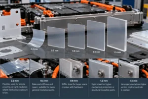
How Different PC Thicknesses Change Design Trade-Offs
The examples below are comparison points, not universal recommendations and not voltage mappings. They are useful for early DFM discussions because thickness changes several functions at the same time.
| Thickness Example | Relative Rigidity Trend | Space Consumption | Formability / Handling | Mechanical Protection | Typical Engineering Question | Validation Needed |
| 0.3 mm | Lower | Low | Flexible | Support-dependent | Is mechanical exposure low? | Electrical + puncture + FR |
| 0.5 mm | Moderate | Low-mod. | Balanced | Geometry-dependent | Enough stiffness without excess space? | Electrical + geometry + FR |
| 0.8 mm | Mod.-high | Moderate | Stiffer | Higher section | Is rigidity needed for span/hardware? | Flatness + fasteners + stack-up |
| 1.0 mm | High | Mod.-high | Rigid | Structural role possible | Will package accept added gauge? | Fit + warpage + mechanical + FR |
| 1.5 mm | High | High | Very rigid | Large section | Can interface design remove need for thickness? | Full assembly + lifetime validation |
PC vs. PET, PI, and Mica: Thickness Is Not Directly Comparable
Equal nominal thickness does not mean equal function. PC is typically a rigid or semi-rigid structural dielectric; PET is commonly a thin flexible dielectric film; PI is a thin high-temperature dielectric film; mica is used for severe-heat or flame-facing dielectric barriers. Choose material function first and thickness second, then validate any multilayer stack as an installed system.
When Should PC Be Combined With Mica?
PC and mica can be complementary when one location needs both mechanical/structural dielectric protection and severe-heat integrity. PC can provide a tougher handling surface, dimensional control, and a robust geometry around cutouts; mica can provide a high-temperature barrier where a credible abnormal event may exceed the useful role of the polymer layer. The total construction then needs individual layer thicknesses, adhesive, tolerances, assembly space, and post-exposure electrical requirements defined separately. This is a functional-layering decision, not a default recipe.
When Should PC Be Combined With Silicone Foam?
PC is not primarily a compliant gap-management material. Where the assembly also needs compression accommodation, vibration isolation, or tolerance take-up, a silicone foam or another compliant layer may be paired with the rigid PC barrier. In that case the engineer should specify installed stack thickness and compression state, not merely the nominal PC gauge. Foam compression tolerance can be much larger than sheet-gauge tolerance, so the stack should be dimensioned as a system.
Does Part Size Change the Thickness Decision?
Yes. A small insulator and a large end-plate panel made from the same gauge can behave very differently. Large parts amplify sagging, flatness, warpage, handling, hole registration, packaging, and alignment concerns. Review full-size production-intent prototypes because part size can make rigidity and dimensional stability more important than a small coupon suggests.
Thickness Tolerance Matters: Nominal Thickness Is Not Installed Stack Dimension
Nominal sheet gauge is only one contributor to the installed dimension. Sheet tolerance, adhesive, lamination, flatness, compression, adjacent-component variation, and assembly gap determine the real stack. Compare minimum and maximum conditions: the minimum may govern insulation or puncture margin, while the maximum may govern fit. RFQs should state the same thickness basis so supplier quotes remain comparable.
Common PC Thickness-Selection Mistakes
- Selecting thickness only from battery system voltage.
- Multiplying a datasheet kV/mm number by thickness and treating the result as guaranteed finished-part withstand voltage.
- Assuming thicker is always safer without checking package space, creepage/clearance, hardware, and other functional layers.
- Ignoring puncture risk from metal burrs, sharp edges, brackets, or foreign debris.
- Ignoring fastener torque, washers, local compression, and hole misalignment.
- Ignoring holes, slots, narrow webs, and internal-corner stress concentration.
- Ignoring tolerance stack-up and using nominal sheet thickness as the installed dimension.
- Ignoring temperature-dependent material behavior and thermal aging.
- Specifying UL 94 V-0 without verifying the exact grade and applicable thickness.
- Counting PSA thickness as if it provided the same structural and dielectric function as PC.
- Comparing PC, PET, PI, and mica only by nominal thickness rather than by required function.
- Ignoring large-part rigidity, flatness, warpage, and registration.
- Validating a raw coupon but not the die-cut, laminated, and installed component.
DFM: Why Converting Design Belongs in Thickness Selection
Gauge affects die cutting, CNC cutting, bending, internal corners, narrow webs, hole quality, flatness, lamination, handling, packaging, and automated placement. Review material thickness and part geometry together before design freeze. Die cutting may suit repeatable film/sheet production, while CNC can be useful for prototypes, large parts, or complex low-volume geometry; process choice remains project-specific.
Raw Sheet ≠ Finished Part ≠ Validated Battery Assembly
The qualification chain is raw PC sheet → cut component → laminated/adhesive-backed component → installed insulation → validated battery assembly. Each step can add cut-edge defects, hole variation, surface damage, adhesive variation, warpage, misalignment, compression, contamination, or temperature exposure. Final thickness decisions therefore belong to production-intent geometry, not an isolated material coupon.

How Should Engineers Validate the Final Thickness?
1. Material-Level Validation
Confirm the exact PC grade, nominal and minimum thickness, thickness tolerance, relevant dielectric data, temperature data, and flame classification at the applicable thickness. Where a manufacturer datasheet uses a defined test method or conditioning state, preserve that context instead of copying a number without conditions.
2. Finished-Part Validation
Measure the converted component, including critical holes, narrow webs, local cut quality, flatness, laminate build, and adhesive placement. Perform required electrical and mechanical tests on production-intent geometry, especially where hardware or sharp metal features can create local stress.
3. Assembly-Level Validation
Install the part with real fasteners, supports, compression, neighboring metal, adhesives, and assembly tolerances. Verify dielectric withstand, insulation resistance, mechanical fit, point-load exposure, puncture interfaces, and any local deformation that the assembled stack creates.
4. Environmental and Lifetime Validation
Where required by the project, evaluate vibration, thermal cycling, humidity, aging, temperature exposure, and post-aging electrical performance. The purpose is not to prove that one thickness is universally safe; it is to confirm that the selected production construction continues to meet the defined requirement after relevant life stresses.
Factors That Influence PC Insulation Thickness
| Design Factor | Why It Matters | Effect on Thickness Decision | What Engineers Should Validate |
| System / working voltage | Electrical stress context | Input, not a direct gauge rule | Local voltage + transients |
| Dielectric requirement | Withstand / IR target | Screens grade + minimum gauge | Finished-part electrical test |
| Puncture risk | Can breach barrier | May require gauge or interface change | Burr/tip/load + post-test electrical |
| Rigidity | Shape/span control | May favor thicker sheet | Handling + sag + bending |
| Part size | Large parts amplify distortion | May need stiffness/support | Full-size flatness + registration |
| Holes / cutouts | Create local weak sections | May require geometry redesign | Web + edge distance + radius |
| Fasteners | Add local pressure/torque | Can govern local requirement | Torque + washer + alignment |
| Available space | Limits package build | Caps maximum gauge | Worst-case stack-up |
| Temperature | Changes PC behavior | Grade-specific constraint | Conditioned material/part tests |
| Flame requirement | Rating can be thickness-specific | May set minimum grade/gauge condition | Exact grade + rating thickness |
| Adhesive | Adds stack/interface | Not equivalent PC thickness | PSA + aging + squeeze-out |
| Tolerance stack-up | Nominal ≠ installed dimension | Requires min/max analysis | Sheet + adhesive + gap |
| Vibration / aging | Reveals lifetime weak points | May require more margin/redesign | Post-aging fit + electrical |
| Manufacturing process | Gauge changes conversion behavior | Changes practical candidate set | Cut/CNC/lamination repeatability |
Industry Insights
Industry Insight 1: Higher voltage does not create a simple voltage-to-thickness rule.
Higher voltage raises insulation-coordination demands, but local voltage, geometry, creepage/clearance, grade, and architecture still determine the candidate gauge.
What this means for engineers and buyers: Specify the electrical requirement, not an ‘800 V thickness.’
Industry Insight 2: Packaging pressure makes thickness efficiency more valuable.
Higher energy density leaves less room for insulation, so adding gauge can solve one risk while creating stack-up or assembly problems elsewhere.
What this means for engineers and buyers: Validate the minimum thickness that satisfies all required functions.
Industry Insight 3: Mechanical weak points can drive thickness even when dielectric data looks adequate.
Burrs, washers, narrow webs, or sharp cutouts can govern lifetime risk even when center-area dielectric performance is strong.
What this means for engineers and buyers: Put local mechanical interfaces on the drawing and in the validation plan.
Industry Insight 4: Installed stack-up is more useful than nominal gauge alone.
Adhesive, lamination, flatness, compression, and adjacent-part tolerances change the actual installed dimension.
What this means for engineers and buyers: Separate substrate, adhesive, total stack, and tolerance requirements in RFQs.
Industry Insight 5: Early converter involvement can reduce over-design and rework.
Gauge interacts with holes, narrow webs, cut method, large-part handling, lamination, and automated assembly.
What this means for engineers and buyers: Review thickness and production geometry together during DFM.
Engineering Checklist for Selecting PC Insulation Thickness
- Application location and the insulation function at that location
- System voltage and local working voltage
- Transient conditions and dielectric withstand requirement
- Insulation-resistance requirement
- Exact PC grade or candidate grade family
- Flame-retardancy requirement and the applicable thickness condition
- Candidate nominal thickness and minimum permitted production thickness
- Part dimensions and unsupported area
- Rigidity / flatness / handling requirement
- Puncture or mechanical-contact risk
- Metal burr and sharp-edge condition
- Fastener type, location, torque, washer or clamp geometry
- Hole, slot, cutout, narrow-web, and internal-corner geometry
- Available installation space and maximum total stack thickness
- Creepage and clearance constraints where the part contributes to insulation coordination
- Stack-up tolerance and neighboring-component tolerances
- Compression or cell-swelling condition where relevant
- Vibration and thermal-cycling requirement
- Normal operating and peak temperatures
- Adhesive thickness, lamination, and release-liner/assembly method
- Manufacturing route: die cutting, CNC cutting, forming, bending, or multilayer lamination
- Material-, finished-part-, assembly-, and lifetime-validation plan
What to Send With a PC Insulation Thickness RFQ
- PDF, DXF, and/or STEP drawing
- Application location and short description of the insulation function
- System and working voltage
- Required dielectric withstand and insulation-resistance criteria
- Preferred PC/FR-PC grade, if already specified
- Required flame classification and any grade/thickness documentation requirement
- Candidate thicknesses being considered
- Maximum allowable substrate thickness and maximum installed stack thickness
- Available gap in the battery assembly
- Overall part dimensions and large unsupported areas
- Hole, slot, cutout, and internal-corner geometry
- Fastener locations, hardware type, and mechanical loads or torque where relevant
- Metal interface information, including burr or sharp-edge concerns
- Puncture or abrasion risk
- Operating, peak, and aging temperature requirements
- Adhesive / PSA and lamination requirements
- Dimensional and thickness tolerances
- Prototype quantity and annual volume
- Validation and documentation requirements, including PPAP where applicable
- Packaging, cleanliness, and traceability requirements
How Boost Insulation Can Support Thickness Selection and DFM
Boost Insulation’s published capabilities include flame-retardant polycarbonate conversion, DFM support, die cutting, CNC processing, lamination/adhesive integration, prototyping, and production-oriented battery insulation work. The appropriate role is to translate customer-defined electrical, mechanical, flame, space, and validation requirements into a manufacturable component—not to assign a universal ‘safe thickness’ from a catalog rule.
Project CTA — Send the Inputs That Actually Determine Thickness
If you are deciding between different PC thicknesses for an EV battery insulation part, send Boost Insulation your drawing, application location, system voltage, dielectric requirements, available gap, mechanical contact conditions, hole and fastener locations, flame requirement, adhesive needs, prototype quantity, and annual volume. These inputs can be reviewed together before selecting a candidate thickness for prototype validation.
FAQ
What thickness of PC is used for EV battery insulation?
There is no single industry gauge. Select the exact PC grade and thickness from local voltage, dielectric test, puncture exposure, rigidity, geometry, package space, flame classification, adhesive stack, temperature, and validation. Supplier thickness ranges identify candidates; they are not universal battery-design rules.
Is there a standard PC insulation thickness for EV batteries?
No universal standard assigns one PC thickness to all EV battery insulation. Standards and OEM rules may define electrical, flammability, environmental, or system criteria, while the component drawing should define grade, minimum finished thickness, tolerances, tests, mechanical interfaces, and environmental conditions.
Does higher battery voltage require thicker PC?
Not automatically. Higher voltage can raise insulation demands, but thickness depends on the voltage across the specific barrier, transients, dielectric withstand, creepage/clearance, conductor geometry, grade, environment, and test method. Define the electrical requirement first, then validate the candidate construction.
Does thicker PC provide better puncture resistance?
Often it can improve penetration margin, but puncture also depends on grade, burr or tip geometry, load, support, temperature, holes, vibration, and aging. Deburring, load spreading, geometry changes, or a local protective layer may be more effective than thickening the whole part.
Is 0.5 mm PC thick enough for EV battery insulation?
It depends on the application. Engineers need the exact grade, working voltage, dielectric withstand, flame classification at that thickness, geometry, fastener/burr exposure, unsupported span, temperature, available gap, adhesive stack, tolerance, and validation conditions before deciding whether 0.5 mm is suitable.
How does PC thickness affect rigidity?
Increasing thickness generally increases bending stiffness and changes handling, span capability, shape retention, and local deformation. The trade-off is lower flexibility and possible assembly interference. Evaluate full-size geometry, support conditions, bend requirements, flatness, and installation sequence.
Does adhesive thickness count toward insulation thickness?
It counts toward total installed stack, but it is not equivalent to PC substrate thickness. Specify PC gauge, PSA thickness, laminate tolerance, and total stack separately. This prevents a fit requirement from being confused with the functional dielectric or structural thickness of the PC.
Should PC thickness be validated on the finished die-cut part?
Yes. Cut edges, holes, narrow webs, bends, adhesive zones, large unsupported areas, and fastener interfaces can change performance. Use production-intent parts for dimensional, electrical, mechanical, and relevant environmental testing at finished-part and assembly levels.
Related Posts:
How Is a Mica Insulation Sheet Used on Module End Plates?
What Properties Make a Mica Insulation Sheet Effective?

Why Choose a China Factory for Die-Cut Insulation?
How Do You Design CNC-Machined FR4 Busbar Barriers?
Where Should Thermal Barriers Be Placed Between Cells?
How Is Aerogel Used Between Prismatic EV Battery Cells?
 betty wong
