
Why Use PC Insulation Around EV Battery Busbars?
Table of Contents
When a copper or aluminum busbar is routed through a compact EV battery module, what protects it when the drawing leaves only a narrow gap to a metal bracket, fastener, cover, sensor, or neighboring conductor? The answer cannot be “high dielectric strength” alone. A practical busbar insulation part must remain where it was designed, tolerate handling and vibration, fit around holes and bends, and preserve the intended electrical separation after assembly. That combination is why engineers often evaluate flame-retardant polycarbonate, or PC, around high-voltage busbars.
PC insulation is used around EV battery busbars because a properly specified grade can combine electrical isolation with a relatively rigid, tough, dimensionally stable barrier that is easy to convert into custom covers, shields, spacers, and die-cut parts. Compared with unsupported flexible films, PC can add shape retention and mechanical protection around exposed conductors. It is not automatically the right material for every busbar: voltage stress, creepage and clearance, temperature, flammability, geometry, thickness, mechanical exposure, and finished-part validation still determine whether a specific PC grade and component design are suitable.
Key Takeaways
- PC is most useful around busbars when the insulation component must do more than provide a thin dielectric layer: it may also need to hold shape, protect against contact, bridge openings, or support repeatable assembly.
- Busbar insulation is an insulation-coordination problem. Solid insulation, creepage, clearance, pollution, geometry, working voltage, transient stress, and validation must be considered together.
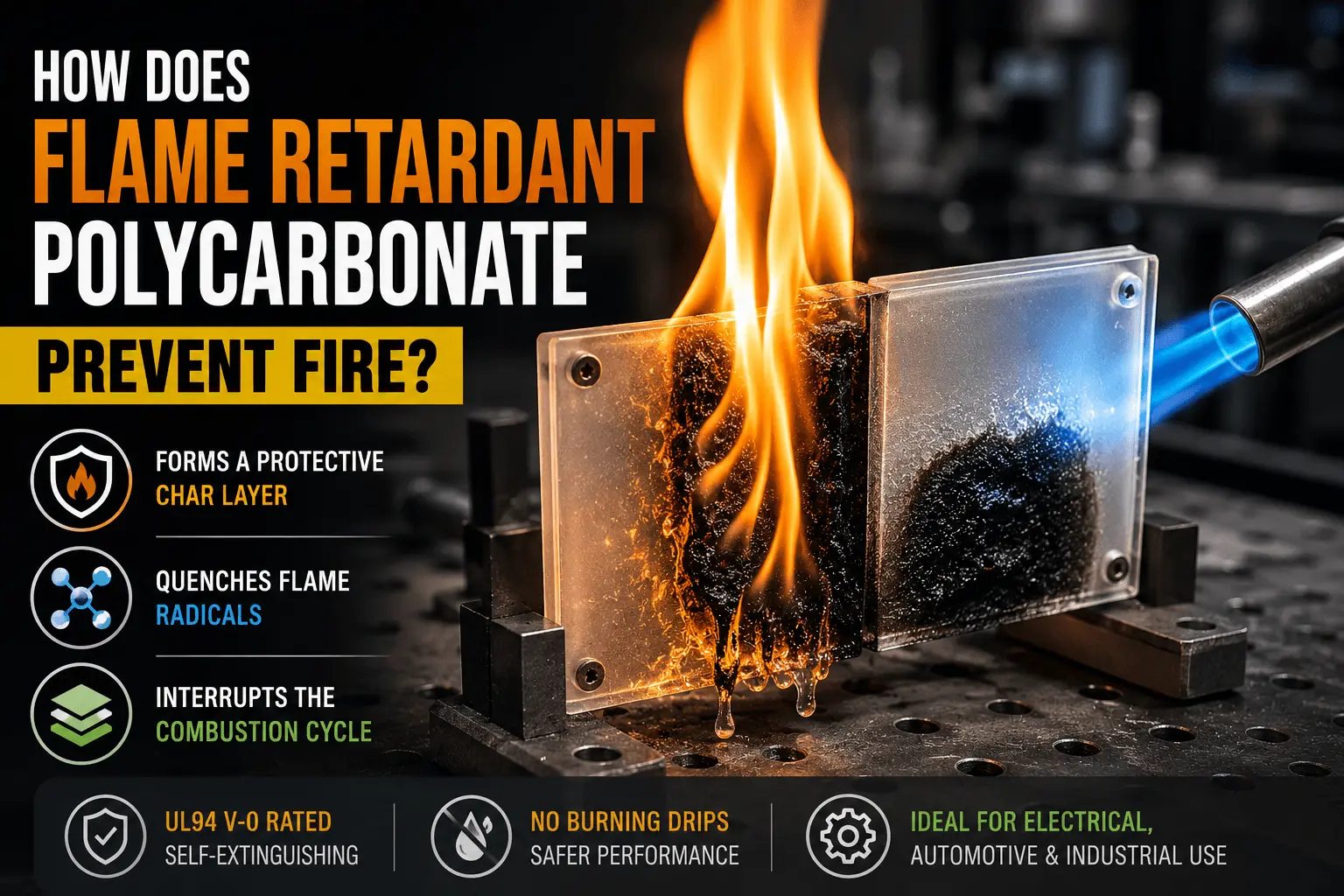
- A UL 94 rating is grade- and thickness-specific and describes standardized flammability behavior; it is not a thermal-runaway certification for a finished EV battery pack.
- Thickness cannot be selected from pack voltage alone. A 0.3, 0.5, 1.0, or 2.0 mm PC part may behave very differently depending on grade, shape, edge conditions, fastening, bending, and mechanical loads.
- For sourcing, the useful RFQ is a drawing-driven package: busbar geometry, voltage requirement, installation location, candidate material/grade, thickness, temperature, flammability requirement, adhesive needs, tolerance, validation plan, and annual volume.
Why Do EV Battery Busbars Need Insulation?
Busbars are deliberately conductive. Their job is to carry substantial current between cells, modules, contactors, fuses, junction units, or other high-voltage nodes with low electrical resistance. That same function creates an insulation challenge: the conductor may run close to grounded metal, another potential, a fastener, a sensing circuit, a module frame, or a pack cover. The insulation system must keep unintended conductive paths from developing during normal operation, assembly, vibration, contamination exposure, and service.
The engineering question is therefore not simply whether a sheet material has a high dielectric-strength value on its data sheet. IEC 60664-1 treats clearance, creepage distance, and solid insulation as related elements of insulation coordination. In a battery assembly, the applicable product and automotive requirements may differ, but the design principle remains useful: electrical separation is created by the complete geometry and environment, not by one material property in isolation.
Electrical separation around exposed conductors
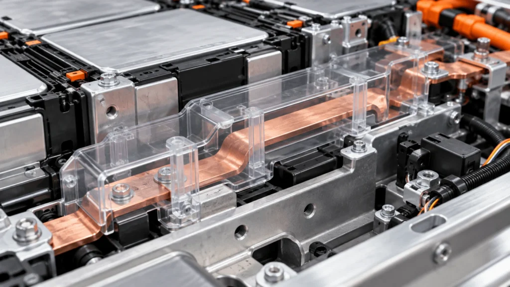
A busbar may need a cover over a broad flat section, a shield between the conductor and a metal enclosure, a formed piece around a bend, or a local insulator near a terminal or fastener. PC can be useful in these positions because it can act as solid insulation while also remaining physically present as a defined component. The design still has to preserve the required air gaps and surface paths where those paths form part of the insulation concept.
Assembly protection matters too
Many insulation problems are created before the vehicle ever operates. A cover can be displaced, a film can fold, a sharp edge can damage a thin layer, or a fastener can reduce the intended distance to a conductor. A rigid or semi-rigid PC component can make the insulation architecture easier to see, locate, fixture, and inspect during assembly. This does not eliminate assembly controls; it can make those controls more repeatable.
What Makes PC Suitable for Busbar Insulation?
Polycarbonate occupies a useful middle ground between very thin flexible films and much more rigid laminate boards. Commercial PC films and sheets are available in electrical and flame-retardant grades, and established material suppliers describe PC film as combining stiffness, toughness, heat resistance, and electrical insulation. Those characteristics explain why PC is frequently considered for protective electrical components, but the exact performance is grade-specific.
Electrical insulation
PC is an insulating polymer, so an appropriate grade can form a solid dielectric barrier between a busbar and adjacent conductive structure. For engineering selection, however, the team should review the actual grade data, thickness, environmental conditioning, required withstand tests, and the finished geometry. Dielectric strength is useful material information, but it should not be converted into a guaranteed component withstand voltage by multiplying a kV/mm value by nominal thickness.
Mechanical protection
Busbar insulation can be exposed to handling, fixture contact, fastener installation, vibration, and localized rubbing. PC’s toughness and shape retention can make it useful where a thin unsupported film would be difficult to keep flat or could be vulnerable to folding and handling damage. This is particularly relevant for covers and shields that must protect a conductor while also surviving production handling.
Dimensional stability
A die-cut or CNC-cut PC part can be designed with defined edges, holes, slots, tabs, and locating features. That can help a busbar cover remain aligned to the intended conductor and maintain a predictable relationship to nearby components. Large parts still require attention to flatness, thermal expansion, forming stresses, fastening, and tolerance stack-up.
Flame-retardant grades
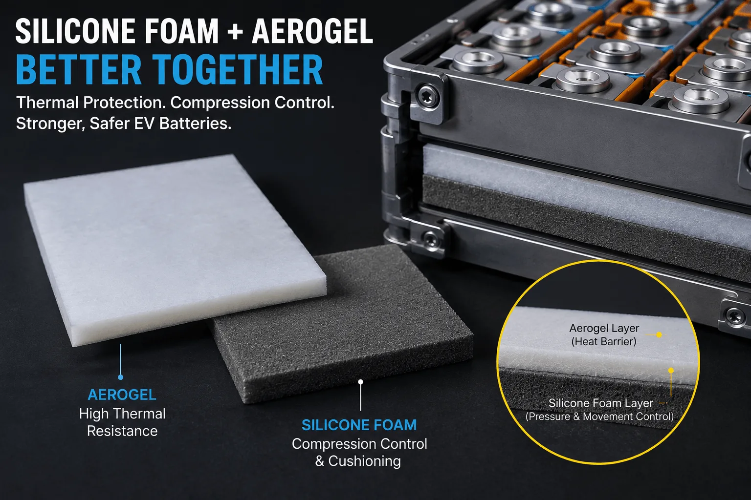
Flame-retardant PC grades are available, including grades carrying UL 94 classifications at specified thicknesses. The qualification belongs to the tested material and thickness, not to all PC. UL 94 is a small-scale flammability test under controlled conditions; it should not be presented as proof that a PC busbar cover will withstand a battery thermal-runaway event. If severe flame, hot gas, or particle exposure is a design case, the system may require mica, ceramic, aerogel, metal shielding, or another dedicated barrier in addition to or instead of PC.
How Does PC Protect EV Busbars From Accidental Contact?
A bare copper or aluminum busbar may be electrically safe on the CAD screen because its nominal distance to surrounding structures is sufficient. Real assemblies add tolerances, fasteners, harnesses, covers, tool access, deformation, and service operations. A shaped PC barrier can create a physical boundary that discourages unintended contact and helps keep neighboring parts away from the conductor.
This is especially useful where the insulator also acts as a cover. A PC cover can span a busbar, expose only the required terminal or bolted joint, and incorporate cutouts for sensing or fastening. It can also protect the busbar surface during module handling. The part must be designed so its own openings do not create a new weak point: a mounting hole placed too close to the conductor, for example, can shorten a surface path or expose an edge.
Why Choose PC Instead of Flexible Insulation Films?
Flexible PET and PI films can be excellent electrical insulation materials when the design needs a very thin, conformable dielectric layer. PC becomes more attractive when the part must also behave like a cover, shield, spacer, or self-supporting insulator. The choice is therefore functional rather than hierarchical.
| Design Need | PC Film/Sheet | PET or PI Film |
| Self-supporting cover or shield | Often well suited because stiffness can help retain shape | Usually needs support, lamination, forming, or attachment |
| Very thin conformal insulation | Possible in thin grades, but not always the most space-efficient choice | Often well suited |
| Complex folding around tight features | Depends on thickness, grade, and forming method | Generally more flexible |
| Handling protection | Toughness and stiffness can be advantageous | Performance depends strongly on film thickness and support |
| High-temperature severe-event barrier | Not the primary role of ordinary PC | Ordinary PET/PI selection also requires application-specific thermal assessment |
A common system-level solution is not to choose only one material. A rigid PC cover can provide geometry and handling protection while a thin film, adhesive layer, or high-temperature barrier addresses another requirement. The stack should be evaluated as an assembly because interfaces, adhesive edges, and fasteners can alter the electrical and mechanical behavior.
PC vs FR4 vs Mica for Busbar Insulation
PC, FR4, and mica can all appear in high-voltage battery insulation, but they solve different dominant problems. Treating them as interchangeable because all are electrically insulating obscures the design trade-offs.
| Material | Main Function | Typical Advantage | Design Consideration |
| PC | Rigid/semi-rigid polymer electrical cover or barrier | Tough, lightweight, dimensionally stable, readily converted into custom shapes | Grade, thickness, temperature, flammability, forming, and mechanical exposure must be verified |
| FR4 | Rigid glass-reinforced electrical laminate | High stiffness and mechanical support; machinable for structural insulation | Heavier/stiffer construction and machining may be unnecessary where structural support is not required |
| Mica | High-temperature dielectric and fire-facing barrier | Maintains useful insulation/barrier function at temperatures beyond ordinary thermoplastics | More brittle/less polymer-like in handling; reinforcement and edge design can matter |
For a busbar that mainly needs a shaped protective cover under normal battery operating conditions, PC may be a practical candidate. If the insulator must carry structural load, FR4 may deserve evaluation. If the critical case is direct high-temperature exposure, flame, hot gas, or molten particles, mica may address a requirement that ordinary PC does not. Hybrid constructions are also possible.
What Design Factors Affect PC Busbar Insulation?
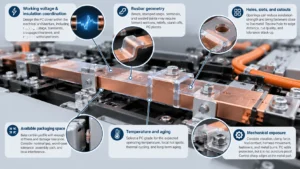
Working voltage and insulation coordination
Start with the electrical architecture: working voltage, voltage between the busbar and neighboring conductors or grounded structures, expected transients, required withstand tests, and the insulation class used by the system design. Then determine how solid insulation, creepage, and clearance are allocated. A PC cover should be designed within that architecture rather than used to compensate informally for an unresolved spacing problem.
Busbar geometry
Flat busbars are relatively simple to cover. Bends, stamped steps, terminal transitions, welded joints, and raised sensing features create local geometry that can concentrate mechanical contact or reduce separation. The PC part may need reliefs, formed sections, stand-offs, or multiple pieces. Internal corners should not be made arbitrarily sharp simply to match CAD geometry; manufacturability and stress during forming or installation must be considered.
Holes, slots, and cutouts
Every opening changes the component. Mounting holes can introduce fasteners close to live metal. Slots can reduce the width of the remaining insulation web. Large windows may expose a busbar edge. Cut quality and edge position therefore matter alongside nominal sheet properties. Hole-to-edge distance, hole-to-conductor distance, local stress, and tolerance accumulation should be reviewed on the finished drawing.
Available packaging space
Battery packs reward thin components, but thinner is not automatically better. The part needs enough stiffness and damage tolerance for its function while still fitting the available envelope. Designers should evaluate nominal gap, worst-case tolerance, assembly path, local interference, and any required movement during service.
Temperature and aging
PC grade selection should consider normal operating temperature, local hot spots, thermal cycling, and long-term aging. A busbar near a fuse, contactor, terminal joint, or power connection may see a different thermal environment from a general module cover. The relevant grade’s long-term property data and the finished assembly’s validation plan should drive the decision.
Mechanical exposure
Vibration, clamp force, tool contact, harness movement, fastener heads, metal burrs, and assembly fixtures can all change the mechanical demand on an insulation part. PC can add useful protection, but it is not puncture-proof. Sharp edges should be controlled at the metal part, not treated as something the polymer must indefinitely absorb.
How Thick Should PC Busbar Insulation Be?
There is no universal PC thickness for an EV busbar and no defensible rule such as “400 V equals 0.5 mm” or “800 V equals 1.0 mm.” Pack voltage is only one input. Thickness selection should combine electrical requirements with the actual PC grade, component geometry, mechanical protection, stiffness, forming needs, available space, manufacturing tolerance, and validation.
| Example Nominal Thickness | What It May Change | Questions to Ask |
| 0.3 mm | Low profile and easier flexing; less inherent stiffness | Will it stay located? Is handling damage controlled? Is the grade qualified at this thickness? |
| 0.5 mm | More shape retention while remaining relatively thin | Does it meet the mechanical and electrical test plan in the finished geometry? |
| 1.0 mm | Higher stiffness and stronger cover-like behavior | Does added thickness reduce clearance elsewhere or complicate forming/assembly? |
| 2.0 mm | Substantially more rigid structural behavior | Is this stiffness actually required, and can holes, bends, and tolerances be manufactured efficiently? |
These values are engineering examples, not recommendations. A thin grade with the right geometry may outperform a thicker poorly supported part for one function, while another application may require greater thickness for rigidity or damage tolerance. Flammability classifications must also be checked at the actual material thickness because UL 94 results are thickness-dependent.
Why Does PC Part Design Matter More Than Sheet Thickness?
A raw sheet is tested as material; a busbar insulator is installed as a component. The component has cut edges, holes, slots, corners, formed sections, adhesive zones, fasteners, and neighboring metal. Those features create the real electrical and mechanical boundary conditions.
- Holes can bring conductive fasteners closer to live busbars.
- Slots and windows can shorten local surface paths or leave narrow webs vulnerable to deformation.
- Sharp internal corners can increase forming or assembly stress.
- Poor cut edges can create dimensional inconsistency or handling damage.
- Bending can change local thickness, residual stress, and fit depending on the PC grade and process.
- Adhesive can improve retention but can also change thickness stack-up, edge geometry, reworkability, and contamination behavior.
- A cover that is electrically adequate but difficult to locate consistently can still be a weak production design.
For this reason, drawing review should happen before the material specification is frozen. The supplier needs to understand which dimensions are electrically critical, which features are only for assembly, and where tolerance can be relaxed to improve manufacturability.
How Does Die Cutting Improve PC Busbar Insulation Parts?
Die cutting is valuable when the busbar insulator is fundamentally a two-dimensional or lightly formed component produced at repeatable volume. It can create the perimeter, holes, slots, access windows, locating tabs, and adhesive-backed regions in one controlled converting workflow. CNC cutting can complement die cutting during prototypes, low-volume builds, thicker constructions, or geometries that are not yet stable enough to justify production tooling.
For PC busbar covers, DFM should review minimum web widths, hole size, internal radii, edge-to-hole distance, nesting, protective film, adhesive lamination, release liner design, and how the part will be picked and positioned on the line. The goal is not merely a clean shape; it is a component that can be produced, handled, installed, and inspected without undermining the electrical design.
Common Mistakes When Designing PC Busbar Insulation
- Choosing thickness from voltage alone. Voltage matters, but geometry, insulation coordination, material grade, mechanical function, and validation also control the design.
- Ignoring the metal edge condition. A sharp burr or unfinished busbar edge should be corrected rather than relying on PC to tolerate indefinite point loading.
- Treating every mounting hole as mechanically neutral. Holes change local stress, remaining web width, and the relationship between live metal and fasteners.
- Using raw-material dielectric data as finished-part performance. A data sheet does not include your cutouts, bending, adhesive, contamination, assembly tolerance, or aging.
- Assuming a V-0 grade is a thermal-runaway barrier. UL 94 describes standardized flammability behavior, not full-pack fire or propagation performance.
- Ignoring assembly tolerance. A cover that fits nominal CAD but interferes at worst-case stack-up can deform, lift, or shift.
- Selecting PC before defining the dominant function. If the requirement is extreme-temperature survival, structural load carrying, or ultra-thin conformal insulation, another material or multilayer construction may be more appropriate.
Industry Insights for High-Voltage Busbar Insulation
1. Higher voltage increases insulation demands, not a simple thickness number
As battery architectures move to higher voltage, designers must review the complete insulation system. Increasing PC thickness without checking creepage, clearance, transient conditions, pollution, interfaces, and the applicable validation tests can create false confidence.
2. Rigid insulation can make assembly more repeatable
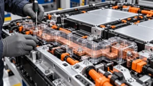
Where a thin film would need precise wrapping or could move during handling, a shaped PC cover can provide a visible, self-supporting component. That can simplify poka-yoke features, inspection, and automated placement, provided the part is designed for the actual assembly process.
3. Busbar geometry often drives the hardest insulation problem
The broad center of a flat conductor is rarely the only concern. Bends, terminal studs, welded joints, fasteners, sensor takeoffs, and transitions near grounded structure frequently determine the local insulation challenge. Material selection should follow a geometry review.
4. Compact packs increase the value of custom converting
As packaging space becomes tighter, generic rectangular sheets are less useful. Custom cutouts, tabs, local reinforcement, adhesive zones, and multi-material laminates can place material only where it contributes a defined function. This can support both space efficiency and assembly repeatability.
5. Finished-part validation is becoming more important than datasheet comparison
Material data helps screen candidates. Final confidence comes from representative components tested in relevant electrical, thermal, mechanical, environmental, and assembly conditions. Procurement teams should therefore compare not only resin or film data but also converting capability, traceability, tolerance control, and prototype support.
Engineering Selection Checklist
- Define the busbar-to-ground and busbar-to-busbar voltage relationships.
- Identify required clearance, creepage, and solid-insulation functions under the applicable system requirements.
- Map terminals, bends, welds, fasteners, brackets, sensing features, and nearby grounded metal.
- Define normal and abnormal temperature conditions for the installation location.
- State the required flammability classification and verify it for the exact PC grade and relevant thickness.
- Define whether the part must be flexible, semi-rigid, or self-supporting.
- Review burrs, sharp edges, point loads, vibration, and service access.
- Set critical tolerances separately from noncritical dimensions.
- Decide whether adhesive, liner, protective film, printing, or identification is required.
- Validate representative finished parts rather than relying on raw sheet data alone.
RFQ Checklist for Custom PC Busbar Insulation
- 2D drawing and, where useful, 3D CAD of the busbar and insulation part.
- Busbar material, geometry, and installation location.
- Working voltage and relevant insulation/test requirements.
- Preferred PC grade or required properties if the grade is not yet fixed.
- Nominal thickness and acceptable thickness range.
- Operating and peak temperature conditions.
- Required flame classification at the intended thickness.
- Critical holes, slots, edge distances, bends, and fastening features.
- Adhesive type, adhesive-free zones, liner, or protective-film requirements.
- Prototype quantity, annual volume, packaging method, and inspection requirements.
- Any component-level or assembly-level electrical, mechanical, or environmental validation requirements.
How Boost Insulation Supports Custom PC Busbar Insulation Parts
Boost Insulation’s public product information describes flame-retardant PC converting, DFM review, die cutting, CNC processing, multilayer lamination, and prototype-to-production support for EV battery insulation components. For a busbar project, the useful starting point is the drawing rather than a generic request for “PC insulation”. The engineering review can focus on material grade, thickness, critical geometry, hole and slot design, adhesive integration, tolerance, and the most appropriate converting route.
This approach is especially relevant when the busbar cover has to combine electrical isolation with repeatable assembly. A prototype can be used to confirm fit, access to terminals, interference at fasteners, handling stiffness, and whether the proposed cut geometry is production-friendly before tooling and volume production are finalized.
Frequently Asked Questions
Why is PC used for EV battery busbar insulation?
PC is used when a busbar needs an electrically insulating component that also benefits from toughness, stiffness, dimensional stability, and custom geometry. It can be converted into covers, shields, spacers, and barriers around high-voltage conductors. Suitability still depends on the exact PC grade, thickness, temperature, electrical architecture, mechanical exposure, and validation requirements.
Is PC better than PET for busbar insulation?
Not universally. PET is often attractive for thin, flexible film insulation, while PC can be more suitable when the part must retain shape or provide a self-supporting protective cover. The better choice depends on geometry, available space, mechanical exposure, temperature, flammability requirements, assembly method, and the qualified grade.
How thick should PC busbar insulation be?
There is no universal thickness based on pack voltage. Engineers should select thickness from the required electrical insulation function, PC grade, mechanical protection, stiffness, geometry, available space, flammability classification, manufacturing tolerance, and finished-part test plan. Values such as 0.3, 0.5, 1.0, or 2.0 mm are only candidate design points.
Can PC protect battery busbars from mechanical damage?
A properly designed PC cover can reduce handling contact, rubbing, and accidental contact with neighboring components, and its toughness can provide useful mechanical protection. It should not be used to excuse uncontrolled burrs, sharp metal edges, excessive clamp loads, or other mechanical hazards that should be corrected at the source.
Is flame-retardant PC suitable for EV batteries?
Flame-retardant PC can be suitable for many EV battery electrical-insulation components when the specific grade, thickness, temperature capability, electrical properties, and flammability classification meet the application requirements. A UL 94 rating alone does not qualify the finished component for thermal-runaway exposure.
Can PC insulation parts be die cut?
Yes. PC film and sheet can be converted into custom two-dimensional parts by die cutting, with CNC cutting useful for prototypes, thicker constructions, or evolving designs. Manufacturability depends on thickness, grade, hole size, narrow webs, corner radii, forming requirements, adhesive layers, and tolerance.
What information should be provided for custom PC insulation?
Provide the part drawing or CAD, busbar layout, voltage and insulation requirements, proposed PC grade and thickness, temperature and flame requirements, critical dimensions, holes and slots, adhesive or liner needs, prototype quantity, annual volume, and the validation or inspection requirements that apply to the finished component.
Conclusion: Treat PC Busbar Insulation as a Component
PC insulation can be a strong choice around EV battery busbars when the design needs electrical isolation plus a defined physical barrier, mechanical protection, dimensional stability, and manufacturable geometry. Its value is greatest when engineers stop treating it as a generic sheet and design it as part of the high-voltage assembly.
If you are developing custom PC insulation parts for EV battery busbars, send your drawing, busbar structure, insulation requirements, thickness preference, temperature conditions, adhesive requirements, prototype quantity, and annual volume for an engineering and manufacturability review.
Related Posts:
How Does a Mica Insulation Sheet Protect Battery Pack Lids?
What Affects the Price of Flame Retardant Polycarbonate?
Are Flow Batteries a Better ESS Solution Than Lithium-Ion?
How Do You Design Die-Cut PC Battery Insulation?
How Does Flame Retardant Polycarbonate Prevent Fire?
How Does Silicone Foam Work With Aerogel Barriers?
 betty wong
