
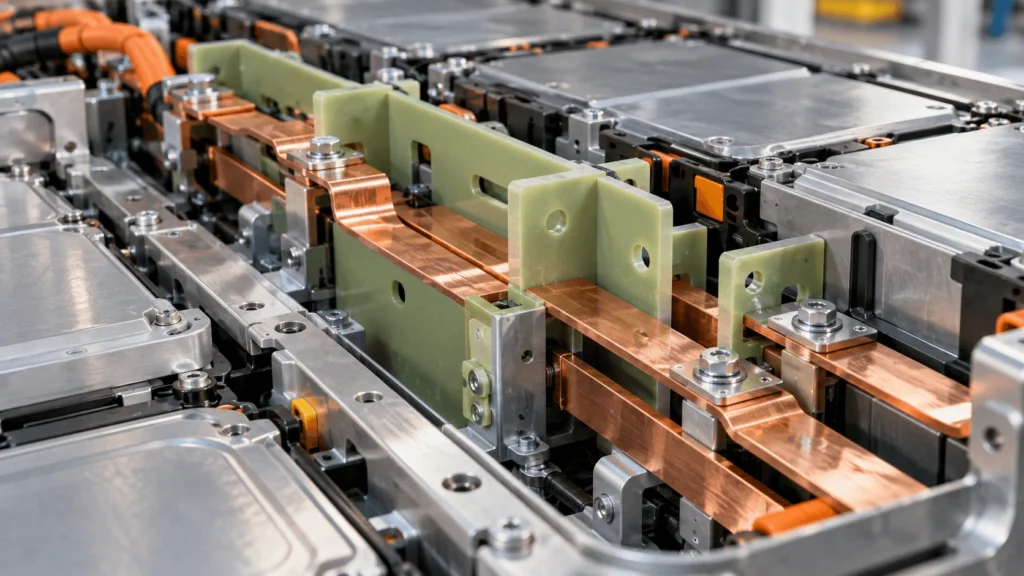
How Does FR4 Insulate EV Battery Busbars?
Table of Contents
An FR4 plate can sit between a high-voltage busbar and a metal battery structure, but simply placing an insulating sheet between two conductors does not guarantee electrical isolation. A possible discharge path may involve the laminate thickness, exposed surface, air gap, holes, fasteners, edges, or contamination around the component. Effective FR4 busbar insulation therefore depends on both material properties and geometry, with the finished part evaluated as part of the complete high-voltage assembly.
FR4 insulates EV battery busbars by acting as a solid dielectric barrier and by helping maintain controlled physical separation between energized busbars and nearby conductive structures. A properly designed FR4 component can interrupt a direct conductive path while its thickness, surface geometry, edges, holes, slots, and mounting features contribute to the overall insulation architecture. Effective busbar insulation must consider bulk dielectric performance together with creepage, clearance, contamination, humidity, fasteners, machining quality, and assembly tolerances. FR4 therefore functions as one engineered part of the high-voltage insulation system rather than as a standalone safety guarantee.
Key Takeaways
- FR4 busbar insulation works through a combination of solid dielectric separation, surface creepage geometry, air clearance, and stable mechanical positioning.
- Dielectric strength from a raw-laminate datasheet is not the same as the breakdown voltage or working-voltage capability of a finished machined part.
- Holes, slots, edges, bolts, washers, inserts, contamination, humidity, and tolerance stack-up can change the electrical geometry around a busbar.
- FR4 rigidity is valuable because it helps preserve electrical spacing and feature location; it does not eliminate creepage, clearance, or system validation requirements.
- For custom parts, electrical design and DFM should be reviewed together before the drawing is frozen.
What Electrical Problem Does FR4 Solve Around a Busbar?
Inside an EV battery pack, a busbar may run close to another busbar, a terminal, a module frame, a pack enclosure, a mounting bracket, or conductive hardware. The design problem is not simply to place a nonconductive material nearby. It is to prevent unintended contact and control all plausible electrical paths between energized and conductive structures while preserving those paths through manufacturing, assembly, vibration, and environmental exposure.
A custom FR4 component can serve as a barrier, divider, support board, mounting plate, insulating spacer, or terminal-separation panel. In these roles it can help prevent direct metal-to-metal contact, maintain defined geometry, and provide a solid dielectric layer. Its glass-reinforced construction also gives it board-like rigidity that can keep holes, edges, and mounting locations more stable than a thin flexible film in applications that require a rigid support geometry.
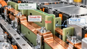
The Three Electrical Paths Around an FR4 Busbar Barrier
The most useful way to analyze FR4 busbar insulation is to separate the problem into three paths: through the solid laminate, along its surface, and through the surrounding air. Each path is controlled by different variables, and improving one path does not automatically correct a weakness in another.
| Path | Location | Main Design Control | Potential Failure Mode |
| Through FR4 | Through the solid laminate between conductive surfaces | FR4 grade, thickness, condition, defects, field geometry | Bulk dielectric breakdown |
| Along FR4 | Along an exposed insulating surface between conductive parts | Creepage geometry, material surface behavior, contamination, humidity | Leakage, tracking, surface discharge |
| Through air | Across the air gap between conductive parts | Clearance geometry, voltage stress, altitude/environment, transient conditions | Air breakdown or arcing |
1. Through-Material Path: How FR4 Provides Bulk Dielectric Isolation
FR4 is a glass-fiber-reinforced epoxy laminate used as an electrical insulating composite. When a properly specified FR4 barrier is placed between a busbar and a conductive structure, current cannot follow the direct metallic path that would exist if the two conductors touched. Instead, the electric field is applied across a solid dielectric whose performance depends on the actual laminate grade, thickness, material condition, test conditions, and finished geometry.
This is why a datasheet dielectric-strength value should not be multiplied by part thickness and treated as a guaranteed finished-part voltage rating. Datasheet tests use defined specimens and electrode arrangements. A real busbar component introduces edges, holes, fasteners, machining effects, temperature, humidity, local field concentration, mechanical stress, and assembly tolerances. Those conditions can make the finished insulation problem materially different from the raw-material test.
2. Surface Path: How FR4 Geometry Affects Creepage
Creepage is the shortest path along the surface of an insulating material between conductive parts. Around a busbar, that path may run from the copper or aluminum conductor across the FR4 surface toward a fastener, grounded frame, neighboring conductor, or terminal. Extending the insulating surface, repositioning conductive features, or using appropriate slots or geometric barriers can change the available surface path, but the effectiveness of those features depends on the complete insulation-coordination design.
Surface behavior is also environment-sensitive. Dust, process residue, metal particles, moisture, condensation, and other contamination can change leakage and tracking behavior. CTI and material-group concepts may be relevant under the applicable insulation-coordination framework, but CTI is not itself a creepage distance. Engineers should select creepage based on the applicable standard, working conditions, material data, and actual assembly rather than a generic number copied from another battery design.
3. Through-Air Path: Why FR4 Does Not Replace Clearance
Clearance is the shortest distance through air between conductive parts. An FR4 divider may help hold a busbar away from a metal enclosure or adjacent terminal, but the air path still exists around edges, openings, fasteners, and other exposed geometry. Clearance therefore remains a separate design requirement even when a solid FR4 barrier is present.
The current IEC 60664-1 framework addresses clearances, creepage distances, and criteria for solid insulation for equipment within its stated scope, including guidance related to altitude. Battery engineers must still determine which standards and vehicle-level requirements apply to their architecture. The key design point is that solid insulation, surface insulation, and air separation should be reviewed as distinct but interacting parts of the same system.
Creepage vs Clearance vs FR4 Thickness
| Parameter | Path | Controlled By | Why It Matters |
| FR4 thickness | Through solid laminate | Grade, thickness, laminate condition, field geometry | Influences the solid dielectric path and mechanical stiffness; it is not creepage or clearance. |
| Creepage | Along insulating surface | Surface geometry, material group/CTI where applicable, environment, contamination | Controls the available surface path between conductive parts. |
| Clearance | Through air | Air-gap geometry, voltage stress, altitude/environment, transients | Controls the shortest air path between conductive parts. |
How Can FR4 Help Reduce Busbar Short-Circuit Risk?
FR4 can help reduce the risk of unintended electrical contact by physically separating an energized busbar from nearby conductive structures. That function is useful where vibration, tolerance stack-up, busbar movement, assembly misalignment, loose hardware, or proximity to a metal frame could otherwise reduce separation. The barrier can also block a direct contact path for some foreign objects, depending on coverage and installation.
The wording matters: FR4 does not prevent every short circuit. Damage, incorrect assembly, conductive debris, insulation displacement, or an electrical path around the barrier can defeat the intended function. The design should therefore define what failure modes the FR4 part is meant to address and validate the finished assembly against those conditions.
Why Does FR4 Rigidity Matter Around Busbars?
For busbar insulation, rigidity is valuable because electrical geometry must remain stable. A thin film can provide excellent surface insulation when bonded or wrapped onto a conductor, but it may not hold a fixed gap across an unsupported region or maintain a precise hole pattern without another supporting structure. FR4 can combine electrical separation with board-like shape retention.
That rigidity can help maintain busbar-to-frame spacing, terminal position, divider geometry, fastener alignment, and barrier location. It should not be interpreted as automatic primary structural capability. Mechanical loads, unsupported span, vibration, fastener preload, and deflection still require application-specific validation.
How Does FR4 Thickness Affect Busbar Insulation?
Thickness affects both electrical and mechanical behavior. Electrically, it changes the solid dielectric path and may alter the location of conductive surfaces relative to edges and hardware. Mechanically, increasing thickness generally changes bending stiffness, deflection, hole stability, and behavior across unsupported spans. It also consumes packaging space, adds mass, changes fastener stack height, and may affect machining strategy.
Values such as 0.5, 0.8, 1.0, 1.5, 2.0, or 3.0 mm can be useful as example design gauges during packaging studies, but they are not universal recommendations. Availability and performance are grade-, supplier-, geometry-, and application-dependent. Thickness should be selected from the electrical requirement, mechanical support requirement, geometry, environment, and validation plan together.
Why Do FR4 Edges Matter Around High-Voltage Busbars?
A busbar edge, FR4 edge, and nearby conductive structure can form a locally demanding electric-field geometry. The FR4 edge may also mark the end of a surface creepage path and the beginning of an air-clearance path. As a result, barrier extension beyond the conductor, edge-to-conductor position, nearby grounded metal, and sharp conductive features should be reviewed together.
Machined edge quality also matters mechanically and electrically. Chipping, exposed fibers, delamination, dimensional error, or contamination can affect fit and surface condition. There is no universal FR4 edge extension that works for every battery pack; the correct geometry follows the applicable insulation-coordination requirements and the actual conductor arrangement.
How Do Holes Affect FR4 Busbar Insulation?
A hole is not electrically neutral. Mounting holes, terminal openings, connector cutouts, locating holes, and busbar openings remove material and may bring conductive hardware closer to an energized feature. A hole can shorten a surface path, change local clearance, reduce remaining cross-section, and create a local mechanical stress concentration.
The drawing should therefore identify which holes are electrically critical. Hole position relative to the busbar and nearby metal can matter more than a general perimeter dimension. Engineers should avoid assigning a generic minimum hole diameter or edge distance without considering the laminate, machining process, mechanical load, electrical geometry, and assembly tolerance.
How Do Fasteners Affect FR4 Busbar Insulation?
A conductive bolt, washer, insert, or threaded feature can change the electrical geometry of an otherwise insulating FR4 barrier. The relevant path may run from the busbar to a bolt head, around a hole, along the FR4 surface, or through air to a washer or bracket. Fastener preload can also create local crushing or cracking if the laminate and joint are not designed for the clamp load.
Review the bolt and washer as conductive objects, not just mechanical hardware. Hole clearance, washer diameter, edge distance, insert location, clamp load, creepage around the opening, clearance to the busbar, and tolerance stack-up should all be included in the insulation review. Rigid insulation is not immune to local mechanical damage.
Can Slots Increase Creepage Distance?
Slots can sometimes alter or extend a surface path, but they should not be added as a rule-of-thumb creepage fix. Their effectiveness depends on slot geometry, conductor location, applicable insulation-coordination rules, contamination, machining quality, and the way the part is installed.
A slot also removes material. It can reduce local stiffness, create narrow bridges, complicate machining, or move an air path closer to a conductor. Slot width, length, position, edge quality, and structural effect should therefore be reviewed electrically and mechanically. No universal slot dimension should be assumed.
How Does Contamination Affect FR4 Surface Insulation?
A clean FR4 surface and a contaminated FR4 surface are not equivalent electrical interfaces. Dust, metal particles, coolant residue, process residue, ionic contamination, moisture, and condensation can alter leakage and tracking behavior. In a high-voltage battery assembly, cleanliness is therefore part of insulation engineering rather than only a cosmetic manufacturing requirement.
The manufacturing plan should consider material handling, machining dust extraction, part cleaning, packaging, and assembly environment. Particular attention is warranted when equipment processes both insulating laminates and conductive materials, because cross-contamination can create risks that are not represented by the raw FR4 datasheet.
How Do Humidity and Condensation Affect FR4 Busbar Insulation?
Humidity and condensation primarily matter because they can change surface conditions and interact with contamination. A sealed pack, vented enclosure, cooling system, and local thermal gradients can produce different exposure conditions. FR4 should not be described as completely unaffected by moisture without grade-specific evidence.
Engineers should define the environmental condition expected at the busbar location and validate the material and geometry accordingly. Temperature/humidity aging, condensation exposure, insulation resistance, withstand testing, and other methods may be relevant depending on the product requirements and applicable standards.
How Does Machining Affect FR4 Electrical Insulation?
Custom FR4 busbar parts may require CNC routing, drilling, slots, cutouts, and profile machining. Those operations create the finished geometry that determines hole location, edge position, barrier extension, and fit. They can also create fiber exposure, edge chipping, delamination, dust, or dimensional variation if the process is not matched to the laminate and feature geometry.
This is another reason raw-laminate data cannot stand in for finished-component validation. A DFM review should identify electrically critical edges and openings, define appropriate inspection points, and ensure the cleaning process is compatible with the required surface condition.
Why Does FR4 Machining Dust Matter Around Busbars?
FR4 contains glass reinforcement and a resin matrix, so machining produces particulate debris. The engineering concern in this article is manufacturing cleanliness: loose debris should not remain on the component or migrate into a contamination-sensitive high-voltage assembly. FR4 dust should not automatically be characterized as conductive; the broader issue is controlling unknown contamination and residues around HV interfaces.
Dust extraction, tool condition, machine cleanliness, part cleaning, packaging, and final inspection should be aligned with the customer’s assembly requirements. Where mixed-material machining occurs, the process should also consider the possibility of conductive contamination from other operations.
How Tight Should FR4 Busbar Insulation Tolerances Be?
Tolerance strategy should follow electrical function and assembly stack-up. Busbar-to-FR4 edge position, busbar-to-hole distance, busbar-to-fastener clearance, slot geometry, terminal openings, barrier extension, and locating features may be electrically critical. A nonfunctional outer perimeter may not need the same control.
Applying tight tolerances everywhere can increase CNC time, inspection burden, tool wear, scrap, and cost without improving insulation performance. Instead, the drawing should identify the dimensions that preserve creepage, clearance, alignment, and fit. The manufacturing supplier can then review whether the proposed process can hold those requirements consistently.
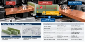
FR4 vs PC for EV Battery Busbar Insulation
FR4 and polycarbonate can both be used in electrical-insulation architectures, but they occupy different mechanical packaging roles. FR4 is especially relevant when the barrier also needs board-like rigidity and stable machined geometry. PC is often attractive for tough protective covers, thin shields, formed parts, and die-cut or thermoformed geometries. The correct choice depends on the grade, thickness, electrical design, mechanical function, fire requirement, manufacturing method, and installation.
| Design Requirement | FR4 | PC |
| Electrical insulation | Suitable with grade- and design-specific validation | Suitable with grade- and design-specific validation |
| Board-like rigidity | Strong use case | More flexible by comparison at similar packaging concepts |
| Tough protective cover | Application-dependent | Strong use case |
| CNC-machined support board | Strong use case | Possible depending on geometry and grade |
| Thin formed cover | Less typical | Strong use case |
| Hole / fastener stability | Strong use case; joint design still required | Geometry- and thickness-dependent |
| Severe heat / fire-facing barrier | Requires dedicated validation | Requires dedicated validation |
When Is Mica More Appropriate Around a Busbar?
If the dominant requirement is severe heat, flame, hot-gas exposure, or retention of dielectric function during a thermal event, engineers should evaluate mica or another dedicated high-temperature barrier rather than assuming FR4 is sufficient. A flame classification for a specific FR4 grade and thickness does not establish thermal-runaway barrier performance. The correct material depends on the required post-exposure function, heat flux, flame/particle exposure, mechanical geometry, and validation method.
What Controls Finished FR4 Busbar Insulation Performance?
| Design Factor | Electrical Impact | Mechanical / Manufacturing Impact | Validation Question |
| FR4 grade | Defines relevant dielectric/surface properties under specified tests | Affects machining and laminate behavior | Is the exact grade supported by supplier data for the intended conditions? |
| Thickness | Changes solid dielectric path and conductor geometry | Changes stiffness, stack height, machining | Does the selected gauge meet electrical and mechanical requirements? |
| Creepage | Controls surface path | Depends on finished edge/opening geometry | Is the minimum path preserved after tolerance stack-up? |
| Clearance | Controls air path | Depends on installed position and movement | Is the minimum air gap preserved in the assembled pack? |
| Busbar edge | Can concentrate field and terminate paths | Drives barrier extension and fit | Are sharp/high-field features accounted for? |
| Holes / slots | Can shorten paths or expose hardware | Remove section and add machining risk | Are electrically critical openings identified? |
| Fasteners | Can introduce conductive paths | Add preload and local stress | Are bolt, washer, insert and hole treated as one joint? |
| Surface condition | Affects leakage/tracking behavior | Depends on cleaning and handling | Is cleanliness controlled through shipment and assembly? |
| Humidity / temperature | Can change surface/material behavior | Affects aging and fit | Are environmental conditions represented in validation? |
| Tolerance / assembly | Can reduce creepage or clearance | Controls fit and repeatability | Does worst-case stack-up preserve the insulation geometry? |
FR4 Busbar Machining and DFM Checklist
| Feature | Electrical Risk | Manufacturing Risk | DFM Question |
| Hole | May reduce creepage/clearance or introduce hardware | Position error, chipping, delamination | Is this hole electrically critical and how is it inspected? |
| Slot | Changes surface and air paths | Narrow-tool access, edge quality, stiffness loss | Is the slot justified electrically and manufacturable mechanically? |
| Busbar opening | Can expose energized edges | Profile accuracy and edge finish | Does the opening preserve required barrier extension? |
| Fastener hole | Introduces conductive hardware near HV | Clamp damage and positional stack-up | Are bolt, washer and insert geometry included in the drawing review? |
| Narrow section | May reduce isolation coverage | Fragility and machining variation | Can the web retain mechanical integrity through assembly? |
| Internal corner | Can affect local geometry | Tool-radius limitations | Can the corner accept a realistic machined radius? |
| Large cutout | May shorten paths | Reduces stiffness | Is all removed material functionally necessary? |
| Critical tolerance | Can reduce designed electrical spacing | Raises CNC/inspection burden | Which dimensions truly control creepage, clearance or fit? |
Common FR4 Busbar Insulation Design Mistakes
- Selecting FR4 only from a dielectric-strength value.
- Multiplying datasheet kV/mm by thickness and treating the result as a guaranteed voltage rating.
- Ignoring creepage or treating it as the same thing as clearance.
- Ignoring the air path around an otherwise solid FR4 barrier.
- Ignoring busbar edge geometry and nearby grounded metal.
- Treating holes as electrically neutral features.
- Ignoring conductive bolts, washers, inserts, and threaded hardware.
- Adding slots without checking both insulation coordination and stiffness.
- Ignoring contamination, humidity, or condensation.
- Applying tight tolerances to every dimension instead of the electrically critical ones.
- Ignoring machined edge quality and post-machining cleaning.
- Using raw-sheet data as finished-component performance.
- Assuming a flame rating establishes thermal-runaway protection.
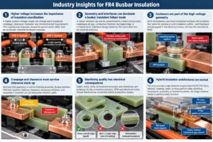
Industry Insights for FR4 Busbar Insulation
Higher voltage increases the importance of insulation coordination, not simply FR4 thickness. A higher system-voltage target can change solid-insulation, creepage, clearance, transient, and environmental requirements. The engineering response should be system-level rather than an automatic material-thickness increase.
Geometry and interfaces can dominate a busbar insulation failure mode. A robust laminate can still be undermined by a short surface path, inadequate air gap, conductive fastener, damaged edge, or contamination. Interface design deserves the same attention as material selection.
Fasteners are part of the high-voltage geometry. Bolts and washers can move conductive surfaces into locations that were not obvious in a 2D insulation outline. Joint hardware should appear in the electrical review, not only the mechanical BOM.
Creepage and clearance must survive tolerance stack-up. Nominal CAD geometry is not the finished assembly. Busbar position, FR4 hole location, fastener clearance, enclosure variation, and assembly movement can all reduce the minimum path.
Machining quality has electrical consequences. Edges, holes, slots, dimensional accuracy, and cleanliness are produced by the conversion process. DFM and electrical review should therefore be connected before production release.
Hybrid insulation architectures are normal. FR4 may provide a rigid dielectric board while PC/PET/PI films, sleeves, coatings, foam, or mica perform other electrical, mechanical, assembly, or thermal functions. No single material needs to perform every function.
Engineering Design Checklist for FR4 Busbar Insulation
- Working voltage and transient/overvoltage requirements
- Busbar polarity, material, dimensions, and edge geometry
- Adjacent conductors and grounded metal locations
- Required creepage and clearance under the applicable design framework
- FR4 grade, thickness, and supplier-supported material data
- CTI/material group where applicable
- Temperature, humidity, contamination, and condensation conditions
- FR4 edge extension and edge geometry
- Holes, slots, cutouts, fasteners, washers, and inserts
- Unsupported span, mechanical load, vibration, and fastener preload
- Critical electrical dimensions and mechanical tolerances
- Worst-case assembly stack-up and possible movement
- Machining method, edge requirements, cleaning, and inspection
- Finished-part and assembly validation requirements
RFQ Checklist for Custom FR4 Busbar Insulation
A useful RFQ gives the supplier enough information to review both electrical geometry and manufacturability. If the FR4 grade has not been selected, provide application conditions and required performance rather than simply requesting an unspecified ‘FR4 board.’
- 2D drawing (PDF / DXF / DWG where applicable) and 3D CAD if available
- Installation location and function of the FR4 part
- Busbar geometry and adjacent metal/conductor geometry
- Working voltage and relevant electrical-insulation requirements
- Creepage and clearance targets or governing design requirements
- FR4 grade if already specified; otherwise required performance conditions
- Thickness and overall dimensions
- Temperature, humidity, contamination, condensation, and flame requirements
- Hole, slot, cutout, terminal-opening, and locating-feature dimensions
- Fastener, washer, insert, and clamp details
- Critical electrical dimensions and critical mechanical tolerances
- Edge, surface, cleanliness, packaging, and inspection requirements
- Prototype quantity, annual volume, and validation requirements
How Boost Insulation Supports Custom FR4 Busbar Parts
Boost Insulation publicly lists FR4 and epoxy among the insulating materials it processes and describes in-house CNC capabilities, drawing review, material selection support, rapid prototyping, inspection, and precision converting. For a busbar project, those capabilities are most useful when the supplier receives the conductor geometry and electrically critical dimensions early enough to perform a manufacturability review before production release.
A practical project path is: Send Busbar Drawing → Electrical / DFM Review → Material and Geometry Review → Prototype → Validation → Production. The engineering review should identify critical holes, slots, edges, fastener interfaces, and cleanliness requirements without assuming a universal machining tolerance or electrical rating for every FR4 grade.
Frequently Asked Questions
How does FR4 insulate an EV battery busbar?
FR4 provides a solid dielectric barrier between an energized busbar and nearby conductive structures while its rigidity can help maintain the intended physical separation. Effective insulation also depends on creepage along the FR4 surface, clearance through air, edge geometry, holes, fasteners, contamination, environment, and assembly tolerance. The laminate is therefore one part of the complete insulation system.
Is FR4 suitable for high-voltage busbar insulation?
FR4 can be suitable for high-voltage busbar insulation when the exact laminate grade, thickness, geometry, environment, and validation requirements match the application. Suitability should not be inferred from the FR4 name alone. Engineers should review supplier data and the applicable insulation-coordination requirements, then validate the finished component and assembled electrical paths.
How thick should FR4 busbar insulation be?
There is no universal FR4 thickness for EV busbars. Thickness influences the solid dielectric path, stiffness, deflection, hole stability, packaging space, and fastener stack, but it is not a substitute for creepage or clearance. Select thickness from grade-specific material data, electrical requirements, mechanical geometry, environmental conditions, manufacturing constraints, and finished-part validation.
What is the difference between creepage and clearance around a busbar?
Creepage is the shortest path along an insulating surface between conductive parts. Clearance is the shortest path through air. FR4 thickness is a third, different path through the solid laminate. A busbar design can have adequate solid insulation but still have inadequate surface creepage or air clearance, so the three paths should be reviewed separately.
Can metal fasteners reduce FR4 insulation performance?
They can change the insulation geometry. A conductive bolt, washer, insert, or bracket may move metal closer to the busbar, shorten creepage or clearance, or introduce a new conductive path around a hole. Fastener preload can also create local laminate stress. The complete joint should be included in both electrical and mechanical validation.
Can slots increase creepage distance in FR4?
Slots can sometimes alter or extend a surface path, but their effectiveness depends on the applicable insulation-coordination rules, slot geometry, conductor position, contamination, and installation. A slot also removes material and can reduce stiffness or complicate machining. It should be added only after electrical and mechanical review, not as a generic creepage rule.
Is FR4 better than PC for EV battery busbar insulation?
Neither material is universally better. FR4 is particularly useful when the insulation needs board-like rigidity, mechanical support, and stable machined geometry. PC is often useful for tough protective covers, thin shields, and formed or die-cut components. Grade, thickness, electrical spacing, fire requirements, geometry, process, and assembly determine which construction fits the location.
Can FR4 protect busbars during battery thermal runaway?
FR4 should not automatically be treated as a thermal-runaway barrier because a grade is flame-retardant. If the busbar area may face severe flame, hot gas, particles, or high heat flux, engineers should evaluate the required post-exposure dielectric function and consider mica or other dedicated high-temperature barriers. The finished construction requires application-specific thermal and electrical validation.
Project CTA — Send Busbar Drawing → Electrical / DFM Review → Prototype
If you are developing a custom FR4 busbar insulation component, send your busbar and insulation drawings, working-voltage requirements, FR4 grade or material requirements, thickness, creepage and clearance targets, hole and slot geometry, fastener details, critical tolerances, prototype quantity, and annual volume for an engineering and manufacturability review.
Related Posts:
How Is Aerogel Used Between Prismatic EV Battery Cells?

How Thick Should PC Insulation Be in EV Batteries?
How Does FR Polycarbonate Compare to Flame Retardant PVC?
How Does Aerogel Slow Cell-to-Cell Heat Transfer in EVs?

Why Is Your ESS Storage Solution Losing Capacity Over Time?
Which Aerogel Grade Is Best for High-Voltage EV Cells?
 betty wong
