
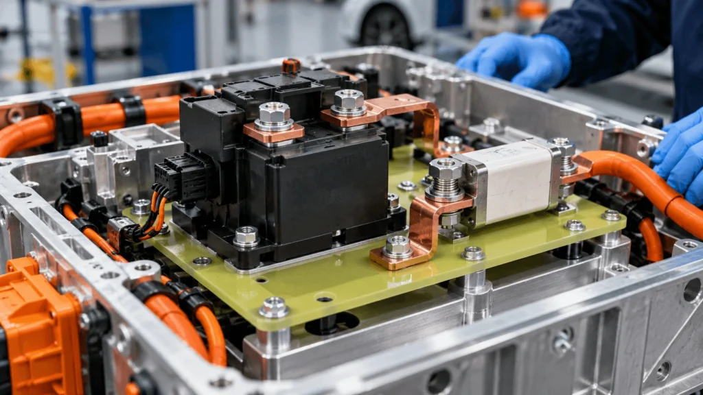
How Does FR4 Support EV Battery Contactors and Fuses?
A high-voltage contactor may arrive with an insulating housing, and a battery fuse may have its own mounting hardware. Yet installing either component inside a battery disconnect unit introduces new interfaces: bolted terminals, nearby busbars, grounded enclosure walls, clamp loads, vibration, and localized heat. A mounting plate that looks adequate on a CAD drawing may still distort, crack around a hole, or leave a conductive fastener too close to a live connection. How should FR4 be designed to support these components without compromising the high-voltage insulation system?
FR4 supports EV battery contactors and fuses by serving, where appropriate, as a rigid electrical-insulation mounting substrate. A custom glass-epoxy plate can locate component housings, provide support around mounting holes, and help preserve separation between high-voltage terminals, busbars, hardware, and surrounding metal. Its effectiveness depends on the selected laminate grade, component manufacturer’s mounting instructions, applied loads, fastener and washer design, creepage, clearance, local temperature, machining quality, and assembly tolerances. FR4 does not replace a contactor’s switching function, a fuse’s overcurrent protection, or the need to validate the complete high-voltage assembly.
What Problem Does an FR4 Mounting Component Solve?
A battery disconnect unit (BDU), high-voltage junction box (HVJB), or power distribution assembly has to locate electrical devices inside a compact enclosure. Contactors interrupt or connect the intended current path. Fuses protect against specified overcurrent or fault conditions. Neither function, by itself, dictates the correct material for the mounting base. Some devices are designed for direct chassis or panel mounting; others use dedicated holders or brackets. FR4 becomes useful when a separate rigid insulating panel is required by the electrical and mechanical architecture.
A well-specified plate can combine component location, controlled stand-off geometry, machinable mounting patterns, and a dielectric separation layer. This does not mean the plate should carry unrestricted busbar loads or substitute for a qualified structural frame. The critical question is whether the installed FR4 component maintains the manufacturer’s intended mounting conditions and the system’s insulation geometry after loading, aging, and assembly variation.
For broader context on material properties rather than specific hardware interfaces, see Boost’s FR4 rigid insulation for EV battery packs. This article instead focuses on the physical interfaces around contactors and fuses.
What Makes Contactor and Fuse Mounting Different?
A contactor is a switching device with a housing, actuator, coil or control connections, main power terminals, and defined attachment features. A fuse is an overcurrent protective device whose body, terminals, conductor attachments, and mounting arrangement vary with the product family. Example product information and mounting files are available from TE Connectivity. A fuse holder, a bolt-in fuse, and a pyrotechnically triggered disconnect should not be treated as interchangeable packages.
Table 1 — Contactor vs. Fuse Mounting Requirements
| Design factor | Contactor interface | Fuse interface | FR4 design implication |
| Primary function | Controlled HV switching | Specified overcurrent interruption | Plate performs neither electrical function |
| Mounting configuration | Housing flange, feet, or panel features, depending on model | Fuse body, bracket, holder, or terminal mounting | Use actual product drawing and installation method |
| Component loads | Mass, vibration, terminal forces, possible actuator reaction | Body support, terminal forces, conductor restraint | Establish distinct loads and support points |
| Electrical interfaces | Main terminals plus auxiliary/control connections | Fuse terminals and nearby busbars | Check all live metal and fastener positions |
| Thermal concern | Contact, coil and adjacent-system heating | Current-dependent fuse and connection heating | Review local temperature with the component supplier |
| Validation priority | Retention, terminal alignment, electrical spacing | Connection integrity, temperature and separation | Test assembled interface, not only a flat coupon |
How Does FR4 Provide Mechanical Support and Electrical Separation?
FR4 is a glass-fiber-reinforced epoxy laminate. In a suitable plate geometry it can provide board-like stiffness and a solid dielectric layer between a mounted device and another conductive structure. The laminated construction also makes it practical to machine component-specific outlines, openings, slots, and locating features. However, FR4 is a family of grades and constructions, not a universal performance specification; electrical and mechanical properties must be checked against an identified supplier’s data.
Mechanical and electrical suitability must be evaluated independently. A part may be rigid enough to hold a housing but expose a short air gap between a bolt head and live terminal. Conversely, an electrically acceptable barrier may deflect too far beneath component weight or preload. Its functional success is the combination of material, geometry, installation conditions, and validation—not a single datasheet property.
How Does FR4 Support a High-Voltage Contactor?
For an approved contactor configuration, an FR4 mounting plate can establish the relationship among housing mounting points, power-terminal locations, busbar entries, and the enclosure floor. Locating features may reduce assembly variability. Sufficient support under mounting feet can help keep the housing from tilting, while a controlled hole pattern avoids forcing attachment bolts into misalignment.
The load path is: contactor housing → prescribed attachment features → fasteners and bearing surfaces → FR4 plate → underlying supports. Every link matters. If the contactor manufacturer requires a particular mounting orientation, hardware arrangement, torque, or support surface, the FR4 design has to accommodate that instruction; it cannot simply replace a metal bracket because the laminate is insulating.
Does contactor operation load the mounting plate?
Potentially, but the answer is product-dependent. An electromechanical contactor contains moving mechanisms, and some switching operations may transmit reaction loads or vibration through its housing. The magnitude, direction, frequency, and relevance of those effects cannot be inferred from the word “contactor.” Review the manufacturer’s mounting requirements, expected operating duty, and dynamic qualification data. If a switching-related load is relevant, account for it in the assembled mounting system rather than assigning an invented force to FR4.
How Does FR4 Support a High-Voltage Fuse?
A fuse’s mounting interface depends on whether the selected product uses a dedicated holder, insulating body, bracket, or bolted terminals. FR4 can provide a support or separating panel where the fuse design and system architecture permit. It may help locate a holder, isolate a bracket from an enclosure, or maintain geometry around busbar connections. The plate must not impose undesirable stress on fuse terminals or change the intended current path.
Thermal design deserves particular attention. Current-related losses in the fuse and its connections can heat nearby hardware. Connection size, cooling, ambient conditions, and current cycling all influence fuse behavior. Mersen’s e-mobility overcurrent protection guide treats ambient temperature, airflow, and terminal connections as relevant to fuse selection. That does not establish a general permissible FR4 temperature beside any fuse. The laminate’s local thermal exposure requires separate, grade-specific review.
Normal-current thermal behavior and a fault-interruption event are distinct cases. A selected FR4 plate must not be presented as a fuse-arc containment component, an interruption enclosure, or a thermal-runaway barrier unless the actual assembly is specifically designed and validated for that duty.
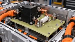
How Does FR4 Electrically Isolate These HV Components?
A solid laminate can interrupt direct conduction where it lies between a conductive part and the adjacent structure. But electrical insulation is not exclusively a through-sheet phenomenon. Terminal spacing, exposed surface paths, and air gaps can remain critical even when the substrate itself has good dielectric properties.
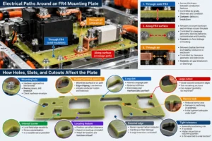
Table 2 — Electrical Paths Around an FR4 Mounting Plate
| Path | Where it occurs | Primary design controls | Possible concern |
| Through solid FR4 | Across thickness between opposing conductive features | Grade, thickness, condition, local damage, test method | Bulk dielectric breakdown |
| Along FR4 surface | Between exposed hardware and terminals across the plate | Creepage geometry, material tracking behavior, contamination, humidity | Surface leakage or tracking |
| Through air | Between busbar/terminal/bolt and nearby conductor or enclosure | Clearance geometry, voltage conditions, tolerances, environment | Air-gap breakdown or discharge |
Creepage is the shortest relevant distance along an insulating surface between conductive parts; clearance is the shortest distance through air. The applicability of distances and tests depends on the equipment and governing requirements. IEC 60664-1 provides a recognized insulation-coordination framework within its scope; it does not justify one generic distance for all automotive battery architectures.
Material dielectric strength measured on a test specimen is not the working-voltage rating of an assembled plate. Multiplying a datasheet kV/mm figure by the nominal thickness is not a finished-part breakdown guarantee. Edges, openings, mounting hardware, humidity, contamination, and geometric field concentration all affect practical behavior.
Why Do Terminal and Busbar Positions Matter?
The electrical geometry changes when the real contactor or fuse is attached. A washer may bring grounded or floating metal close to a high-voltage stud; a busbar bend may protrude beyond the nominal component outline; an adjacent fuse terminal may sit higher than the drawing’s base plane. Clearances must therefore be checked in an assembly model that includes fastener heads, washers, inserts, cable lugs, mating conductors, and allowable tolerances.
An FR4 opening may improve access but also expose a new edge or shorten a surface path. Likewise, adding a slot can alter creepage geometry, but its effectiveness depends on the governing measurement rules, slot dimensions, contamination conditions, and mechanical effects. A slot is not a substitute for electrical review. The mounting plate should be designed around a conductor-and-hardware envelope, not merely the device housing footprint.
How Do Busbar and Cable Forces Load FR4?
Busbars can transfer loads from imperfect alignment, thermal expansion, bolt tightening, and vibration into a component terminal or its mounting supports. Heavy cables may add weight and bending moments when unsupported. If those forces are allowed to pass into a relatively thin insulating plate, the plate can deflect even though its static strength appears acceptable.
The preferred design decision is often to manage conductor forces at the conductor or enclosure level—through alignment, independent supports, or suitable flexibility—rather than making the FR4 plate compensate for an unfavorable busbar route. Electrical connectors also need their manufacturer-specified loading and fastening practices respected. After assembly, check not only whether the plate survives but whether terminal alignment and conductor clearances remain within defined limits.
Table 3 — Mechanical Loads and Mounting Interfaces
| Load or interface | Potential effect | Design response | Validation question |
| Device mass and orientation | Plate sag or mounting tilt | Support positions, span, grade and thickness | Does the installed component retain alignment? |
| Busbar misalignment | Local bending into terminal or plate | Improve conductor routing and independent restraint | Are connection forces acceptably controlled? |
| Fastener preload | Local bearing stress or laminate damage | Hardware seating, washers, hole fit | Does clamp load remain within approved limits? |
| Vehicle vibration or shock | Movement, loosening, stress cycling | Retention design and assembly-level testing | Are clearances and mounting integrity retained? |
| Temperature change | Differential expansion and preload shift | Check interfaces and material/environment combination | Does geometry remain acceptable after cycling? |
| Switching reaction, if applicable | Repeated transient housing load | Use contactor-specific data | Is operational duty included in testing? |
How Do Vibration and Mechanical Shock Affect Reliability?
The mounting plate’s stiffness is not enough to establish vibration robustness. Dynamic loads act through the component’s mass distribution, mounting-point spacing, clamp load, and supporting frame. Repeated motion can also loosen connectors, wear a seating surface, or change the relative positions of a live terminal and nearby metal.
Evaluate the complete assembly: contactor or fuse, fasteners, FR4 substrate, enclosure support, attached busbar or cable, and nearby insulating features. Relevant verification may include retention, dimensional change, visual inspection, electrical spacing, and functional checks after a project-specific vibration or shock exposure. Avoid assigning a generic automotive vibration specification without confirming the actual system requirement.
Why Are Fuse Heat and Terminal Connections Special Risks?
A fuse can be correctly selected for electrical protection yet be installed in a thermal environment different from the manufacturer’s test setup. Ambient air, current profile, connection resistance, terminal mass, and cooling path influence local temperatures. A conductive bolt can transfer heat into adjacent hardware; a closely spaced mounting plate can experience localized exposure that is not represented by a general pack ambient temperature.
For the FR4 design, review normal operating and peak expected temperatures at the actual mounting surface, plus aging and thermal cycling. Separately determine whether fault-event exposure is part of the plate’s required duty. A laminate’s glass-transition data or flame classification is not a universal continuous-service rating, and UL 94 flame performance is not proof of battery thermal-runaway protection. If severe hot gas, flame, or post-event electrical isolation governs the requirement, evaluate a dedicated high-temperature solution; Boost’s mica-versus-FR4 comparison explains the different material roles.
How Do Fasteners, Washers, and Inserts Change the Design?
Fasteners are both mechanical and electrical interfaces. A metal bolt can bridge locations that are otherwise separated by FR4; a wide washer can extend toward a live busbar; an insert may add a conductive surface or change load distribution. An insulated plate does not automatically insulate the conductive hardware installed through it.
How Thick Should an FR4 Contactor or Fuse Mounting Plate Be?
No common plate thickness applies to all contactors or fuses. The minimum practical thickness is governed by the selected FR4 grade, support span, mounted mass, acceptable deflection, fastening conditions, electrical insulation requirement, packaging height, and machining feasibility. A thicker board can increase bending stiffness for a particular geometry, but cannot repair a deficient air clearance, overloaded connection, or inappropriate thermal environment.
Start with a candidate grade and thickness based on the actual load path and electrical requirements. Then model the machined geometry, mounting points, holes, and cutouts before prototyping. Compare the result with assembly deflection limits and electrical separation targets, then validate the complete part. Do not set a thickness solely from nominal battery voltage or a flat-sheet dielectric figure.
How Do Holes, Slots, and Cutouts Affect the Plate?
A solid rectangle and a routed mounting plate with large terminal windows do not behave the same. Openings remove material, alter local stiffness, move loads into narrow ligaments, and introduce edges close to conductors. Internal corners may concentrate mechanical stress; locating slots may improve assembly adjustability but increase positional variability if not controlled.
Table 4 — CNC/DFM Review for FR4 Mounting Plates
| Feature | Electrical risk | Mechanical/manufacturing risk | DFM question |
| Mounting hole | Hardware approaches live terminal | Bearing stress, drill breakout | Is hardware envelope shown in the drawing? |
| Busbar/terminal opening | Shortened surface or air path | Edge chipping, interference | Is conductor motion and tolerance included? |
| Long slot | Altered creepage path | Reduced stiffness, routing limits | Is the slot electrically and mechanically justified? |
| Large cutout | Closer exposed conductive edges | Thin remaining sections | Can support geometry be improved? |
| Internal corner | Local field/edge sensitivity | Stress concentration | Is a suitable radius possible? |
| Narrow web | Reduced barrier area | Damage in machining or assembly | Is the ligament adequate under load? |
| External edge | Barrier may end before conductor | Handling or fiber damage | Is edge extension controlled? |
| Locating feature | Position can affect clearance | Datum or stack-up mismatch | Which dimensions are function-critical? |
| Tight tolerance | Assembly positioning risk if too loose | Higher inspection or machining burden | Is the value tied to a real function? |
Machining quality matters because routed edges, drilled holes, and surfaces become part of the finished insulation system. Review fiber exposure, chipping, delamination, surface condition, flatness where necessary, and residual particles. FR4 machining dust is not inherently equivalent to conductive debris, but mixed-process metal particles, process residue, and retained contamination warrant control in an HV assembly.
Material thickness tolerance, hole-position tolerance, flatness, and profile tolerance are different requirements. Critical dimensions should be defined from electrical and mounting datums; cosmetic boundaries generally need not receive equally restrictive tolerances. This improves both manufacturability and inspection clarity.
What Else Controls Finished Mounting-Plate Performance?
Table 5 — Finished FR4 Contactor/Fuse Support Review
| Design factor | Mechanical impact | Electrical impact | Key validation question |
| Laminate grade | Grade-specific stiffness and aging | Grade-specific dielectric behavior | Is the exact approved grade documented? |
| Thickness and span | Deflection and support | Through-solid path, component spacing | Is installed geometry within limits? |
| Component mounting points | Load distribution | Hardware location | Are maker-specified attachments maintained? |
| Holes, slots, cutouts | Local stiffness and stress | Creepage, clearance, exposed edges | Does the machined part preserve design margins? |
| Fasteners and washers | Clamp load and retention | Possible conductive bypass | Has the full hardware stack been modeled? |
| Busbar/cable forces | Bending and terminal stress | Movement affects spacing | Are conductor loads controlled? |
| Fuse-side temperature | Expansion, aging | Grade-dependent insulation change | Is actual local exposure verified? |
| Vibration and shock | Relative movement or loosening | Clearance shift | Does assembled testing reflect service duty? |
| Machining and cleaning | Edge integrity and fit | Surface condition and debris | Are finished parts inspected clean? |
| Tolerances and assembly | Misalignment or interference | Minimum actual conductor separation | Is worst-case stack-up reviewed? |
FR4 vs. PC vs. Mica: When Is Each Appropriate?
FR4 can be attractive where a flat, rigid, machinable dielectric substrate is needed. A suitable PC grade may be preferable for a formed or impact-tolerant protective cover rather than a board-like mounting plate. Mica-based systems warrant consideration for severe heat or flame-facing dielectric barriers. These are functional distinctions, not blanket rankings, and hybrid designs may combine several layers.
Table 6 — Material Roles Near HV Components
| Design requirement | FR4 glass-epoxy | PC or other polymer | Mica/high-temperature barrier |
| Rigid machined mounting substrate | Strong candidate when grade and loads suit | Possible; mechanical design differs | Depends on construction; not assumed structural |
| Thin formed protective cover | Generally less natural | Often useful with suitable grade | Application dependent |
| Solid electrical barrier | Grade/geometry dependent | Grade/geometry dependent | Grade/construction dependent |
| Severe flame or hot-gas exposure | Requires dedicated assessment | Requires dedicated assessment | Often evaluated for this specific role |
| Fastener-supported interface | Validate local bearing and edges | Validate creep and mechanical behavior | Validate brittleness, hardware and mounting method |
Increasing FR4 thickness is not always preferable to changing support positions, conductor routing, or the material system. If another material better matches the required deformation, thermal exposure, or package shape, the design should be reconsidered before the FR4 gauge is increased.
When Should Engineers Avoid an FR4 Mounting Plate?
FR4 is not automatically appropriate where the device is already qualified for a different mounting scheme, where required mechanical loads are beyond the validated laminate-and-joint design, where temperature or fault exposure exceeds the grade’s demonstrated capability, or where electrical clearances cannot be achieved in the proposed shape.
Treat these as design gates, not statements that FR4 is unsuitable for all heavy or hot applications. Material selection follows the actual load case, operating conditions, component maker’s constraints, and validation plan.
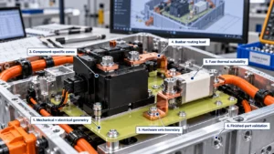
Six Engineering Insights for Contactor and Fuse Supports
Insight 1 — Co-design mechanical and electrical geometry. A thicker support can reduce deflection but leave a fastener dangerously close to a terminal. Review load paths and conductor paths in the same CAD assembly.
Insight 2 — Contactor and fuse interfaces are not interchangeable. The contactor may present switching-related or housing loads; the fuse requires close attention to terminal heating and connection configuration. A shared plate still needs component-specific zones.
Insight 3 — Hardware may set the insulation boundary. A bolt head, insert, or washer can be the nearest conductor rather than the device housing. Include real hardware envelopes early.
Insight 4 — Conductor routing can dominate plate loading. If a misaligned rigid busbar strains the terminal, increasing FR4 thickness may only move the failure into the component or joint. Control force where it originates.
Insight 5 — Fuse thermal suitability is a separate decision. Normal current heating, environmental aging, and fault-event exposure cannot be reduced to a generic flame classification. Specify the exact service scenario.
Insight 6 — Finish the design on a finished part. Machining, cleaning, mounting preload, tolerances, and vibration can change both mechanical position and electrical spacing after the material grade is chosen.
Common FR4 Contactor and Fuse Mounting Mistakes
A useful review catches more than material errors. Frequent mistakes include:
- selecting FR4 solely because it is rigid;
- ignoring the manufacturer’s mounting drawing;
- omitting component mass and orientation;
- ignoring shock or vibration;
- forcing a misaligned busbar into place;
- assuming FR4 insulates every metal fastener;
- neglecting creepage;
- neglecting clearance;
- omitting terminal/washer envelopes;
- ignoring bearing area and preload;
- treating fuse heating as negligible;
- ignoring weakened webs around openings;
- placing tight tolerances on nonfunctional edges while missing critical hole locations;
- assigning raw-sheet data to the finished part; and
- treating FR4 flame classification as evidence of thermal-runaway protection.
Engineering Design Checklist
Before freezing the plate design, confirm the following groups of inputs:
- Hardware and location: Contactor/fuse maker, part number, controlled drawing, installation instructions, BDU/HVJB location, mounting orientation, housing envelope, component mass.
- Electrical: Actual voltage across relevant insulation, transient conditions, creepage/clearance criteria, terminal and busbar positions, nearby metal, fastener conductivity, contamination environment.
- Mechanical: Support points, spans, mounting pattern, shock/vibration duty, allowable deflection, busbar/cable loads, component-specific switching reactions where documented, clamp-load and washer/insert design.
- Thermal and material: FR4 grade, selected thickness, operating and local hot-spot exposure, fuse normal-current thermal conditions, fault-event requirements if applicable, humidity and aging.
- Manufacturing and validation: Holes, slots, cutouts, edge requirements, datums, critical tolerances, flatness, CNC method, cleaning, inspection, assembled electrical/mechanical tests, change-control requirements.
RFQ Checklist for Custom FR4 Contactor and Fuse Supports
A technical RFQ should include the 2D drawing (PDF/DXF/DWG as applicable), 3D CAD if available, contactor and fuse part numbers with current datasheets, exact mounting layout, enclosure location, busbar and nearby-metal geometry, working/transient voltage conditions, creepage/clearance criteria, requested FR4 grade and thickness if known, and local thermal/environmental requirements.
Also provide component mass, expected loads and vibration duty, mounting orientation, support span, mounting-hole/slot/cutout dimensions, fastener/washer/insert data, assembly requirements, critical datums and tolerances, edge/cleanliness instructions, prototype quantity, expected annual volume, inspection criteria, and validation responsibilities. If material or thickness is undecided, provide application requirements rather than simply asking for “FR4 board for contactor“.
How Boost Insulation Can Support Custom FR4 Component Reviews
Boost Insulation describes battery-module material selection and DFM support, drawing-based review, custom processing, and CNC capability on its EV battery module insulation page. For a contactor or fuse mounting concept, those general capabilities can support a preliminary discussion about grade availability, part outline, machining feasibility, holes and slots, handling, and inspection needs. The site information should not be interpreted as an independently verified FR4-specific load qualification, an approved contactor design, or a guarantee of electrical safety.
A practical project path is: send component drawings → electrical/mechanical DFM review → material and geometry discussion → prototype → customer assembly validation → production review. Component manufacturers and the battery system design authority remain responsible for specifying and approving the relevant HV interface requirements.
Frequently Asked Questions
1. How does FR4 support EV battery contactors and fuses?
FR4 can provide a rigid insulating plate that positions selected contactors or fuses relative to busbars, fasteners, and surrounding metal. The plate may carry defined mounting loads and help maintain the intended electrical geometry. Its suitability depends on the component’s installation instructions, laminate grade, support span, temperature, fastening design, and finished-part testing. FR4 itself neither performs switching nor provides overcurrent interruption.
2. Can FR4 be used as a contactor mounting plate?
Yes, when the actual contactor manufacturer permits the mounting configuration and the plate has been engineered for the resulting loads and electrical spacing. The design should incorporate the approved hole pattern, housing support, washer and fastener geometry, busbar interfaces, and environmental duty. A contactor with an insulating housing does not automatically make its external mounting hardware electrically isolated.
3. Can FR4 support a high-voltage battery fuse?
It can be a candidate for a fuse holder support or insulating mounting panel, depending on how that specific fuse is designed to be installed. Engineers must consider terminal connections, conductor forces, clamp loads, and normal-current heat near the fuse. The manufacturer’s installation and thermal guidance is essential. A general FR4 flame rating is not evidence that the mounting plate can contain a fuse fault event.
4. Does an FR4 mounting plate electrically insulate metal fasteners?
Not automatically. A conductive bolt, washer, threaded insert, or spacer may create a conductive bypass or reduce clearance to a nearby energized terminal. The plate isolates only the paths its actual geometry and material interrupt. Model the complete metal hardware stack and check through-material insulation, creepage, and clearance under final assembly tolerances rather than assuming an insulating substrate makes all attached parts safe.
5. How do vibration and busbar forces affect FR4 mounting parts?
Vibration can alter component retention, connection loading, and relative conductor positions. Rigid busbars may also impose bending forces from thermal expansion or assembly misalignment, while unsupported cables add loads. These effects depend on the real system design. Where possible, manage conductor forces independently and test the assembled component, plate, fasteners, and supports rather than relying on raw-laminate stiffness alone.
6. How thick should FR4 be for contactor and fuse mounting?
There is no universal thickness for these applications. A candidate thickness must meet electrical insulation requirements, mechanical load and deflection limits, fastener bearing needs, available packaging space, and manufacturing constraints. The selected laminate grade and support span matter as much as nominal gauge. Higher battery voltage does not map directly to a fixed FR4 thickness; creepage, clearance, and completed assembly validation remain separate requirements.
7. Can fuse heat damage an FR4 mounting plate?
Potentially, if local operating or abnormal thermal exposure exceeds the selected laminate’s demonstrated capability. Temperature near a fuse is influenced by current, cooling, ambient conditions, and terminal connections. Assess the actual fuse manufacturer data and expected hot-spot conditions at the plate. Normal-current heating must be distinguished from fault interruption or battery thermal-runaway exposure, which may require a different protective material system.
8. What should engineers validate before using FR4 to mount HV components?
Validate the specific material grade, finished thickness and geometry, mounting-hole and washer interface, component alignment, electrical spacing, local temperature, and relevant vibration or shock exposure. Electrical withstand or insulation resistance tests may be appropriate under the system’s approved plan, alongside mechanical, thermal, dimensional, and post-test inspections. Qualification must be based on the installed component and the applicable project requirements, not a generic FR4 datasheet.
Conclusion: Review the Mounted Assembly, Not Just the Laminate
FR4 can be an effective rigid electrical substrate for selected EV battery contactor and fuse installations because it combines machinable mounting geometry with a solid dielectric separation function. The decisive factors, however, are the actual component interfaces: manufacturer mounting instructions, fastener paths, conductor loads, terminal spacing, vibration, and fuse-side thermal exposure. Material selection is only the beginning; the machined and assembled part must be evaluated against the battery system’s requirements.
Developing a custom FR4 contactor or fuse mounting part? Send your contactor/fuse drawings and part numbers, mounting layout, busbar geometry, voltage and insulation requirements, material/thickness preferences, fastener details, environmental conditions, critical tolerances, prototype quantity, and estimated annual volume for a material and DFM discussion. Contact Boost Insulation.
Related Posts:
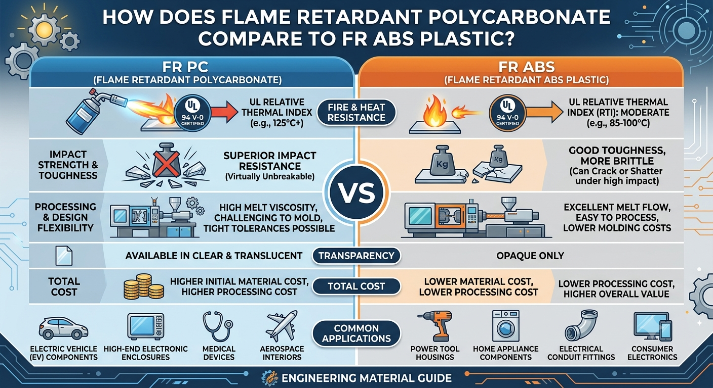
How Does Flame Retardant Polycarbonate Compare to FR ABS Plastic?

Why Is Your ESS Storage Solution Losing Capacity Over Time?
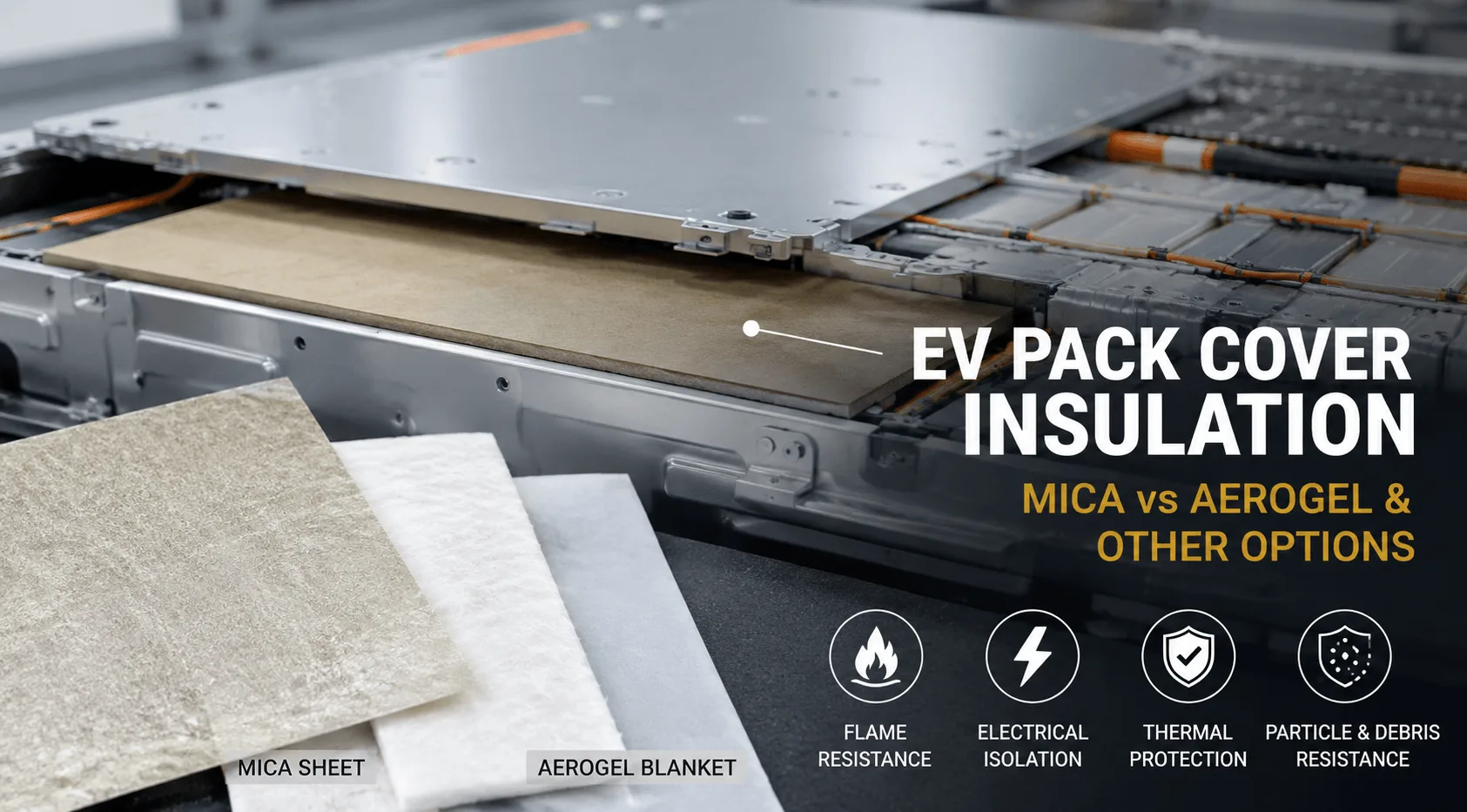
Which Insulation Material Is Best Under EV Pack Covers?
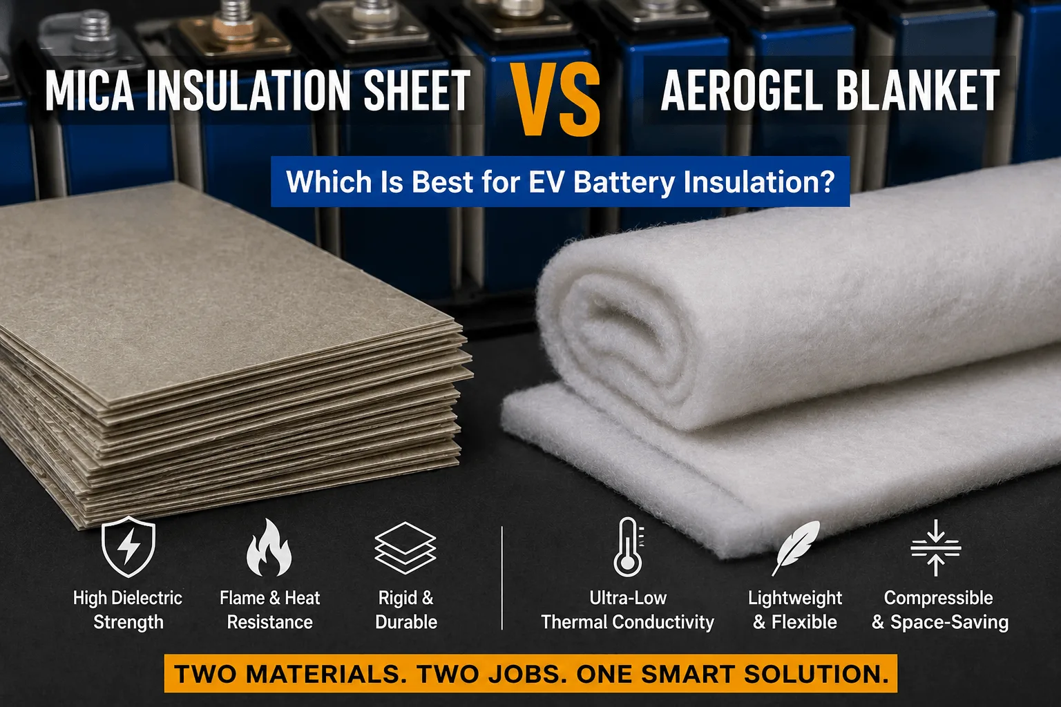
Is a Mica Insulation Sheet Better Than Aerogel for EVs?
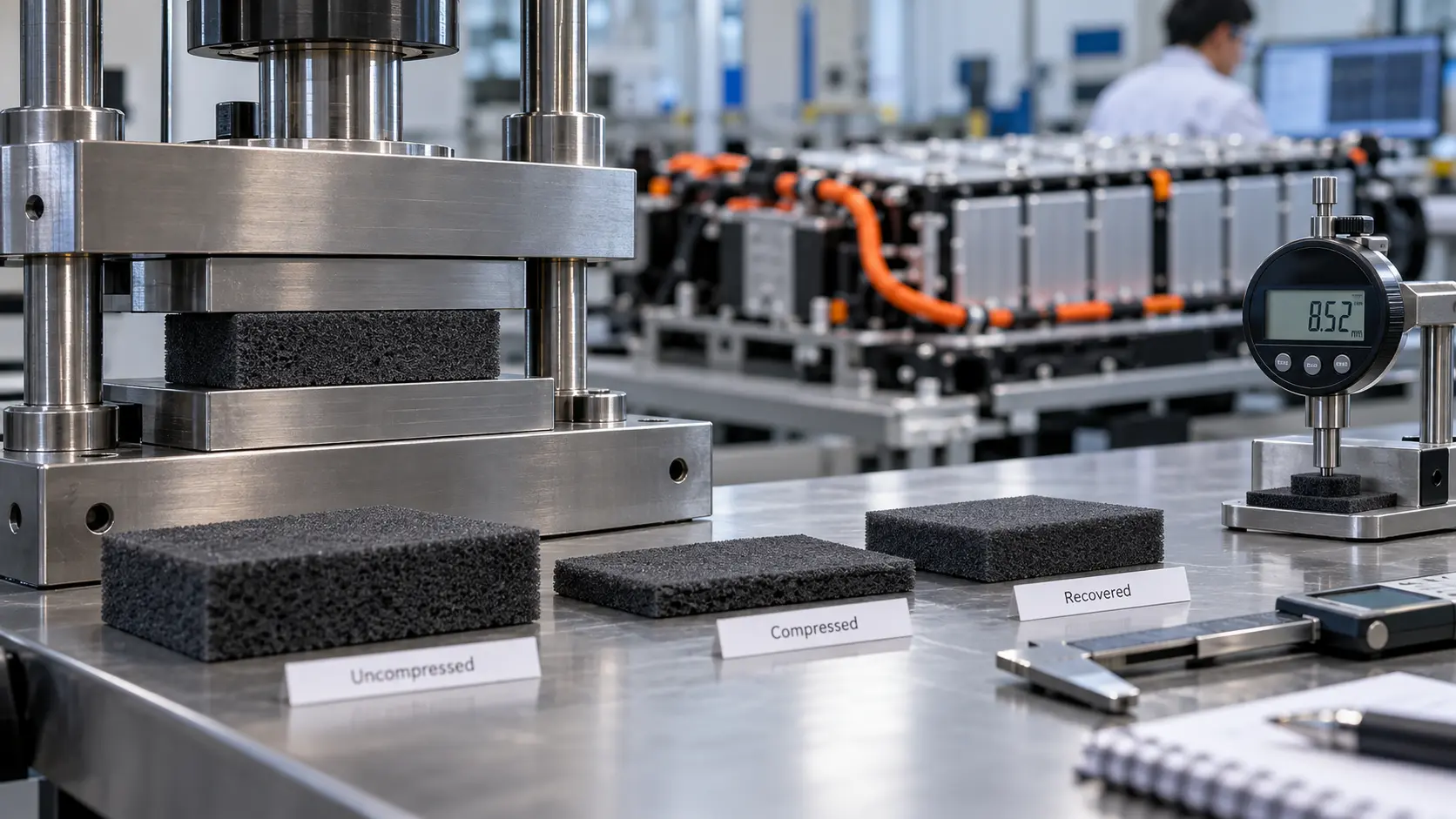
How Do You Test Silicone Foam Recovery in EV Battery Pads?
What Insulation Does an Energy Storage System Need?
 betty wong
