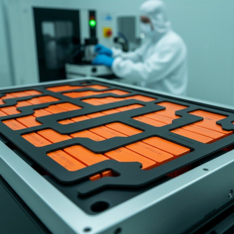
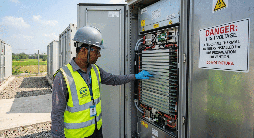
How Does Cell-to-Cell Thermal Barrier Improve ESS Safety?
Table of Contents
One overheating cell. That’s all it takes. In a battery system without proper thermal isolation, a single cell experiencing thermal runaway can cascade through an entire module — then a rack — then the whole container — in under three minutes. It has happened at utility-scale installations on three continents. The fires burned for days. The financial losses ran into tens of millions. And in every post-incident investigation, the same question emerged: why wasn’t thermal propagation physically blocked at the source?
Cell-to-cell thermal barriers are the engineering answer to that question. They are one of the most important — and most frequently under-specified — safety components in a modern ESS storage solution. If you’re evaluating an ESS for a commercial, industrial, or utility project, understanding exactly what thermal barriers do, how they work, and what the benchmarks are is not optional technical reading. It’s due diligence that could prevent a catastrophic loss.
This guide gives you that understanding — clearly, completely, and without the marketing language.
⚑ QUICK ANSWER
1. The Danger Without Thermal Barriers: Understanding Thermal Runaway
To understand what thermal barriers do, you first need to understand the threat they defend against: thermal runaway — the most dangerous failure mode of lithium-ion battery cells.
What Is Thermal Runaway?
Thermal runaway is a self-reinforcing exothermic reaction within a lithium cell. It occurs when cell temperature rises above a critical threshold — typically 80–120°C for LFP cells, lower for NMC — triggering a sequence of chemical decomposition reactions that generate more heat than the cell can dissipate. The reactions accelerate, temperature climbs further, and within seconds the cell enters an uncontrollable state, venting hot gases, electrolyte vapour, and — in severe cases — ejecting molten material or igniting.
The Propagation Problem
A single cell experiencing thermal runaway would be manageable in isolation. The catastrophic danger is propagation: the thermal energy released by one failing cell — which can reach 400–800°C at the cell surface — transfers to its neighbors through direct conduction, convective gas flow within the module, and radiant heat. Within 30–90 seconds of initial failure, adjacent cells reach their own runaway threshold. The cascade accelerates exponentially.
⚠️ Critical Insight
Laboratory testing has demonstrated that in battery modules without thermal barriers, a single initiating cell thermal runaway event can propagate through an entire 16-cell module in under 90 seconds.
With well-designed cell-to-cell thermal barriers using phase-change materials, the same test shows zero propagation to adjacent cells after 10 minutes — the full UL 9540A test duration.
Why BMS Alone Is Not Enough
A common misconception among ESS buyers is that a good BMS provides sufficient protection against thermal runaway. It does not. The BMS detects the conditions that precede thermal runaway — rising cell temperature, voltage deviation, gas sensor triggers — but once a cell enters thermal runaway, the BMS cannot stop the electrochemical reaction. The BMS can only respond: isolate the string, alert the EMS, trigger fire suppression. These responses take time. Without a physical thermal barrier slowing propagation, that time doesn’t exist.
Cell-to-cell thermal barriers buy that time. They are the passive, materials-science solution that works instantly, without software, without power, and without any signal latency. That is why they are a structural requirement in every professionally engineered ESS module — not an optional add-on.
2. What Is a Cell-to-Cell Thermal Barrier?
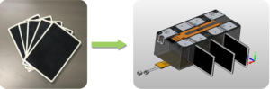
A cell-to-cell thermal barrier is a precisely engineered material insert — typically a pad, sheet, or form-in-place compound — positioned between individual battery cells or between cell groups within a battery module. Its sole purpose is to interrupt, slow, or absorb heat transfer between adjacent cells during an abnormal thermal event.
Thermal barriers are distinct from the general thermal interface materials (TIMs) used between cells and cooling systems. TIMs are designed to conduct heat efficiently toward the cooling circuit during normal operation — they facilitate heat removal. Thermal barriers, by contrast, are designed to resist heat transfer during fault conditions — they block propagation. The two functions are sometimes combined in advanced material formulations, but the distinction in design intent is important.
Where Thermal Barriers Are Installed
In a prismatic LFP module (the most common architecture in commercial ESS), thermal barriers are installed:
- Between individual prismatic cells: A thin barrier pad (typically 1–5 mm) is placed face-to-face between each cell in the module stack.
- Between cell groups and structural walls: Thicker barriers (5–15 mm) are placed between cell clusters and the module’s aluminum housing walls.
- Between modules within a rack: Module-to-module barriers provide a secondary containment layer if a single module’s internal barriers are overwhelmed.
- At rack endplates: End barriers prevent thermal events from propagating from one rack to the enclosure structure or adjacent racks.
3. The Physics: How Cell-to-Cell Thermal Barriers Work
The effectiveness of a thermal barrier is determined by three overlapping physical mechanisms, each of which contributes to extending the time-to-propagation — the critical metric in UL 9540A testing.
Mechanism 1 Thermal Resistance — Slowing the Heat Flow
All materials resist heat flow to some degree, quantified as thermal conductivity (k, measured in W/m·K). The lower the k value, the slower heat transfers through the material. Standard aluminum (the primary structural material in battery modules) has a thermal conductivity of ~200 W/m·K. Air has 0.026 W/m·K. Purpose-engineered aerogel-based thermal barrier materials achieve k values as low as 0.015–0.025 W/m·K — making them approximately 8,000× more resistive to heat flow than aluminum.
When a cell enters thermal runaway, its surface temperature rises at rates of 20–50°C per second. A thermal barrier with low k value and sufficient thickness dramatically reduces the rate at which that heat reaches the adjacent cell’s surface, delaying the adjacent cell’s temperature rise and extending the time before it reaches its own runaway threshold.
Mechanism 2 Heat Absorption — Storing Thermal Energy
Beyond simple resistance, the most effective thermal barriers incorporate materials with high heat absorption capacity. Two approaches dominate:
- Phase-Change Materials (PCMs): PCMs absorb large quantities of heat energy as they transition from solid to liquid (or liquid to gas). A well-chosen PCM with a phase-change temperature of 50–80°C acts as a thermal buffer, absorbing heat at that temperature without further temperature rise until the phase change is complete. The energy absorbed can be 50–200× greater than the sensible heat capacity of the same mass of conventional material.
- Endothermic ceramic compounds: Certain ceramic formulations (including magnesium hydroxide and aluminum hydroxide composites) undergo endothermic decomposition reactions at elevated temperatures — absorbing heat from the environment rather than releasing it. This active heat-capture mechanism provides additional delay during the highest-temperature phase of a thermal runaway event.
Mechanism 3 Intumescence — Mechanical Containment Under Fire
Intumescent thermal barrier materials represent the most sophisticated protection mechanism. These materials are chemically formulated to expand dramatically — typically 10–50× their original volume — when exposed to temperatures above a defined activation threshold, usually 150–300°C.
This expansion serves three simultaneous protective functions:
- Seals all air gaps and manufacturing tolerances between cells, eliminating convective hot gas pathways that would otherwise accelerate heat transfer
- Creates a compressive mechanical force that structurally reinforces the module, preventing case deformation that could create new propagation pathways
- Forms a charred, thermally insulative layer that further reduces conductive heat transfer to adjacent cells even after the phase-change material has been exhausted
The combination of all three mechanisms — thermal resistance, heat absorption, and intumescent containment — is what enables properly designed thermal barriers to consistently pass UL 9540A propagation testing, even in high-energy-density prismatic LFP modules operating at elevated ambient temperatures.
4. Thermal Barrier Material Types: Properties and Performance
Not all thermal barrier materials are equal. The choice of material has a direct impact on module energy density, weight, thermal performance, and cost. Here is a comparative overview of the most widely used material categories:
| Material Type | Thermal Conductivity | Heat Absorption | Intumescent? | Best Application |
| Aerogel composite pads | 0.015–0.030 W/m·K | Low–Moderate | No | Space-constrained modules, high-density designs |
| PCM-enhanced aerogel | 0.020–0.060 W/m·K | Very High | No | High C-rate / high-cycle-frequency applications |
| Intumescent mica sheets | 0.20–0.50 W/m·K | Moderate | Yes | Large-format prismatic LFP modules |
| Ceramic fiber composites | 0.05–0.15 W/m·K | High (endotherm) | No | High-temperature environments, extreme abuse testing |
| Hybrid PCM+intumescent pads | 0.025–0.08 W/m·K | Very High | Yes | Premium commercial & utility ESS, UL 9540A-required applications |
| Foam silicone (basic TIM) | 0.20–0.80 W/m·K | Low | No | Thermal interface only — NOT suitable as a safety barrier |
The last row — foam silicone — is highlighted specifically because it is commonly used as a thermal interface material (TIM) in budget ESS modules and is sometimes misleadingly described as a ‘thermal pad’ without clearly distinguishing its function from an actual safety barrier. A thermal interface pad with k > 0.5 W/m·K provides essentially zero safety benefit during thermal runaway. If a supplier’s spec sheet lists a ‘thermal pad between cells’ without specifying thermal conductivity, heat absorption capacity, and intumescent behavior, request clarification before assuming safety compliance.
5. How Thermal Barriers Integrate Into the ESS Module Architecture
The effectiveness of a thermal barrier in a real ESS deployment depends not only on the barrier material’s intrinsic properties but on how it is integrated into the module’s mechanical and thermal architecture. Poor integration negates even the best materials.
Compression and Contact Uniformity
Thermal barriers must maintain consistent contact with both adjacent cell surfaces across the full operating temperature range. Battery cells expand and contract slightly with charge state (typically 0.5–1.5% volumetric change per full cycle for LFP prismatic cells). A thermal barrier that is correctly sized and pre-compressed at the module assembly stage accommodates this expansion without delaminating or creating air gaps. Air gaps — even at 0.5 mm — dramatically reduce the barrier’s effective thermal resistance and can create gas flow channels during a thermal event.
Professional-grade module designs specify a defined pre-compression force (typically 5–15 kPa for aerogel pads, higher for PCM composites) maintained by the module’s structural end plates and compression hardware. This is verifiable in the module assembly specification — ask for it.
Thickness vs. Energy Density Trade-Off
Every millimetre of barrier thickness consumed between cells reduces the available space for active battery material — reducing the module’s energy density (Wh/L). This creates a direct engineering trade-off between safety performance and energy density that manifests in the total system cost: safer modules require either thicker barriers (lower energy density → more modules per MWh → higher cost) or more expensive advanced barrier materials that achieve greater safety performance in thinner cross-sections.
Premium ESS manufacturers invest in hybrid barrier materials precisely to resolve this trade-off — achieving UL 9540A-compliant propagation performance with barrier thicknesses of 2–4 mm, versus 6–10 mm for basic aerogel pads. For large-scale projects where module count directly determines installation footprint and balance-of-system cost, this distinction has meaningful economic implications.
Structural Integration with Module Housing
In well-designed prismatic modules, the thermal barriers are not simply inserted between cells during assembly — they are part of the module’s structural system. The barrier pads serve as a compliant interface that distributes compressive load evenly across the cell stack, reduces stress concentrations on cell corners (a common crack initiation point), and damps vibration during transportation and installation. This dual mechanical-thermal function is a characteristic of mature, engineering-led ESS module design.
6. Thermal Barriers + BMS: The Integrated Safety Architecture
Cell-to-cell thermal barriers are passive — they require no power, no software, and no signal to function. This is their primary advantage in a safety context: they work instantly, independently, and without any dependency on system electronics. However, in a professionally integrated ESS, thermal barriers do not operate in isolation. They are the first line of defense in a layered safety architecture that includes active electronic monitoring and response.
How the Layers Work Together
- Layer 1 — Thermal Barriers (Passive, Instantaneous): At the moment a cell begins to experience abnormal temperature rise, the barrier immediately begins slowing heat transfer to adjacent cells. No sensor required, no software decision needed. The physics acts at the speed of heat conduction.
- Layer 2 — BMS Cell-Level Temperature Monitoring (Active, ~100 ms response): The BMS detects the rising temperature of the affected cell and adjacent cells via embedded NTC thermistors or thermocouple arrays. It calculates rate-of-rise (°C/min) and compares against pre-set alarm thresholds.
- Layer 3 — BMS Protective Actions (Active, <500 ms): Upon detecting a thermal runaway precursor event, the BMS immediately disconnects the affected string via contactors, stops charging current, and sends a high-priority alarm to the EMS. The thermal barrier is still slowing propagation during this response window.
- Layer 4 — EMS System Response (Active, <5 seconds): The EMS receives the BMS alarm, alerts the remote monitoring center, activates site-level safety protocols, and prepares to coordinate with the fire suppression system.
- Layer 5 — Gas Detection & Fire Suppression (Active, <30 seconds): Multi-gas sensors (HF, CO, VOC, smoke) confirm the thermal event signature. The fire suppression system activates automatically, discharging suppression agent into the affected compartment. The thermal barrier has already contained the initial cell event, limiting the suppression agent required.
The critical insight is in Step 3: the BMS contactor disconnection time is typically 200–500 ms after alarm trigger. In a module without thermal barriers, thermal runaway propagation to adjacent cells can begin within 30–90 seconds of initial cell failure — long before suppression activates. The thermal barrier extends time-to-propagation to 5–15 minutes or more, ensuring that all active response systems have adequate time to engage before a chain reaction becomes a multi-module fire.
7. Testing Standards That Define Thermal Barrier Performance
For a buyer evaluating ESS safety claims, the most important question is not whether thermal barriers are present — most professional suppliers will say yes. The question is whether they have been independently tested and proven to perform under realistic fire propagation conditions. These are the key standards that govern thermal barrier performance validation:
| Standard | Jurisdiction | What It Tests |
| UL 9540A | USA (widely adopted globally) | Fire propagation test for battery energy storage. Induces single-cell thermal runaway and measures whether it propagates to adjacent cells, modules, or units. Four test levels: cell, module, unit, installation. This is the gold standard for thermal barrier effectiveness validation. |
| IEC 62619 | International | Safety requirements for secondary lithium cells and batteries for stationary applications. Includes abuse testing (overcharge, external short, crush, thermal abuse) and requires that safety functions prevent thermal runaway propagation under defined conditions. |
| NFPA 855 | USA | Standard for Installation of Stationary Energy Storage Systems. Specifies fire protection requirements including propagation prevention. References UL 9540A for module-level and array-level fire propagation testing. |
| GB/T 36276 | China (also relevant for export products) | Chinese national standard for lithium-ion battery energy storage systems. Includes thermal abuse testing and requires manufacturers to demonstrate no thermal propagation from a single-cell trigger event. |
| UN 38.3 | International (transport) | Transportation testing for lithium batteries. Includes thermal abuse and short-circuit tests. Necessary for international shipment but does not test propagation at module level — not a substitute for UL 9540A. |
UL 9540A deserves special attention because it is the most rigorous and most commonly required standard for insurance coverage, AHJ (Authority Having Jurisdiction) approval, and utility interconnection agreements in the United States — and is increasingly required in Europe, Australia, and the Middle East. A supplier who cannot provide a UL 9540A test report for their specific module configuration (not just cell chemistry) cannot credibly claim thermal runaway propagation resistance. Always request the test report, not just the certificate.
8. What to Specify When Buying an ESS: Thermal Barrier Checklist
Use this checklist when reviewing ESS proposals and technical specifications. These are not marketing questions — they are engineering requirements that determine whether the system you’re buying provides genuine fire propagation protection or the appearance of it.
- Material specification: Request the thermal conductivity (W/m·K), heat absorption capacity (J/g or J/cm³), and intumescent expansion ratio of the barrier material used between cells. Acceptable values: k < 0.1 W/m·K for aerogel/PCM types; intumescent expansion ≥ 10× for intumescent types.
- Barrier thickness between cells: Specify minimum thickness as a function of cell format. For 100–280 Ah prismatic LFP cells, a minimum of 2 mm (hybrid PCM+intumescent) to 6 mm (aerogel only) is appropriate. Thinner than 1.5 mm of any material should be treated with skepticism unless exceptional material properties are documented.
- UL 9540A module-level test report: Request the actual test report (not just a certificate or summary), showing the specific module configuration tested, the initiation method used, test duration, and the outcome (pass/fail at each measurement point).
- IEC 62619 thermal abuse test: Request the test report for oven test, external short circuit, and overcharge abuse — and confirm the barrier materials were present in the tested configuration.
- Pre-compression specification: Request the module assembly specification showing the required barrier pre-compression force and the hardware used to maintain it over the product lifetime.
- GBOM (Green Bill of Materials) for barrier: For large projects, request supplier and material grade information for the thermal barrier components — the same level of traceability you would require for the cells themselves.
- Module-to-module and rack-level barriers: Confirm that propagation barriers are also present at module-to-module interfaces within each rack, and between racks within the enclosure — not only cell-to-cell within modules.
- Temperature uniformity data: Request thermal simulation or test data showing the maximum cell-to-cell temperature differential during a 1C charge and 1C discharge cycle. Uniformity better than ±3°C across the full cell stack indicates good thermal architecture.
9. The Real-World Impact: What Thermal Barriers Actually Deliver
Beyond test laboratory results, thermal barriers deliver concrete operational and financial benefits for ESS projects over their full lifecycle:
Reduced Insurance Premium Exposure
Insurance underwriters for large-scale battery storage projects increasingly require UL 9540A-certified module configurations as a prerequisite for coverage at standard market rates. Projects using non-certified modules face premium surcharges of 15–40% or coverage exclusions for thermal events. Given that insurance is typically a 15-year cost, the premium difference on a 10 MWh project can easily exceed the upfront cost of the thermal barrier materials themselves.
Regulatory and Permitting Acceleration
Local fire authorities (AHJs) in the United States, and building authorities in the EU and Australia, are increasingly requiring UL 9540A module-level test data as part of the ESS permitting package. Projects without this documentation face permitting delays of 3–12 months. For commercial and utility projects where time-to-revenue is financially significant, this delay cost alone justifies the thermal barrier investment.
Battery Longevity Improvement
Thermal barriers improve battery longevity not only through safety but through operational temperature management. By reducing heat transfer between adjacent cells during normal high-rate cycling, thermal barriers contribute to more uniform cell temperatures across the module stack. More uniform temperature distribution means more uniform aging rates — extending the module’s useful life and reducing capacity fade over the project’s 10–15 year design life.
Independent testing data from long-term cycling studies has demonstrated that modules with effective thermal barrier designs show 8–15% better capacity retention after 2,000 cycles compared to equivalent modules with basic thermal interface pads only, operating at elevated ambient temperatures (35–40°C).
Incident Containment — Financial Loss Limitation
In the event that a thermal runaway event does occur despite all preventative measures, effective thermal barriers limit the financial loss to one module or rack rather than the entire ESS installation. For a 5 MWh utility system, the difference between replacing one 50 kWh module (roughly $15,000–$25,000) versus losing the full installation due to fire propagation ($2.5M–$4M in hardware alone, before site remediation and lost revenue) represents a risk-adjusted value of thermal barriers that dwarfs their incremental cost.
10. Eight Questions to Ask Every ESS Supplier About Thermal Barriers
- What material is used as the cell-to-cell thermal barrier in your modules? Please provide the thermal conductivity, heat absorption capacity, and intumescent expansion ratio.
- Do you have a UL 9540A module-level fire propagation test report for this specific module configuration? Please provide the full test report, not a summary certificate.
- What is the barrier thickness between cells, and how is consistent compression maintained over the product lifetime?
- Are thermal barriers also present at the module-to-module and rack-level interfaces, or only between individual cells within modules?
- What is the time-to-propagation result from your UL 9540A test? How does this compare to the rated suppression system response time?
- Do the barrier materials maintain their thermal resistance properties after extended cycling at elevated temperatures? What is the expected barrier performance degradation over the product’s design life?
- Has IEC 62619 thermal abuse testing been conducted with the barrier materials in place? Please provide the test report confirming the barrier’s role in the test outcome.
- Can you provide reference data — test reports or field incident documentation — demonstrating that your thermal barrier design has successfully contained a real-world thermal runaway event at the cell or module level?
Frequently Asked Questions
Q: Does a cell-to-cell thermal barrier eliminate the risk of ESS fire entirely?
No. A thermal barrier reduces the risk of multi-cell and multi-module fire propagation dramatically, but it cannot eliminate the possibility of a thermal event in the initiating cell itself. The goal is containment, not prevention. A properly designed multi-layer safety system — quality cells, robust BMS, effective thermal barriers, active gas detection, and an appropriately specified fire suppression system — minimizes both the probability of a thermal runaway event and the consequence if one occurs.
Q: Are thermal barriers required for LFP cells, or only for higher-risk chemistries like NMC?
Thermal barriers are required for all lithium-ion chemistries in professional ESS applications. LFP cells have a higher thermal stability threshold than NMC — typically 270–300°C before exothermic decomposition versus 150–200°C for NMC cathodes — and generate less energy per kg during thermal runaway. However, LFP cells are deployed in much larger format (typically 100–314 Ah per cell versus 20–60 Ah for NMC automotive cells), and the absolute energy released during a large-format LFP thermal runaway event is still substantial. UL 9540A testing is required for LFP-based systems as well as NMC, and thermal barriers are necessary to pass module-level propagation tests regardless of chemistry.
Q: Can thermal barriers be retrofitted to an existing ESS installation?
Generally, no. Cell-to-cell thermal barriers are structural components that must be incorporated during module assembly under controlled manufacturing conditions, with correct compression, alignment, and cell-stack pre-loading. Retrofitting them into a deployed module would require disassembly of the module under controlled conditions — effectively equivalent to factory remanufacturing. For existing ESS installations without thermal barriers, the recommended approach is a combination of enhanced gas detection, upgraded fire suppression system capacity, and a documented inspection and risk assessment — followed by a planned module replacement program if the risk assessment determines that the existing configuration does not meet current safety standards.
Q: How do I verify that the thermal barriers described in a spec sheet are actually present in the delivered modules?
Request third-party factory inspection and incoming quality inspection (IQI) as part of the procurement contract. Specifically, require that the IQI includes: (a) visual inspection of module assembly to confirm barrier materials are present at all specified interfaces, (b) measurement of barrier thickness and compression via non-destructive measurement at a statistically significant sample of modules, and (c) material verification by XRF or FTIR spectroscopy for a sample of barrier pads to confirm material type matches the spec sheet. These inspection requirements should be written into the purchase contract, not treated as a verbal assurance.
Q: What is the cost premium for ESS modules with professional-grade thermal barriers versus basic thermal pads?
The material cost of hybrid PCM+intumescent thermal barrier pads versus basic silicone thermal interface pads is typically $1.50–$4.00 per cell pair, depending on barrier thickness and material specification. For a 100 kWh module containing 200 cells, this represents $300–$800 in additional material cost per module — less than 0.5–1.5% of the module’s total cost. The lifecycle value delivered by this cost increment — through reduced insurance premiums, permitting acceleration, improved cycle life, and catastrophic loss prevention — represents a return of 10–50× the incremental material cost over the ESS project life.
🔥 Don’t Let Fire Safety Be a Checkbox — Make It a Specification
Every ESS proposal we submit includes the full thermal barrier specification: material thermal conductivity, UL 9540A module-level test report, IEC 62619 abuse test data, and compression architecture documentation. We don’t ask you to trust our claims — we give you the data to verify them independently.
✓ UL 9540A module-level fire propagation test reports provided with every proposal
✓ Hybrid PCM + intumescent barriers standard on all commercial & utility modules
✓ Third-party factory inspection support available for all large-scale orders
✓ IEC 62619 full abuse test documentation included in the technical package
Conclusion: Thermal Barriers Are Not Optional
Cell-to-cell thermal barriers are the passive, physics-driven first line of defense against the single most dangerous failure mode in battery energy storage. They work through thermal resistance, heat absorption, and intumescent expansion to extend time-to-propagation from seconds to minutes — giving every active safety system in the ESS the response time it needs to prevent a localized cell failure from becoming a multi-million-dollar catastrophe.
For buyers, the implications are clear: every ESS module you consider purchasing should come with a material specification that documents thermal conductivity and heat absorption performance, and a UL 9540A module-level fire propagation test report confirming that the barrier design prevents propagation under realistic abuse conditions. Anything less is an undocumented safety assumption in a system you will own and operate for 15 years.
The engineering to do this correctly exists. The materials are commercially available. The testing standards are published and well-understood. The only question is whether your supplier has done the work — and whether you’ve asked them to prove it.
Hold them to that standard. Your project, your insurance policy, and the safety of everyone near your installation depends on it.
Related Posts:
How to Choose EV Battery Cell Insulation Pads?
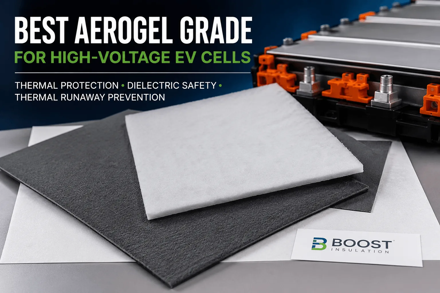
Which Aerogel Grade Is Best for High-Voltage EV Cells?
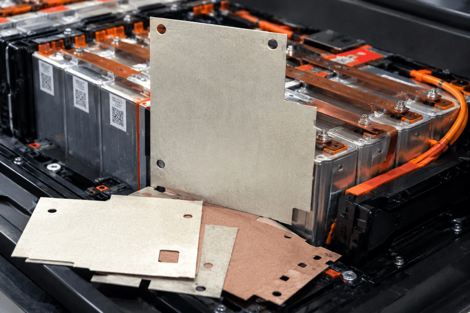
What Is a Mica Insulation Sheet for EV Battery Packs?
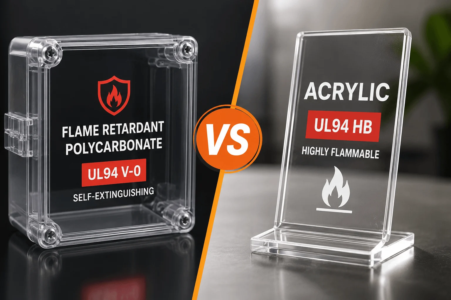
Is Flame Retardant Polycarbonate Better Than Acrylic?
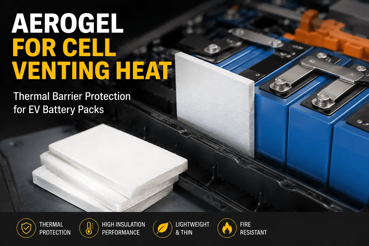
How Does Aerogel Handle Cell Venting Heat in EV Packs?
How Does FR Polycarbonate Compare to Flame Retardant PVC?
 betty wong