Where Should Thermal Barriers Be Placed Between Cells?
Table of Contents
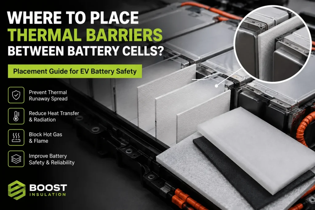
A thermal barrier can have excellent laboratory data and still fail inside a battery module if heat, radiation, or vent gases can travel around it. So where should the barrier actually sit – across the full cell face, only near the hottest zone, between every cell, or around groups of cells? The answer matters because placement determines whether the part becomes a genuine propagation-control component or merely an expensive layer that the failure event bypasses.
| Thermal barriers between battery cells should be placed directly across the dominant cell-to-cell heat-transfer interface, with continuous coverage of the exposed active area and controlled extension toward edges and corners. They must not block pressure-relief vents, intended cooling paths, terminals, or assembly features. Prismatic and pouch cells usually need near-full-face barriers, while cylindrical packs often use row, group, or module partitions. Final placement must be validated under representative compression, venting, electrical connections, and pack geometry. |
Thermal Barrier Placement at a Glance
| Cell Format | Typical Barrier Position | Main Risk | Design Priority |
| Prismatic | Near-full broad-face coverage | Top vent, edges, metal frame | Coverage plus vent shielding |
| Pouch | Across active stack area | Seal damage, swelling, pressure steps | Uniform compression and soft interfaces |
| Cylindrical | Between rows or cell groups | Gas channels, top vent, busbars | 3D vent control and group isolation |
Where Should Thermal Barriers Between Battery Cells Be Placed?
Where Should Thermal Barriers Between Battery Cells Be Placed?
The correct position is the location that interrupts the real propagation path from a failing cell to the next vulnerable cell. In tightly packed prismatic and pouch modules, that path often crosses the large opposing cell faces. In cylindrical arrays, the critical path may pass through narrow contact points, open gas channels, cell holders, busbars, cooling ribbons, or the triangular voids between adjacent cans.
Placement should therefore be determined from a thermal-path map, not from the geometric midpoint of the gap. The barrier needs to reduce direct conduction, obstruct line-of-sight radiation, limit exposure to hot gas and flame, and prevent energy from bypassing through metal structures or uncovered edges. A small central pad may insulate the middle of a prismatic cell while leaving the corners, shoulder, vent region, frame, and cooling plate as faster paths.
For most flat-cell designs, the strongest starting point is near-full coverage of the broad cell-to-cell interface. For cylindrical packs, the strongest starting point is usually a shaped barrier between rows or cell groups, coordinated with vent direction and the cooling architecture. These are design starting points, not universal rules. The representative module must prove that the selected placement meets the required propagation-delay or non-propagation target.
Why Placement of Thermal Barriers Between Battery Cells Matters
Why Placement of Thermal Barriers Between Battery Cells Matters
Thermal conductivity is only one part of the safety equation. A low-conductivity aerogel sheet can resist heat through its thickness, but the module may still propagate through gaps, pressure plates, busbars, bolts, cooling plates, adhesives, or hot vent gas. In contrast, a moderately performing barrier with complete coverage, stable compression, and controlled bypass paths can outperform a premium material installed in the wrong location.
The barrier must also remain where the design placed it. Cells swell, housings vibrate, adhesive ages, foam takes a compression set, and large die-cut parts can creep or shift. End-of-life position and installed thickness matter more than the free-state dimensions measured when the component is new.
Current EV safety development is moving toward system-level thermal-propagation evidence. UN Regulation No. 100 and later thermal-propagation amendment work focus on warning time and hazardous conditions at the battery-system or vehicle level. A material rating or coupon test can support selection, but it cannot establish the result for the complete rechargeable energy storage system.
How Thermal Barriers Between Battery Cells Interrupt Four Heat Paths
How Thermal Barriers Between Battery Cells Interrupt Four Heat Paths
A robust placement review should identify four heat-transfer routes: solid conduction, thermal radiation, hot gas and flame, and structural bypass.
Solid conduction occurs through cell casings, compression plates, holders, adhesives, cooling hardware, and direct cell contact. The barrier should separate the largest opposing hot surfaces and retain enough installed thickness under preload and cell swelling.
Thermal radiation becomes increasingly important as the trigger-cell surface and flame temperatures rise. An uncovered corner or narrow line-of-sight opening can expose the neighboring cell even when most of the face is insulated. Coverage should therefore be checked from the expected hot surface and vent plume, not only from the nominal cell outline.
Hot gas, flame, and ejected particles can cross an open gap much faster than heat conducts through an aerogel core. The intercell barrier may need to work with a top shield, vent guide, mica component, or flame-resistant cover. Structural bypass includes busbars, side plates, cooling plates, fasteners, and module frames that carry energy around the main barrier. These paths normally require separate thermal breaks or electrical-insulation parts.
Six Placement Rules for Thermal Barriers Between Battery Cells
Six Placement Rules for Thermal Barriers Between Battery Cells
Rule 1 – Cover the dominant facing area: For flat cells, cover the active broad face that directly faces the neighboring cell. A small patch is rarely a robust solution because heat can spread laterally through the casing and enter the adjacent cell around the patch.
Rule 2 – Extend toward the edges without loading sensitive features: The barrier should reduce edge radiation and casing-to-casing contact, but it must not stress pouch seals, cover vents, interfere with terminals, or reduce required creepage and clearance.
Rule 3 – Preserve the intended cooling path: Aerogel and other propagation barriers are thermal resistors, not thermal interface pads. Do not place them between a cell and a cold plate where normal operation depends on heat flowing into the coolant, unless the thermal architecture explicitly calls for local isolation.
Rule 4 – Design to the installed compression: Define nominal thickness, compressed thickness, pressure range, tolerance, compression set, and end-of-life swelling. A 2.0 mm pad that operates at 1.2 mm is not equivalent to a 2.0 mm pad that remains at 1.8 mm.
Rule 5 – Keep the pressure-relief path functional: Do not place the barrier over a vent unless the complete venting concept has been validated. Use separate shields and channels to direct flame and hot gas away from adjacent cells.
Rule 6 – Break metallic bypass routes: Busbars, cooling plates, frames, and fasteners can defeat the intercell barrier. Add flame-retardant polycarbonate, mica, insulated hardware, coated films, or geometric separation where the thermal map identifies a bridge.
Thermal Barriers Between Battery Cells in Prismatic Modules
Thermal Barriers Between Battery Cells in Prismatic Modules
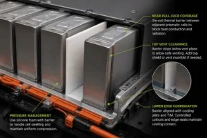
Large prismatic cells normally use a die-cut barrier between adjacent broad faces. Near-full-face coverage is the logical baseline because the facing surfaces provide a large conduction and radiation area. The barrier may extend slightly beyond the active heat-transfer region, provided it does not interfere with rails, cell shoulders, tabs, sensing features, or the top vent.
The upper edge needs a separate review. Many prismatic cells vent upward. A barrier can protect the broad face while stopping below the vent plane, but the exposed top region may still allow a jet flame or high-temperature gas stream to reach the next cell. A vent manifold, under-lid shield, or local mica component may be needed. Covering the vent with a soft barrier without a validated discharge route can increase pressure and redirect the event.
The lower edge must be coordinated with the cooling plate and thermal interface material. The barrier should not fold under the cell or reduce intended cooling contact. Controlled lower-corner radii, cutouts, and edge seals can keep the propagation barrier away from the cold-side interface.
Prismatic cells also swell during life. The barrier can be combined with silicone foam for pressure management, but the stack should avoid hard steps from overlapping films, thick edge seals, liner splits, or full-face adhesive buildup. Nonuniform pressure can change both cell aging and barrier performance.
Thermal Barriers Between Battery Cells in Pouch Modules
Thermal Barriers Between Battery Cells in Pouch Modules
Pouch-cell barriers normally cover the large flat active area of the stack. Because the pouch has little structural stiffness, the component should support uniform pressure and avoid concentrated loads. A rigid insert, adhesive ridge, thick pull tab, or misaligned edge seal can mark or damage the pouch laminate.
The outer pouch dimensions are not enough to design the barrier. Engineering needs the active electrode area, perimeter seal, gas-pocket allowance, tab location, and swelling envelope. Coverage should extend beyond the electrode-stack footprint where useful, but it should avoid the heat seal and any region that the cell supplier identifies as pressure-sensitive.
The component often performs two functions: thermal isolation and stack-pressure management. Aerogel supplies thermal resistance; silicone foam or another compliant layer can absorb thickness variation and maintain preload. The layer order and compression curve should be validated through beginning-of-life and end-of-life conditions. Excessive preload can thin the aerogel, while insufficient preload can create wrinkles, shifting, and air gaps.
Tabs and welded connections create concentrated heat and electrical risks near one end of the pouch. The die-cut profile may need reinforced notches, extended dielectric film, or a separate terminal shield. Every cutout should be treated as a potential radiation window until testing shows otherwise.
Thermal Barriers Between Battery Cells in Cylindrical Packs
Thermal Barriers Between Battery Cells in Cylindrical Packs
Cylindrical packs rarely place one rectangular pad between every pair of cans. The direct contact area between cylinders is small, but open channels between cells can carry radiation, flame, and vent products. Effective designs commonly use shaped partitions between rows, barriers around cell groups, or fire-resistant boundaries at module and pack perimeters.
A row barrier can interrupt a likely propagation direction while preserving liquid-cooling or air-flow channels. A group barrier can confine an event to a controlled number of cells. Perimeter barriers can protect electronics, adjacent modules, and the enclosure wall.
Vent orientation is decisive. Axial venting can create a strong top-side hazard, which makes the under-lid shield or vent manifold as important as the inter-row barrier. Side-wall rupture risk creates a radial exposure path. A thin strip located only at the cylinder tangent may have limited effect if hot gas travels through the voids above and beside it.
Cell holders, nickel connections, busbars, fuses, and cooling ribbons can become heat bridges. Cylindrical modules often require a combined strategy: low-conductivity row barriers, flame-resistant structural insulation, controlled exhaust space, and holder geometry that does not create a continuous hot path.
Should Thermal Barriers Between Battery Cells Cover the Full Face?
Should Thermal Barriers Between Battery Cells Cover the Full Face?
For prismatic and pouch cells, near-full-face coverage is usually the strongest starting point. Full-face does not mean covering every feature. Functional coverage should protect the broad heat-transfer area and vulnerable edges while respecting vents, seals, terminals, locating features, pressure sensors, and cooling interfaces.
Partial coverage may be justified when test data identifies a localized heat path, structural ribs already provide separation, or weight and package constraints require zoning. However, the uncovered region should be supported by thermal mapping and abuse-test evidence. Cost reduction alone is not a sufficient reason to remove coverage.
Tolerance stack-up must also be included. A nominally full-face design can become partial coverage when a cell shifts, the part shrinks, the edge seal consumes too much active area, or die-cut registration drifts. Asymmetric profiles, locating holes, registration tabs, poka-yoke features, and assembly fixtures can prevent incorrect orientation and offset installation.
Where Thermal Barriers Between Battery Cells Should Not Be Placed
Where Thermal Barriers Between Battery Cells Should Not Be Placed
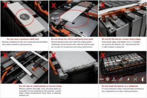
Do not cover a pressure-relief vent unless the complete venting concept has been tested. Blocking or delaying the vent can increase pressure and redirect hot products toward an unprotected area.
Do not place a propagation barrier across the intended cell-to-cold-plate heat path simply because there is space. Normal operating heat must reach the cooling system. Confusing a thermal barrier with a thermal interface pad can increase cell temperature, accelerate aging, and reduce fast-charge performance.
Do not let the barrier contact sharp busbar edges, weld spatter, burrs, or exposed fasteners that can puncture its dielectric skin. A protective polycarbonate film or rigid insulation component may be required.
Do not rely on a small center patch, scattered adhesive dots, or narrow strips without evidence that edge, vent, and metal paths are controlled. Do not install parts with wrinkles, crushed edges, broken encapsulation, loose fibers, or adhesive squeeze-out.
Do not treat the barrier as a substitute for spacing, cooling, sensing, fusing, electrical isolation, controlled venting, or pack-level fire protection. It is one component within a layered safety architecture.
Material Stack for Thermal Barriers Between Battery Cells
Material Stack for Thermal Barriers Between Battery Cells
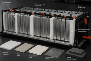
Aerogel is selected when a project needs high thermal resistance in a thin envelope. It is well suited to the direct cell-to-cell interface, but the fragile core often needs encapsulation, handling protection, or mechanical support.
Flame-retardant polycarbonate insulation sheets add puncture resistance, dielectric separation, clean die-cut geometry, and dimensional stability. PC can protect the aerogel surface, isolate metal structures, and form tabs or extensions near terminals. Its primary role is structural and electrical; it should not be treated as an equal substitute for a high-temperature aerogel barrier.
Silicone foam manages gap variation, vibration, preload, and cell swelling. It may sit beside the aerogel or form part of a multilayer assembly. The compression curves must be coordinated so the foam does not force the aerogel below its qualified installed thickness.
Mica is suitable for direct flame, high-temperature jetting, electrical arcing, module boundaries, and under-lid protection. A practical hybrid may use aerogel between cells, PC around electrical and structural features, silicone foam for pressure control, and mica at vent and fire-exposure zones.
Adhesive and Edge Design for Thermal Barriers Between Battery Cells
Adhesive and Edge Design for Thermal Barriers Between Battery Cells
Adhesive improves takt time and part retention, but it changes the thermal and mechanical stack. Full-face pressure-sensitive adhesive increases solid contact and adds a polymer layer across the entire interface. Depending on chemistry and thickness, it can affect thermal resistance, flame behavior, compression, and aging.
Selective adhesive is often preferable. Perimeter strips, small registration zones, or one-sided fixation can hold the part without covering the full thermal area. The adhesive should remain outside vent, terminal, and high-temperature keep-out zones, and it should not squeeze past the barrier edge under assembly pressure.
Encapsulation film reduces dust and improves handling. PET, PI, coated glass fabric, or another film should be selected according to dielectric, temperature, flame, chemical, and flexibility requirements. Film seams and edge seals should not form a stiff frame that transfers heat around the aerogel core.
The drawing should define edge-seal width, overlap direction, adhesive registration, liner split, pull-tab location, orientation, flatness, and contamination limits. The pull tab must be accessible to the operator without forcing the part out of position or damaging the cell.
Die-Cut DFM for Thermal Barriers Between Battery Cells
Die-Cut DFM for Thermal Barriers Between Battery Cells
A thermal barrier is not finished when a material sheet is selected. Conversion quality determines whether the specified coverage and installed condition are repeatable in mass production. Die cutting can crush the edge, expose aerogel dust, distort a thin film, shift adhesive, or create a part that curls during storage.
Prototype parts may be made by digital cutting or flatbed tooling to support rapid design changes. Higher volumes may use rotary, progressive, or multi-station converting when the laminate and geometry permit. Tool clearance, blade condition, support liner, web tension, cutting direction, and dust extraction should be validated for the exact stack.
Critical dimensions usually include overall profile, vent clearance, corner coverage, edge-seal width, adhesive keep-out, tab and notch position, locating features, liner split, and part flatness. Dimensions should be classified by functional risk rather than applying an unnecessarily tight tolerance to every edge.
Packaging is part of the DFM review. Large thin parts can warp, curl, or shift in transit. Packaging should control stack height, compression, humidity, dust, liner orientation, and operator presentation at the assembly line.
How to Validate Placement of Thermal Barriers Between Battery Cells
How to Validate Placement of Thermal Barriers Between Battery Cells
Level 1 – Material and finished-laminate screening. Verify thickness, density, thermal conductivity, high-temperature shrinkage, compression behavior, dielectric strength, flame response, adhesive peel, encapsulation integrity, and particulate release.
Level 2 – Compressed coupon testing. Test the complete stack at representative pressure with a heat-flux source or hot surface. Measure cold-side temperature, time to thresholds, edge leakage, and post-test integrity.
Level 3 – Interface or two-cell testing. Place the converted part between representative cells or instrumented cell simulators. Include the real coverage, edges, vent clearances, adhesives, and metal bypass structures.
Level 4 – Module propagation testing. Trigger the selected cell using the project method and record temperatures, voltage, venting, flame, gas, pressure, and propagation timing. Test worst-case state of charge, production tolerances, aged components, and relevant electrical configuration.
Level 5 – Pack and vehicle validation. Confirm the warning strategy, external hazards, venting, enclosure response, electrical isolation, and post-event safety. Only the integrated test can substantiate a pack-level compliance or non-propagation claim.
Placement should be challenged deliberately. Shift the part within assembly tolerance, use the minimum installed thickness, test the maximum allowed edge gap, include busbars and cooling plates, and evaluate the vent direction most likely to expose the neighboring cell.
Industry Insight: CTP and CTC Change Barrier Placement
Industry Insight: CTP and CTC Change Barrier Placement
Cell-to-pack and cell-to-chassis architectures reduce traditional module walls and increase structural integration. The efficiency gain can remove natural fire breaks and create longer continuous paths through cell rows, pack rails, cooling plates, and structural adhesives.
This changes the barrier strategy from a single repeated intercell pad to a hierarchy of protection. A platform may use cell-face barriers, periodic row or group partitions, module-equivalent fire breaks, under-lid shields, insulated structural members, and controlled vent corridors.
Fast charging and high-energy cell formats further tighten the design window. The pack needs efficient cooling during normal operation but high thermal resistance during failure. Successful systems separate the wanted cold-side heat path from the unwanted cell-to-cell propagation path rather than adding insulation everywhere.
The market is therefore moving from material purchasing to function purchasing. OEMs and pack manufacturers increasingly ask for installed thickness, cold-side temperature curves, propagation delay, vent-path performance, aged-part evidence, and traceable converted components. Suppliers that can provide DFM, multilayer lamination, precision die cutting, rapid samples, and change-controlled production have a stronger role in early design.
RFQ Checklist for Thermal Barriers Between Battery Cells
RFQ Checklist for Thermal Barriers Between Battery Cells
A useful request for quotation should include the cell format and dimensions, chemistry, target state of charge, cell-to-cell gap, active-area and vent drawings, intended cooling path, stack pressure, swelling allowance, barrier location, target installed thickness, and required propagation objective.
Specify the clock and pass criterion: for example, time from trigger-cell thermal runaway to adjacent-cell thermal runaway, maximum protected-cell surface temperature, no flame at a defined boundary, or non-propagation for a stated observation period.
Provide the laminate requirements: aerogel type, protective film, PC reinforcement, silicone foam, mica, adhesive zones, release liner, edge seal, dielectric performance, flame rating, cleanliness, dimensions, packaging, prototype quantity, annual volume, and PPAP or documentation needs.
A capable converter should return more than a price. The response should identify design assumptions, material and process risks, achievable tolerances, recommended adhesive strategy, inspection method, prototype plan, and changes that require revalidation.
How Boost Insulation Supports Thermal Barriers Between Battery Cells
How Boost Insulation Supports Thermal Barriers Between Battery Cells
Boost Insulation supports EV battery insulation projects with aerogel, flame-retardant polycarbonate, silicone foam, mica, films, adhesives, and precision die-cut conversion. The factory positioning is suited to customers that need a complete functional stack rather than an unconverted sheet.
Engineering support can include material screening, laminate design, adhesive zoning, edge encapsulation, pull-tab and liner design, tolerance review, prototype cutting, inspection planning, and production DFM. Boost Insulation also promotes rapid custom sampling and large-scale precision-conversion capacity for battery insulation and thermal-management components.
For a productive review, send the cell or module drawing, target and compressed thickness, pressure range, vent location, cooling interface, material restrictions, flame and dielectric requirements, propagation target, validation method, and estimated annual demand. The first prototype should be treated as the beginning of validation, not as proof of pack compliance.
| Need a placement and DFM review for your cell barrier?
Send Boost Insulation your cell and module drawings, vent locations, compressed thickness, pressure range, material requirements, and propagation target. The engineering team can review barrier coverage, hybrid material options, adhesive zoning, tolerances, prototype tooling, and the RFQ package. |
Frequently Asked Questions About Thermal Barriers Between Battery Cells
Should every battery cell have a thermal barrier?
Not always. Flat high-energy cells often use a barrier at every cell interface, while cylindrical designs may use row or group partitions. The decision should follow the propagation path, cell energy, cooling architecture, and validated safety target.
Should thermal barriers between battery cells cover the vents?
Normally no. Pressure-relief vents must remain functional. Use vent guides, under-lid shields, mica, or other flame-resistant parts to control the hot gas and flame path without obstructing pressure relief.
Can the barrier be placed between the cell and cooling plate?
Only when the thermal architecture intentionally requires isolation. In most designs, normal operating heat must flow to the cold plate, so the propagation barrier belongs across the unwanted cell-to-cell path rather than the desired cooling path.
Is full-face coverage always required?
It is the strongest baseline for prismatic and pouch cells, but final coverage can be zoned when thermal mapping and testing justify it. Vents, seals, terminals, cooling contact, and pressure-sensitive regions remain keep-out areas.
What material is best between cells?
Aerogel is often selected for thin high thermal resistance. PC adds dielectric and puncture protection, silicone foam manages compression and swelling, and mica protects against flame and jetting. Many EV designs use a validated hybrid stack.
Does UL94 V-0 prove a barrier will stop thermal propagation?
No. UL 94 is a small-flame material test. It does not reproduce cell thermal runaway, hot particle impact, high heat flux, vent gas, or the complete pack geometry. Propagation performance requires representative module and pack testing.
How should adhesive be placed?
Use only the adhesive needed for assembly stability. Perimeter or zoned adhesive can reduce thermal and compression changes compared with full-face bonding. Validate peel, aging, squeeze-out, flame behavior, and installed thickness.
What files are needed for a die-cut prototype?
Provide a 2D drawing, cell and module layout, active area, vent and terminal keep-outs, compressed thickness, pressure range, material stack, adhesive zones, tolerances, test target, prototype quantity, and expected annual volume.
Technical References
- UNECE, UN Regulation No. 100, Revision 3 – rechargeable electric energy storage system safety and thermal propagation. Source
- UNECE, 05-series thermal-propagation amendment documents, including five-minute warning and hazard provisions. Source
- UL Solutions, Combustion (Fire) Tests for Plastics – UL 94 V, 5V, and VTM test descriptions. Source
- Becher et al., Preventing Thermal Propagation in Battery Packs Using a Novel Thermal Barrier, 2021. Source
- Nambisan et al., Characterization of Commercial Thermal Barrier Materials for Battery Applications, 2023. Source
- Read et al., Performance of Interstitial Thermal Barrier Materials on Large Prismatic Cell Propagation, 2024. Source
- Wong et al., Nanofiber Aerogel for Thermal-Runaway Propagation Mitigation in High-Energy Modules, 2024. Source
- Boost Insulation, EV battery insulation and thermal-management manufacturing capabilities. Source
Related Posts:
How Does a Mica Insulation Sheet Compare With FR4 Boards?
How Do You Prevent Aerogel Pads From Shifting in EV Packs?
How Do You Select Aerogel Thickness Between Cells?
How Does Cell-to-Cell Thermal Barrier Improve ESS Safety?
How Do You Choose a Flame Retardant PC Supplier?

Why Choose a China Factory for Die-Cut Insulation?
 betty wong