
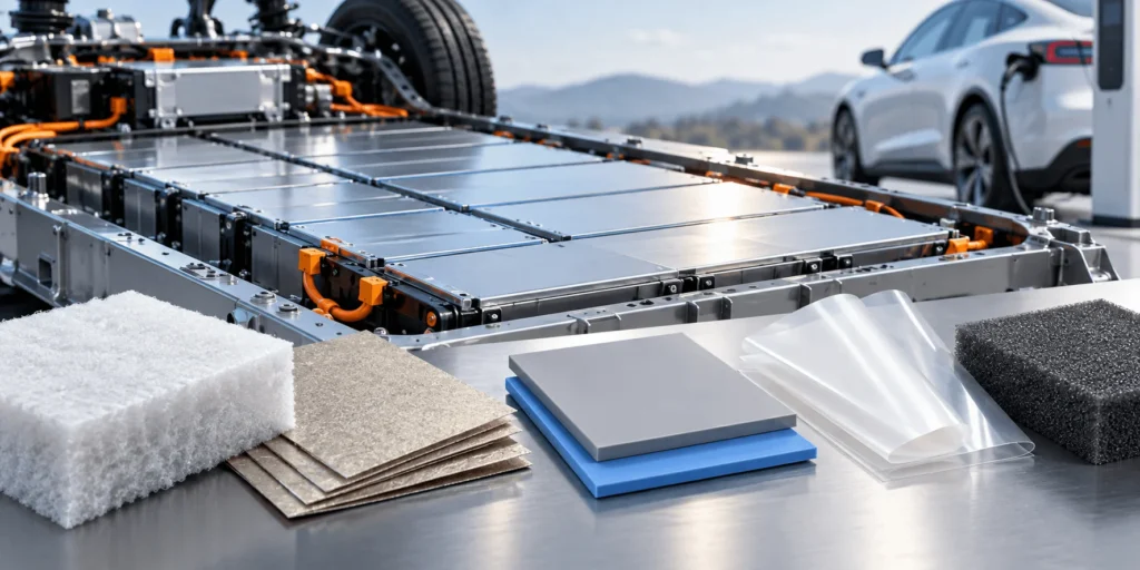
Best EV Battery Insulation Materials: Aerogel, Mica, Thermal Pads & More
Should an EV battery material move heat away, or stop heat from moving at all? In a modern battery pack, the answer is often both – but in different places. Choosing the wrong material can improve one thermal path while quietly weakening electrical isolation, thermal-runaway protection, compression control, or assembly reliability.
For areas that must block heat while preserving electrical isolation, aerogel generally provides the strongest insulation-per-millimeter balance in EV battery packs. For interfaces that must conduct heat to a cooling plate while remaining electrically insulating, a thermally conductive dielectric pad or gap filler is the better choice. Mica is preferred where high-temperature fire resistance and dielectric durability dominate, while flame-retardant PC/PET films suit thin electrical barriers. In practice, the best EV design usually combines these materials in a layered system rather than relying on one material everywhere.
The Short Answer: Match the Material to the Direction You Want Heat to Move
The phrase “heat and insulation” can hide two opposite engineering goals. Around power electronics, cold plates, and cell-to-cooling interfaces, engineers want low thermal resistance so heat leaves the component quickly. Between adjacent cells, around module end plates, beneath pack covers, and near passenger-facing structures, engineers may want high thermal resistance so abnormal heat does not propagate. Electrical insulation may be required in both cases. That is why selecting one material only from its thermal-conductivity number is a common specification error.
A useful rule is to define the heat-flow objective before selecting the material. If heat should cross the layer, compare thermal impedance, conformability, dielectric breakdown, compression pressure, aging, and bond-line control. If heat should be blocked, compare thermal resistance at the real compressed thickness, high-temperature integrity, dielectric behavior, flame/thermal-propagation performance, edge stability, and mechanical retention. The word “best” only makes sense after this direction is clear.
| EV location / goal | Preferred material family | Why it fits | Main caution |
| Cell-to-cell thermal propagation delay | Aerogel barrier | Very high thermal resistance in thin, lightweight constructions | Compression, edge integrity, handling, adhesive and installed thickness must be controlled |
| Module/pack fire barrier | Mica or high-temperature composite | Strong dielectric and high-temperature structural performance | Stiffness/brittleness, thickness, and forming limits |
| Battery-to-cold-plate heat transfer | Thermally conductive dielectric pad or gap filler | Moves heat while maintaining electrical isolation | Bond-line thickness, contact pressure, voids, aging |
| Busbar / terminal isolation | FR PC/PET film, insulating paper, mica | Thin dielectric barrier with precise geometry | Verify flame rating at actual thickness; protect against cut-through |
| Cell compression / vibration | PU or silicone compression foam | Controls force, tolerance and vibration | Not automatically a thermal-runaway barrier |
Why One Material Cannot Optimize Every EV Thermal and Electrical Function
Battery packs combine electrochemistry, high voltage, cooling, structural compression, vibration control, sealing, crash protection, and fire safety in a very small volume. A material that is excellent in one dimension can be deliberately poor in another. A high-conductivity thermal pad is valuable when a cell or power module must reject heat, but that same conductivity is undesirable as a cell-to-cell thermal barrier. A low-conductivity aerogel barrier can delay lateral heat transfer, but it should not be placed across a designed cooling path without understanding the thermal penalty.
The same trade-off appears electrically. Graphite and metal foils spread heat efficiently, yet they are electrically conductive and therefore need isolation from high-voltage nodes. Thin polymer films provide excellent dielectric separation with very little thickness, but they are not automatically fire barriers or thermal-runaway blockers. Mica tolerates severe heat and provides strong electrical insulation, but it is typically less compressible than foam and does not replace a thermal interface material at a cold plate. A robust EV stack therefore assigns each layer a job.
Engineering insight: The best EV insulation strategy is usually a heat-path architecture, not a material ranking. First decide where heat must travel during normal operation and where heat must not travel during an abnormal event. Then assign conductive, dielectric, compressive, and fire-barrier layers accordingly.
1. Aerogel: Best When You Need Maximum Thermal Isolation in Limited Space
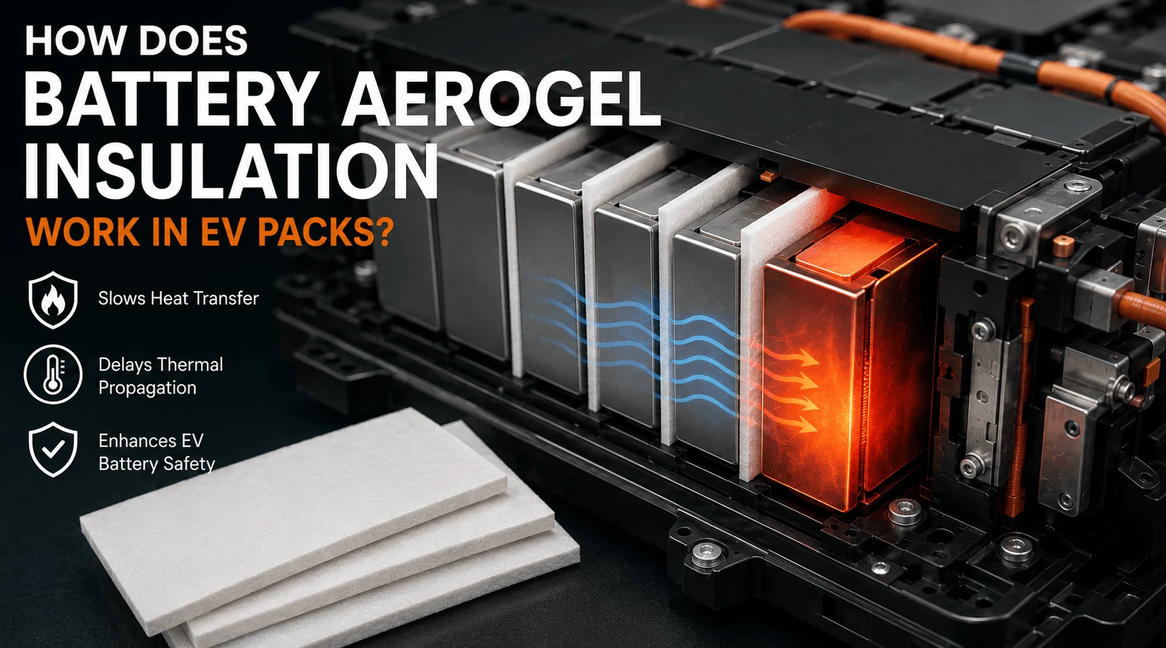
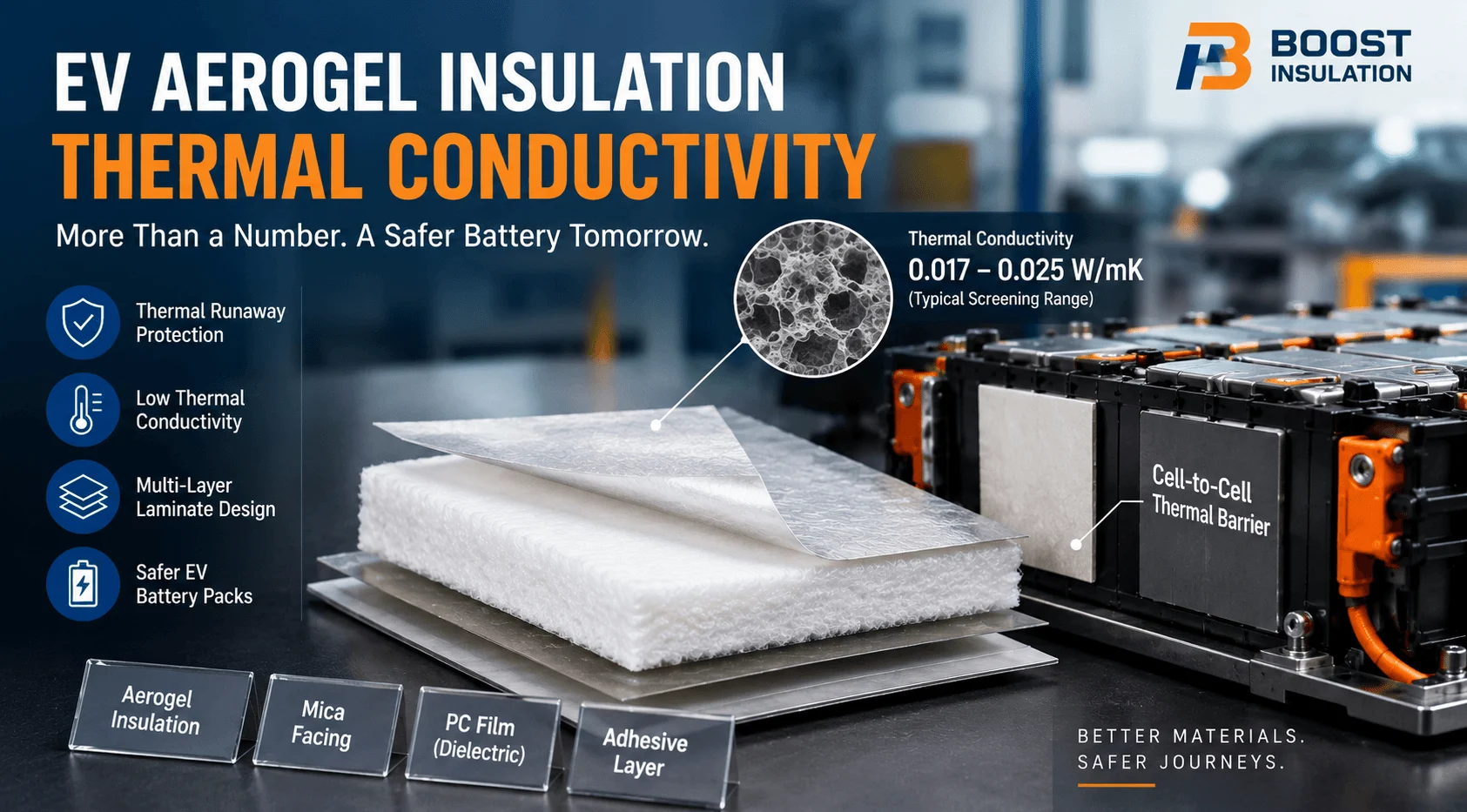
Aerogel is the strongest candidate when the design objective is to slow heat transfer through a thin, lightweight barrier. In EV batteries, flexible aerogel composites are used as cell-to-cell or cell-to-module thermal barriers because their porous structure can deliver very low thermal conductivity while occupying far less space than many conventional insulators. Commercial EV-grade aerogel barriers are also engineered around thickness, compression response, handling, and high-temperature behavior rather than being treated as a fragile laboratory material.
This makes aerogel especially relevant in prismatic and pouch architectures where every millimeter competes with cell volume. It can be placed between cells, near module end plates, around selected propagation paths, or as part of a multilayer firewall. In these positions the goal is not to keep the battery cool during normal charging; the goal is to reduce heat flux into a neighboring cell or protected structure long enough for the overall battery safety strategy to work.
Aerogel does, however, require conversion discipline. The finished part may need a protective film, adhesive, carrier, scrim, edge seal, locating feature, or compressible companion layer. Compression changes effective thickness, contact, and thermal resistance. Poorly designed cutouts can create local thermal bridges. Uncontrolled dust or damaged edges can create assembly problems. For a production program, the correct question is therefore not simply “What is the conductivity of the aerogel sheet?” It is “What thermal and mechanical performance does the converted part retain at the installed thickness after vibration, thermal cycling, and cell swelling?”
Aspen Aerogels describes its EV thermal barriers as engineered around thermal conductivity, thickness, and compression response, which reflects the direction of current automotive practice: the barrier is a tuned component, not a commodity sheet. This is also why DFM review matters before tooling. A 1 mm nominal material that operates at a different compressed thickness in the pack should be evaluated in the state in which it actually functions.
2. Mica: Best for High-Temperature Fire Barriers and Durable Dielectric Protection
Mica is often the better answer when the primary risk is severe temperature, flame exposure, arc resistance, or long-term dielectric separation. Mica-based sheets and laminates are widely used around battery modules, pack lids, busbars, high-voltage interfaces, and fire-protection structures because the mineral base retains insulating value at temperatures where many organic films soften, shrink, or carbonize.
Compared with aerogel, mica is usually selected less for the lowest possible heat transfer per millimeter and more for robust high-temperature survivability, dielectric strength, stiffness, and flame-barrier behavior. In a battery pack that distinction matters. A cell-to-cell layer may be optimized for delaying propagation in a narrow gap, while an upper pack shield or module end barrier may need to maintain physical integrity under flame, hot gas, particles, and mechanical load.
Mica also converts well into defined shields, frames, barriers, and punched components, but brittleness, edge quality, hole-to-edge distance, bend requirements, and lamination choices must be considered during DFM. If the part will be assembled robotically, designers should also evaluate flatness, pickup surface, release-liner design, and whether a thin support film improves handling without undermining high-temperature performance.
3. Thermally Conductive Dielectric Pads and Gap Fillers: Best When Heat Must Reach the Cooling System
At the battery-to-cold-plate interface, inverters, onboard chargers, DC/DC converters, and other power electronics, the thermal objective reverses. Here the material should reduce interfacial thermal resistance and move heat into a heat sink or liquid-cooled structure while still electrically isolating the energized component. Ceramic-filled silicone pads, reinforced thermal insulators, gap fillers, and thermally conductive adhesives are designed for this function.
A useful example is a fiberglass-reinforced silicone thermal insulator such as Henkel’s BERGQUIST SIL PAD family, which combines thermal conduction with electrical isolation. Henkel also positions gap fillers for EV batteries as materials that fill uneven interfaces and transfer heat efficiently into the cooling system. These products illustrate a core design principle: electrical insulation does not always mean thermal insulation. A dielectric layer can be intentionally thermally conductive.
When specifying a thermal interface material, avoid ranking candidates on bulk W/mK alone. Bond-line thickness, contact resistance, softness, assembly pressure, pump-out or migration risk, thermal cycling, surface wet-out, and the flatness of the mating surfaces can dominate system performance. A softer 3 W/mK gap filler that completely wets a variable gap may outperform a nominally higher-conductivity material that leaves voids or requires damaging pressure.
This distinction is commercially important for die-cut suppliers. Pre-cut thermal pads can reduce dispensing complexity, improve takt time, and provide controlled placement, but the die-cut geometry must match the true contact area and compression window. For liquid gap fillers, die-cut dams, spacers, insulating frames, or locating components may still be required around the interface.
4. Flame-Retardant PC and PET Films: Best for Thin Electrical Isolation and Assembly-Friendly Barriers
Flame-retardant polycarbonate and PET films are strong choices when electrical insulation, dimensional precision, thinness, and clean high-volume conversion are more important than extreme thermal isolation. Typical locations include busbar insulation, module sidewalls, cell wrapping, terminal barriers, sensing and BMS areas, enclosure liners, and thin separators between conductive structures.
These films are attractive because they can be die-cut into complex geometries, laminated with pressure-sensitive adhesive, folded or formed in selected designs, and supplied on release liners for automated assembly. UL94-rated grades can add flame-retardant performance, but the UL rating should be verified at the actual thickness and construction being purchased. Electrical creepage and clearance still depend on geometry; a V-0 label does not replace high-voltage design rules.
For many EV parts, PC/PET film is the most cost-efficient way to add a controlled dielectric barrier without consuming the volume required by thicker fire or thermal barriers. It becomes even more useful as part of a laminate – for example, a thin film can protect an aerogel surface, carry adhesive, improve handling, or create a clean interface for automated placement.
5. Compression Foams and Elastomers: Best for Force Control, Vibration Isolation, and Gap Management
Compression foams are sometimes described as insulation materials, but their most valuable EV function is mechanical. Pouch and prismatic cells change dimension with state of charge, aging, temperature, and swelling. A compression pad can help manage force, absorb tolerance stack-up, reduce vibration, and maintain alignment. Rogers, for example, emphasizes compression-set resistance and stress-relaxation behavior for battery pads because consistent force across life is central to pack reliability.
Foam can also contribute thermal resistance and sealing, but it should not automatically be treated as a substitute for an aerogel propagation barrier or a mica firewall. The better approach is to decide whether the layer’s primary job is force management, thermal isolation, or both. Hybrid constructions – such as aerogel plus a resilient foam, or mica plus a compressible layer – are often more predictable than asking one material to satisfy incompatible mechanical and thermal targets.
Material Comparison: What Each Option Is Actually Best At
| Material | Blocks heat | Conducts heat | Electrical insulation | Fire / high-temp | Compression / conformity | Typical EV role |
| Aerogel composite | Excellent | Low | Good* | Very good* | Tunable; grade-dependent | Cell barriers, end-plate barriers, propagation control |
| Mica laminate | Very good | Low to moderate | Excellent | Excellent | Low to moderate | Fire shields, end plates, HV insulation, pack barriers |
| Thermal pad / gap filler | Poor as insulation | Excellent | Good to excellent* | Grade-dependent | Excellent | Cold plates, power electronics, gap filling |
| FR PC/PET film | Limited | Low | Excellent | Good by rated grade | Low | Busbars, terminal barriers, wraps, liners |
| PU / silicone foam | Moderate | Low | Good* | Grade-dependent | Excellent | Compression, sealing, vibration, tolerance control |
| Graphite / metal foil | Poor | Excellent | No | Good to excellent | Low | Heat spreading; requires dielectric isolation |
*Performance depends on the exact grade, construction, thickness, reinforcement, and test method.
The comparison above is intentionally qualitative. Exact values vary dramatically by grade, density, thickness, reinforcement, adhesive, filler content, and test method. For engineering release, always compare supplier TDS data and validate the converted stack under your actual pressure, temperature, voltage, and aging conditions.
How to Choose the Best Material by EV Application
Between adjacent prismatic or pouch cells
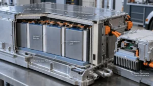
If the priority is delaying thermal propagation with minimal thickness, an engineered aerogel barrier is usually the first material to evaluate. If the assembly also needs controlled cell pressure, combine thermal isolation with a compression-management layer rather than over-compressing the aerogel. Where severe flame exposure is expected, a mica or high-temperature composite can be added at module boundaries or other critical surfaces.
Between the battery module and cooling plate
Use a thermally conductive dielectric gap pad, gap filler, or adhesive. Here lower thermal resistance is desirable. Specify the operating gap, flatness tolerance, target compression pressure, dielectric requirement, rework requirement, and expected thermal cycling. Do not put a high-performance thermal insulator across this interface unless the system intentionally needs to restrict heat flow.
Around module end plates and side structures
End plates can become bypass paths for heat. A local aerogel or other low-conductivity barrier can reduce this path, while mica or flame-resistant laminates can add high-temperature structural protection. The correct architecture depends on preload, end-plate material, cell swelling, vent direction, and how the module is restrained.
Busbars, terminals, and high-voltage interconnects
Thin dielectric films, formed PC barriers, insulating papers, or mica parts are typically more suitable than soft thermal barriers. The priorities are dielectric strength, creepage/clearance support, puncture resistance, dimensional stability, flame rating, and precise cut geometry. Adhesive-backed die-cut films can simplify assembly when peel strength and aging are validated on the actual substrate.
Pack lid and passenger-facing firewall
High-temperature barrier integrity becomes more important. Mica, high-temperature composites, aerogel laminates, ceramic papers, or multilayer fire barriers may be used depending on allowable mass, thickness, venting, hot-particle exposure, and required delay. A single datasheet temperature number is not enough; flame, gas flow, mechanical retention, and edge paths must be considered.
Inverter, onboard charger, and power electronics
Thermally conductive electrical insulation is usually the goal. Reinforced silicone thermal pads, ceramic-filled interface materials, thermally conductive adhesives, and ceramic substrates are common options. These components generate concentrated heat continuously, so the material must conduct heat rather than trap it.
Seven Engineering Criteria That Matter More Than the Material Name
- Heat-flow objective: Define whether the layer must conduct, spread, or block heat. This single decision eliminates many unsuitable materials immediately.
- Installed thickness and compression: Nominal sheet thickness is not the operating condition. Evaluate compressed thickness, pressure, tolerance stack-up, and end-of-life dimensional changes.
- Electrical requirement: Specify working voltage, dielectric withstand, insulation resistance, creepage/clearance geometry, puncture risk, and whether the barrier contacts a sharp metal edge.
- Abnormal-event requirement: For thermal runaway, define the expected heat flux, flame or hot-particle exposure, duration, vent-gas path, neighboring-cell criterion, and the required structural retention of the barrier.
- Mechanical life: Consider vibration, shock, compression set, stress relaxation, swelling, abrasion, and whether the part can shift or wrinkle during assembly and vehicle life.
- Manufacturing process: A material that performs in a laboratory but cannot be cut, laminated, picked, placed, inspected, or traced at takt time is not an automotive solution.
- Cost at the finished-part level: Compare yield, nesting efficiency, adhesive, carrier film, scrap, tooling, labor, automation, quality inspection, and warranty risk – not raw sheet price alone.
Industry Insight: EV Safety Rules Are Pushing Materials Toward Multifunctional Stacks
The regulatory direction is becoming stricter. China’s GB 38031-2025 traction-battery safety standard was published in March 2025 and took effect on July 1, 2026, replacing GB 38031-2020. The updated framework strengthens battery safety requirements, including thermal-propagation expectations. For suppliers and OEM engineers, the strategic implication is clear: passive materials can no longer be treated as isolated commodity parts. They are elements of a pack-level safety architecture that must work together with cell chemistry, venting, BMS logic, cooling, enclosure design, and structural restraint.
At the same time, cell-to-pack and cell-to-chassis designs reduce module-level hardware and increase packaging efficiency. That trend can reduce the number of traditional brackets and covers while increasing the functional burden on thin converted materials. A single die-cut part may now need to provide dielectric isolation, tolerance accommodation, flame resistance, assembly retention, and localized thermal control. This is one reason multilayer laminates are becoming more important.
Another shift is the move from material-level specifications to component-level validation. Engineers increasingly care about heat flux through a real compressed stack, the temperature on the protected side, adhesive retention after aging, particle control, and whether the barrier remains in place after vibration. A thermal conductivity value measured on pristine bulk material is useful, but it cannot describe every failure mode of a converted EV part.
Why a Hybrid Material Stack Often Beats a Single ‘Best’ Material
A practical EV design often uses five different thermal and insulation functions in the same local area. Consider a prismatic cell module. A thin aerogel barrier can reduce cell-to-cell heat transfer. A compression pad can manage swelling and stack force. A mica or high-temperature composite can protect the module boundary. A PC/PET die-cut film can isolate a busbar or metal frame. A thermally conductive gap filler can transfer normal operating heat to the cold plate. Each material is doing the job it is physically suited to do.
Trying to replace all five functions with one material usually creates compromises. Making an insulator more thermally conductive helps cooling but hurts thermal isolation. Making a thermal barrier softer may improve conformity but reduce dimensional stability. Adding thick fire protection may improve safety but reduce volumetric energy density. The engineering task is therefore to minimize the total stack thickness, mass, cost, and assembly complexity while meeting each local requirement.
Procurement insight: Ask suppliers to quote the finished functional stack, not just raw materials. A slightly higher sheet price can be cheaper at the pack level if the converted laminate eliminates manual adhesive application, reduces scrap, improves robotic placement, or combines two parts into one.
A Practical Material-Selection Workflow for EV Battery and Power-Electronics Teams
For an engineering or sourcing team evaluating materials, the fastest route to a useful shortlist is to provide the converter with application data rather than asking for a generic “best material.” Start with the location and failure mode. Then define the thermal direction, electrical requirement, thickness envelope, mechanical pressure, temperature range, fire/propagation target, substrate, and assembly method. This turns material selection from a catalog exercise into an engineering decision.
For example, if you say “we need a 0.8-1.2 mm cell-to-cell barrier for a prismatic module, compressed under a defined preload, with PSA on one side for assembly, and we need the neighboring cell to remain below our propagation criterion during a specific test,” a supplier can evaluate aerogel construction, protective film, adhesive, edge geometry, and manufacturability. If you only ask for “1 mm aerogel“, most of the system-level risk remains unresolved.
Likewise, for a cold-plate interface, share the nominal and maximum gap, flatness, contact area, allowable compression pressure, dielectric requirement, cooling-plate coating, rework expectation, and desired thermal resistance. This allows the supplier to compare thermal pad, gap filler, or adhesive options based on real interfaces rather than marketing conductivity numbers.
Die-Cutting and Lamination Details That Can Change Thermal Performance
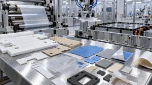
Material selection gets most of the attention, but conversion details often decide whether the part works on the production line. Die-cut geometry can introduce thin ligaments that tear, narrow bridges that create weak points, or cutouts that expose a direct heat path. Adhesive can improve placement but add thermal resistance or alter high-temperature behavior. Carrier films can improve handling but change stiffness and compression. Release liners can determine whether a robot can pick the part cleanly.
For aerogel, the converter should control edge integrity, dust, dimensional tolerance, lamination pressure, and part orientation. For mica, tooling should minimize cracking and edge damage. For thin PC/PET films, dimensional stability, static control, liner selection, and adhesive registration become important. For thermal pads, compression and cut-edge cleanliness matter because thickness and contact determine thermal performance. These are not secondary manufacturing details; they are part of functional design.
A strong DFM review therefore looks at nesting and material yield together with performance. It may recommend changing a radius, moving a slot, increasing a web width, adding a pickup tab, splitting a large part, or laminating two materials before die cutting. Small geometry changes can reduce scrap and improve automation without changing the pack’s thermal concept.
What to Put in an RFQ for EV Thermal and Insulation Parts
- Application location: cell-to-cell, module end plate, busbar, cold plate, pack lid, inverter, OBC, DC/DC converter, or other.
- Thermal objective: conduct heat, spread heat, block heat, or delay thermal propagation.
- Target thickness and allowable compressed thickness range.
- Operating pressure or compression percentage, including tolerance stack-up and expected cell swelling.
- Electrical requirements: dielectric withstand, insulation resistance, creepage/clearance constraints, and working voltage.
- Fire or thermal-runaway requirements: test method, exposure direction, duration, protected-side temperature target, and vent-gas environment.
- Operating and storage temperature, humidity, coolant, electrolyte, and chemical exposure.
- Required flame rating or material certification, including the exact thickness covered by the certification.
- Adhesive requirements: one-side/two-side PSA, peel target, substrate, reworkability, liner style, and automation needs.
- Drawing format, dimensional tolerances, CTQ dimensions, hole/slot geometry, and flatness requirements.
- Annual volume, SOP timing, prototype quantity, PPAP/APQP expectations, lot traceability, and packaging requirements.
Providing these inputs early reduces back-and-forth and allows meaningful comparison between aerogel, mica, thermal pads, flame-retardant films, foam, and hybrid constructions. It also helps the converter propose cost-down opportunities before the material and geometry are locked.
How Boost Insulation Supports EV Material Selection and Precision Conversion
Boost Insulation is positioned as more than a sheet-material supplier. The company combines EV battery insulation materials with DFM, lamination, slitting, CNC/precision die cutting, cleanroom-controlled production, rapid prototyping, and automotive quality workflows. Its current portfolio includes aerogel insulation, mica solutions, UL94 V-0 PC/PET films, thermal pads and gels, silicone sheets, insulating papers, foams, and adhesive laminates – the same families that engineers typically combine in battery and power-electronics stacks.
For buyers, the value of using a converter with multiple material families is that the comparison can happen at part level. Instead of forcing every problem into one material, the engineering team can evaluate whether a design should use an aerogel-only barrier, mica laminate, adhesive-backed PC film, thermally conductive pad, or a multilayer stack. Boost states that it supports DFM, 48-hour prototyping, IATF 16949 and ISO 9001 quality systems, cleanroom production, APQP/PPAP workflows, and high-volume traceability.
That capability is most useful early in NPI. Sending a DXF/DWG/PDF plus the thermal, electrical, compression, and assembly requirements allows the converter to review manufacturability before tooling. The result should be a prototype that represents the production construction – including adhesive, liner, protective film, and stacking sequence – so that fit and performance testing are relevant to the eventual mass-production part.
Frequently Asked Questions
Is aerogel the best insulation material for EV batteries?
Aerogel is one of the best options when the goal is high thermal isolation in a thin, lightweight cell or module barrier. It is not the best material for every EV location. At a cooling interface, a thermally conductive dielectric material is usually more appropriate; for severe fire exposure or rigid dielectric shielding, mica may be preferred.
What material can conduct heat but still electrically insulate?
Thermally conductive dielectric pads, gap fillers, silicone sheets, ceramic-filled polymers, and ceramic substrates can transfer heat while providing electrical isolation. Selection depends on thermal resistance, dielectric strength, gap size, pressure, mechanical stress, and manufacturing process.
Is mica better than aerogel for EV batteries?
Neither is universally better. Aerogel is usually favored for low thermal conductivity and thin thermal-runaway barriers. Mica is favored for high-temperature fire resistance, dielectric durability, and structural barrier applications. Many packs use both in different locations or in a multilayer construction.
Can a thermal pad replace an insulation barrier between cells?
Usually not if the design goal is to block cell-to-cell heat transfer. Most thermal interface pads are designed to conduct heat, which is the opposite function. A thermally conductive pad may be appropriate where heat must reach a cooling surface, while a low-conductivity barrier is used where propagation must be slowed.
Does UL94 V-0 mean a material is a thermal-runaway barrier?
No. UL94 V-0 is a flammability classification under a specific test method. It does not by itself prove that a material can stop or delay thermal propagation in a battery pack. Thermal-runaway protection should be validated at the component or pack level using the required exposure, geometry, compression, and failure criteria.
What is the most important data to send a die-cut insulation supplier?
Send the drawing plus the material function, thickness envelope, operating compression, electrical requirement, temperature and fire exposure, substrate, adhesive/liner requirement, annual volume, and validation standard. These inputs allow the supplier to recommend a construction rather than simply quote a raw sheet.
Final Recommendation
If your EV design needs one simple rule, use this: choose aerogel where you need to stop heat, choose a thermally conductive dielectric interface where you need to move heat, choose mica where extreme heat and fire-barrier integrity dominate, and choose PC/PET film where thin electrical isolation dominates. Then use compression foams, adhesives, carriers, and structural features to make those materials work reliably in assembly and over vehicle life.
The highest-performing EV packs do not search for a universal “best insulation material.” They control heat paths deliberately. That means separating normal cooling from abnormal-event containment, then converting the right materials into precise, stable, production-ready parts.
Project CTA: Need to compare aerogel, mica, thermal pads, or flame-retardant dielectric films for a battery pack or power-electronics project? Send Boost Insulation your drawing, thickness envelope, thermal objective, dielectric requirement, compression range, and annual volume. The engineering team can review material options and DFM, then prepare production-representative samples for validation.
Related Posts:
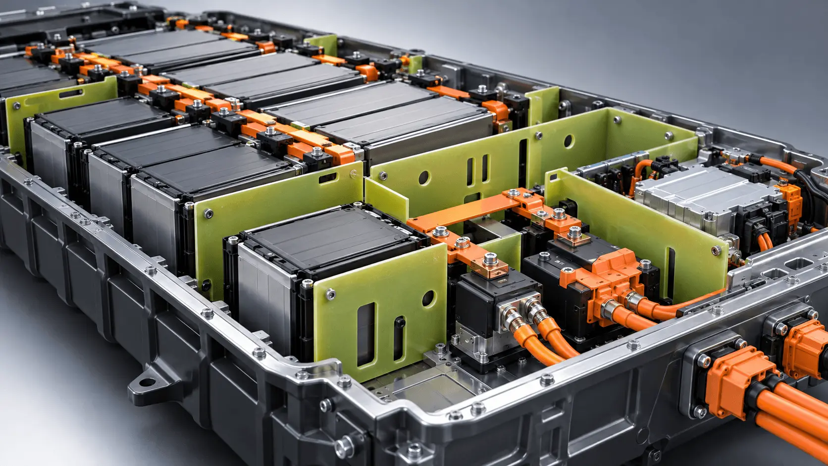
Why Use FR4 as Rigid Insulation in EV Battery Packs?
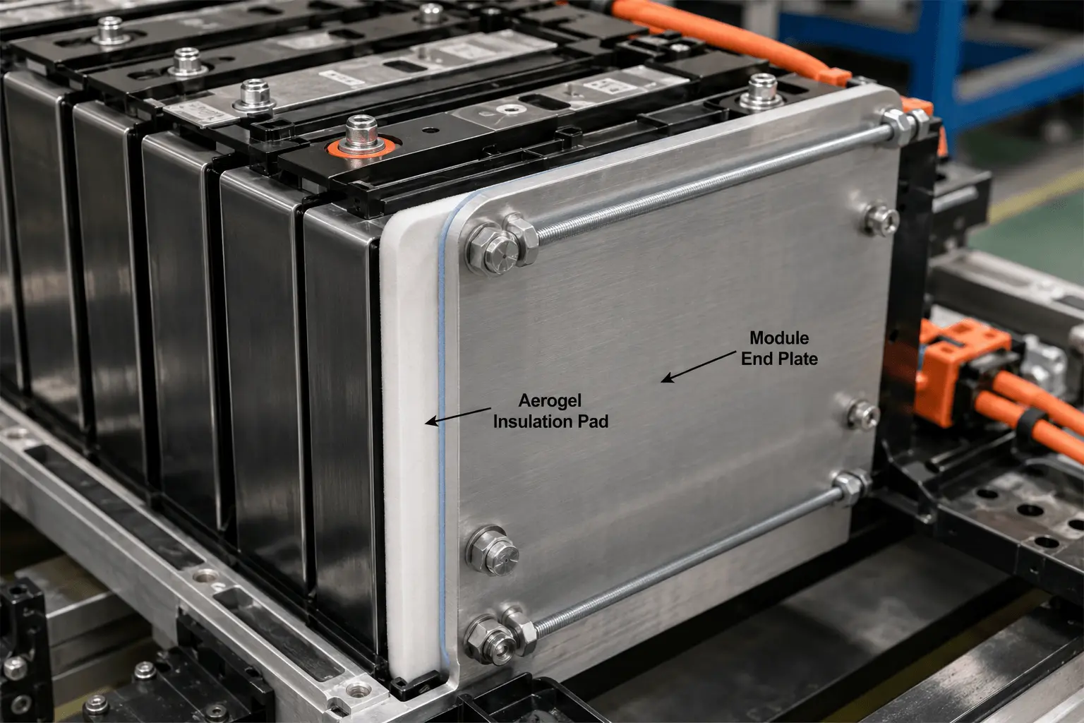
How Is Aerogel Used Near EV Battery Module End Plates?
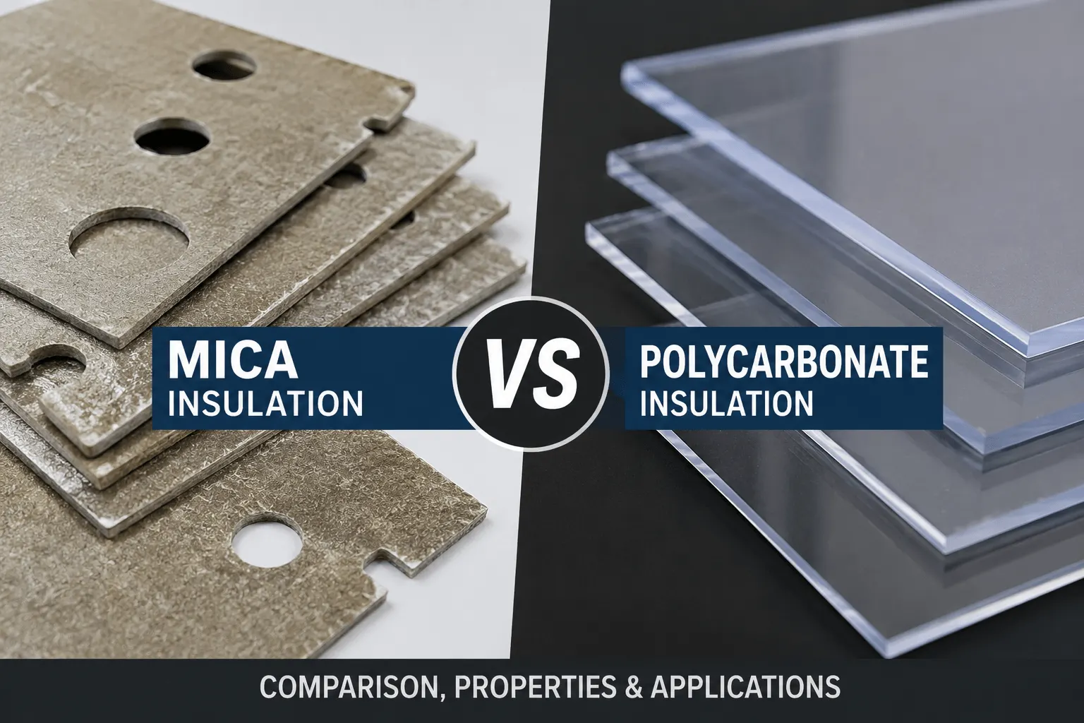
How Does Mica Insulation Compare With Polycarbonate?
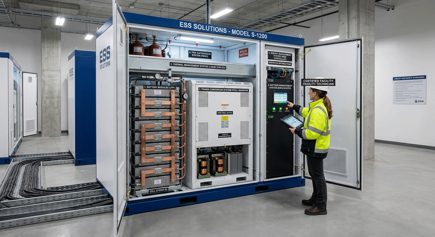
What Are the Main Components Inside an ESS Storage Solution?
How Does Battery Aerogel Insulation Work in EV Packs?
What Density Is Best for Battery Aerogel Insulation?
 betty wong
