
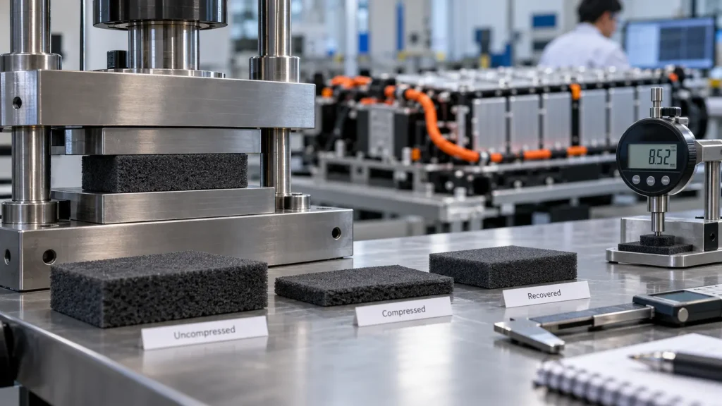
How Do You Test Silicone Foam Recovery in EV Battery Pads?
Table of Contents
A silicone foam pad may appear to rebound after compression, but visual recovery does not establish whether it meets an EV battery module’s long-term gap-management requirements. A pad can regain much of its thickness while showing altered reaction force, delayed recovery, or persistent deformation after thermal exposure. The result also depends on how long the pad was held, how it was unloaded, and when the recovered thickness was measured. For battery engineers, recovery becomes useful only when the measurement conditions are defined and reproducible.
To test silicone foam recovery in EV battery pads, identify the material and specimen construction, condition each sample, and measure its initial thickness using a defined method. Compress it to the specified gap or strain, maintain that condition for an agreed time and temperature, then unload and allow a defined recovery interval. Measure the recovered thickness and calculate the specified compression-set or recovery metric using the selected method’s definitions. Record the complete test history, compare aged and cycled specimens where required, and separately assess reaction-force retention and the performance of the finished pad in the actual battery assembly.
Engineering takeaway: A recovery percentage without the compression history, recovery interval, measurement procedure, and material grade is not a transferable acceptance result. Thickness recovery is not a substitute for force retention.
What Does Foam Recovery Mean in an EV Battery Pad?
Silicone foam provides compliance in selected pouch- and prismatic-cell interfaces, module end regions and tolerance-compensation features. As a battery assembly changes dimension, the installed pad may undergo further compression or partial unloading. Recovery describes dimensional rebound after unloading under defined conditions; it does not establish whether the pad maintains the required installed pressure.
Define the decision before testing: grade screening, incoming inspection, converted-part qualification or module correlation. Material tests support consistent comparison. Module tests include actual gaps, adhesives, restraints and contacts. Boost’s EV battery cell insulation pad selection guide addresses why recovery matters; this article addresses how to measure and report it.
Compression Recovery, Compression Set, and Stress Relaxation
These measurements must not be collapsed into one claim about “elasticity.” For a compressed pad, a dimension measured after unloading differs from the force measured while its thickness is held fixed. Compression-force-deflection (CFD) data provide another view: how force changes as the pad is compressed over the design range.
Table 1 — Related Tests and What They Establish
| Property | Test boundary condition | Measured output | What it does not prove |
| Thickness recovery | Load, unload, then wait a defined interval | Recovered dimension or a stated recovery metric | Long-term installed contact force |
| Compression set | Method-defined compression and recovery sequence | Residual deformation calculated using that method | Dynamic fatigue life or complete module durability |
| Stress relaxation | Hold displacement approximately constant | Reaction-force change versus time | Unloaded thickness recovery |
| CFD | Measure force during controlled deflection | Loading curve across a specified strain range | Force after months of sustained load |
| Force retention | Defined compression and environmental history | Retained force at an agreed comparison point | A universal result for all gap conditions |
| Compression cycling | Repeat a defined loading/unloading program | Changes in force, hysteresis, and dimensions | Actual battery life without correlation |
An elastomeric cellular material may show a small compression set yet lose force under sustained compression. Conversely, immediate rebound can be incomplete even when subsequent recovery continues. Engineers should qualify the relevant properties separately, rather than use a supplier’s single low-set figure as a universal proxy for pressure stability.
Which Standard Applies to Silicone Foam Compression Testing?
Select the method only after confirming the material form, grade and purpose. ASTM D395-18(2025) covers compression set of rubber and identifies constant-force and constant-deflection approaches, including a method considering hardness. ASTM D1056-20 is a specification for sponge or expanded rubber, covering relevant physical-property requirements and referenced testing procedures. These documents serve different roles. Product datasheets for silicone foams may report compression set or CFD under ASTM D1056 conditions, but buyers must inspect the exact grade and footnotes.
A particularly important scope limitation concerns ISO 1856:2018. Its publicly stated scope applies to latex and polyurethane foams thicker than 2 mm. It should therefore not be casually specified as a directly applicable default method for silicone foam. If a customer adopts a modified or analogous procedure, label it explicitly as a customer-defined method and document deviations; do not imply conformity to an inapplicable standard.
Table 2 — Test Reference Selection
| Reference | Primary role | Applicability check | Reporting caution |
| ASTM D395-18(2025) | Rubber compression-set methods | Confirm suitability for the specific elastomer and specimen | Identify Method A, B, or C and the selected conditions |
| ASTM D1056-20 | Flexible cellular sponge/expanded rubber specification | Confirm grade, class, suffix and invoked test | Do not cite “D1056 tested” without the property procedure |
| ISO 1856:2018 | Compression-set methods for defined flexible cellular materials | Published scope specifies latex and polyurethane foams above 2 mm | Not a blanket silicone-foam certification method |
| Supplier test procedure | Grade-specific characterization | Confirm sample, compression, conditioning and calculation | Proprietary results may not equal standardized results |
| Customer assembly protocol | Installed-pad functionality | Link fixtures and limits to actual module geometry | Identify deviations from material-level standards |
Rogers’ technical discussion illustrates why apparently similar supplier values can differ: foam families may use different specimen sizes, unloading intervals, calculations, and referenced test methods [5]. Those manufacturer examples are not universal EV battery test conditions. Final laboratory instructions should cite the actual licensed standard edition and customer specification.
Define the Test Objective Before Preparing Samples
For material screening, compare representative samples using one procedure. For lot release, agree on sampling and reporting. For prototype validation, examine the actual converted thickness and construction. For module correlation, use a representative gap and contact footprint.
A suitable objective is: “Compare recovered thickness and reaction-force change after a specified compressed thermal exposure”. State whether the result concerns dimensions, force or both before choosing fixtures and acceptance criteria.
How Should Silicone Foam Specimens Be Prepared?
Identify supplier, foam grade, lot, thickness, density if relevant, skin, adhesive, carrier film and liner. Follow the selected method’s specimen geometry when applicable; do not assume every thin die-cut pad qualifies as a standard specimen. Conditioning, orientation, count and edge condition must be documented.
If finished components are too small or irregular, test parent-sheet coupons for material characterization and the converted parts using a separately described application method. Label the reports accordingly rather than claiming standard conformity for a modified specimen.
How Should Initial Foam Thickness Be Measured?
Initial thickness (t0) controls the recovery calculation. Soft foam compresses under a measuring foot, so specify instrument contact pressure, dwell, specimen support and locations. Record conditioning and whether the result is an average or a specified-point measurement.
For laminated pads, distinguish foam-only thickness from total composite thickness. Use the same dimensional definition before and after compression. Capture relevant local variation rather than choosing measurement points after seeing the results.
How Do You Set Compression Strain or Fixture Gap?
A fixed-gap test sets compressed thickness (ts) through platens or spacers; constant-force testing imposes a different boundary condition. For an illustrative fixed-gap setup, engineering strain can be expressed as (t0 − ts) / t0, subject to the chosen protocol’s measurement definitions.
Use minimum, nominal and maximum battery gaps, assembly tolerances and cell swelling to choose relevant compression conditions. Do not assume a catalog percentage represents the installed assembly. Verify contact area, spacer dimensions and platen alignment.
Why Do Hold Time and Temperature Matter?
Time under compression and temperature influence viscoelastic deformation, recovery and aging, with grade-specific effects. A short ambient hold therefore differs from prolonged exposure while compressed even at the same strain.
Specify when timing begins, temperature control location, exposure medium, and whether clamping continues during transitions. Do not convert an accelerated test into an asserted vehicle lifetime without demonstrated correlation. Check all these inputs before comparing supplier data.
How Should the Foam Be Unloaded and Allowed to Recover?
Specify the exact recovery-clock start: clamp release, specimen removal or another documented event. Note whether unloading occurs hot or after cooling, keep handling consistent and prevent stretching during the recovery interval.
Immediate rebound and later recovery can be different engineering quantities. If both matter, measure at separately specified intervals. Never compare supplier results obtained after different waiting periods without highlighting the difference.
How Do You Measure Recovered Thickness?
Measure recovered thickness (tr) after the defined interval using the prescribed contact pressure, gauge and measurement locations. Document curling, wrinkles, asymmetric recovery or damage that could affect the measurement.
Retain individual sample values and note instrument repeatability where relevant. Wide scatter may reflect specimen variation or timing and gauge differences; investigate the procedure before attributing it to foam formulation.
How Is Compression Set Calculated and Reported?
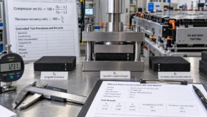
A widely used fixed-deflection expression is compression set (%) = 100 × (t0 − tr) / (t0 − ts), where t0 is original thickness, ts is the specified compressed spacer gap, and tr is thickness after the prescribed recovery interval. This expression describes deformation relative to the imposed deflection; it must only be associated with a named standard method after verifying that method’s definitions and requirements. Rogers identifies this form in its ASTM D1056 product-testing discussion [5].
A simple illustrative, nonstandard thickness-recovery ratio can instead be defined as 100 × tr / t0. These two percentages use different denominators and must not be labeled as equivalent. No example value is an acceptance criterion. If a customer chooses to report both, print both formula definitions, units, recovery timing and the dimensions actually used. Applying a formula without recording the boundary conditions creates precision on paper without engineering comparability.
Table 3 — Controlled Test Procedure and Records
| Step | Parameter to define | Reason | Record to retain |
| Specimen | Grade, lot, thickness, skin and laminate | Establishes what was tested | Specimen identification |
| Conditioning | Environment and duration | Stabilizes starting state | Conditioning log |
| Initial measurement | Foot force, locations and t0 | Establishes baseline | Individual measurements |
| Compression | Force or gap, imposed deflection | Defines test boundary | Fixture setup and ts |
| Hold | Time, temperature, medium | Defines exposure history | Time/temperature log |
| Release | Unloading sequence and clock start | Controls recovery timing | Release timestamp |
| Recovery | Interval and environment | Influences tr | Recovery log |
| Result | Method, formula and statistics | Enables meaningful comparison | Calculations and deviations |
Why Is Thickness Recovery Not Force Retention?
An EV battery compression pad commonly remains installed under a constrained gap. In that state the engineering concern can be force loss while the thickness is held approximately constant. This is stress relaxation, which requires force-versus-time measurement under defined displacement and environmental conditions. Unloaded recovered thickness does not measure that force directly.
For example, two hypothetical foams can return to similar dimensions after unloading while showing different reaction forces at the same installed compression after aging. That is a qualitative illustration, not a claim about any supplier’s material. The correct acceptance plan may therefore require both a compression-set metric and a separate residual-force or stress-relaxation criterion, linked to the cell manufacturer’s pressure limits.
How Does CFD Help Interpret Pad Recovery?
A CFD test captures force across an agreed deflection range. A loading curve and unloading curve can differ; the enclosed hysteresis reflects energy dissipation during that specific sequence. Compare curves using the same rate, compression range, specimen form and temperature. A single CFD point may hide an undesirable force rise near maximum compression or a weak response after the gap reopens.
The useful battery-specific question is whether the force remains within the allowed range at minimum, nominal and maximum installed gaps, including the effects of tolerances, swelling and aging. Do not infer a lifetime force window by extrapolating from one initial curve. Where the pad carries a laminated dielectric film, inspect whether the construction affects measured stiffness or creates localized stress.
How Should Compression Cycling Be Added?
Define the compressed and released positions, loading rate, dwell at each end, cycle count, temperature and whether the pad can recover freely between cycles. Measure thickness and force at agreed checkpoints. Not every change is deterioration: first-cycle conditioning and hysteresis may produce different responses from later cycles, while some irreversible dimensional changes can accumulate.
A cycle count is meaningful only together with the stroke, loading profile and environment. Battery cell swelling is not necessarily a symmetric, completely reversible repeated compression cycle; cell chemistry, temperature and aging can introduce permanent dimensional changes. A representative module profile should be derived from the actual cell and assembly design, with separate tests for conditions the laboratory cycling sequence cannot simulate.
How Does Heat Aging Change the Comparison?
Differentiate heat aging with compression held from heat aging without compression, since the resulting stress and recovery histories differ. Document whether the sample is cooled while clamped, when it is unloaded, and when it is measured. Record aging duration and environment rather than stating vaguely that the foam was “heat tested.”
Table 4 — Aging and Cycling Test Matrix
| Condition | Question answered | Measurements | Interpretation caution |
| Unaged compression/recovery | Baseline dimensional response | t0, ts, tr, set/recovery metric | Does not establish service life |
| Heat aging without load | Effect of temperature exposure | Thickness and optional CFD | Not equivalent to compressed aging |
| Heat aging under fixed gap | Deformation under simultaneous time, heat and strain | Set and recovered thickness | Recovery interval must match |
| Constant-gap force hold | Reaction-force stability | Force versus time | Not a compression-set measurement |
| Defined compression cycling | Response to repeated movement | Force curves, thickness, damage | Cycle history must be specified |
| Finished-pad stack test | Functional performance with adhesive and geometry | Force, fit, gap and electrical checks | Assembly-specific findings |
Does Thickness, Density, or Foam Structure Change the Test?
Density and cellular construction influence performance but do not alone predict recovery. Thickness, skin, adhesive backing and the available contact footprint also affect specimen equivalence. Report these factors before comparing grades.
For thin or irregular production pads, use an appropriate parent-sheet coupon for material characterization and a separate finished-part test. Do not substitute one result for the other without demonstrating representativeness.
How Do Adhesive and Lamination Affect Recovery?
Boost publicly describes foam, adhesive and film lamination for EV battery module insulation components [6]. In an adhesive-backed pad, define whether liners remain attached, whether adhesive contacts the fixture and whether a carrier restricts lateral movement. These choices alter composite thickness or loading conditions.
Test bare foam to characterize the material and the final laminate to qualify the purchased construction. Lamination does not necessarily worsen recovery, but its effects cannot be assumed absent.
Raw Foam or Finished Die-Cut Pad: Which Should You Test?
Both may be useful, depending on the decision. Raw-material tests support grade screening and supplier consistency. Finished die-cut pad inspection verifies dimensions, tolerances, liner behavior, adhesive registration and local features. Application tests show whether the part works at the installed compression and contact footprint. Each level should trace back to the approved material grade and revision.
Table 5 — Material Versus Finished-Pad Acceptance
| Acceptance item | Raw foam evidence | Converted-part evidence | Battery assembly evidence |
| Identity and thickness | Grade, lot and measured sheet | Finished thickness and construction | Installed stack dimension |
| Compression set/recovery | Defined material method | Representative part or validated coupon | Relevance to movement and free gap |
| CFD/force retention | Grade screening curve | Composite force response | Minimum/maximum allowed cell pressure |
| Aging/cycling | Material change after exposure | Laminate integrity and dimensions | Performance in the constrained fixture |
| Adhesive/film effects | Not represented by bare foam | Registration, bond and layer structure | Retention during installation and cycling |
| Electrical function | Grade-specific dielectric evidence, if required | Finished insulation geometry | Electrical checks under actual assembly conditions |
As the overview of EV battery insulation materials explains, a battery pad may be mainly mechanical rather than a primary dielectric barrier. In that case, do not invent electrical qualification requirements; instead document which layer or neighboring component provides electrical isolation. Conversely, a multifunction insulation pad needs the electrical and mechanical validation that its actual responsibilities demand.
How Does Recovery Testing Relate to Cell Swelling?
Define minimum, nominal and maximum module gaps using cell-supplier data, assembly tolerances and expected dimensional change. Assess both further compression and partial unloading; do not assume swelling is fully reversible or foam behaves as an ideal spring.
Recovery information helps describe dimensional response, but force-versus-gap requirements decide whether the pad is suitable. A pad that rebounds well may become too stiff at maximum compression or lose force during prolonged installation.
What Must the Supplier Test Report Include?
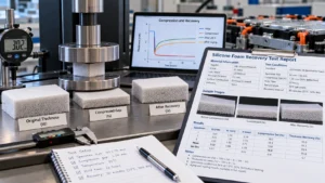
A report should allow another engineer to reproduce and interpret the test. Include the exact test reference and version, any deviations, material grade, lot, specimen size, thickness method, surface construction, conditioning, compression condition, hold environment, unloading sequence, recovery interval, individual results and calculation definition. For aged or cycled specimens, include the full preceding history.
Table 6 — Minimum Useful Recovery Test Report Fields
| Report field | Required detail | Why it matters | Frequent omission |
| Material identity | Supplier, grade, lot, revision | Traceability | “Silicone foam” only |
| Specimen definition | Size, thickness, skin, adhesive and count | Comparability | Unspecified construction |
| Method identification | Standard edition or customer protocol | Interpretation | “ASTM tested” only |
| Measurement setup | Contact force, locations, fixture | Repeatable dimensions | Undefined gauge pressure |
| Compression history | Gap/strain or force, time, temperature | Defines exposure | Compression percentage alone |
| Recovery conditions | Unloading event, wait, environment | Defines measured tr | No recovery interval |
| Output | Raw t0/ts/tr, equation, per-sample values | Auditable calculation | Mean percentage only |
| Qualification decision | Acceptance rule, deviations, follow-up | Connects data to function | No pass/fail basis |
Required fields depend on the selected standard and purchasing agreement; this table is a suggested engineering report structure, not a verbatim reproduction of any proprietary standard.
How Should Recovery Acceptance Criteria Be Set?
Tie acceptance to the battery’s functional requirement and a fixed procedure. Specify whether the limit concerns compression set, recovered thickness, force retention, CFD, or several properties. Include temperature, aging history, compression boundary, recovery interval, sampling and decision rule.
Derive limits from cell pressure requirements and validated program evidence—not from a generic foam label. Define how suspect results are investigated and when assembly-level retesting is required.
How Do You Troubleshoot Inconsistent Recovery Results?
Check the test setup before assuming a material defect. Was a different surface skin tested? Did the specimen remain warm during recovery? Did the caliper apply more pressure? Did another technician start the recovery clock earlier? Was the adhesive liner removed from one sample but not the other? Were fixture spacers measured and aligned?
Table 7 — Recovery Test Troubleshooting
| Unexpected observation | Possible cause | Investigation | Corrective review |
| Lower reported recovered thickness | Shorter recovery interval or heavier gauge pressure | Audit timestamps and gauge method | Standardize timing and measurement |
| Large specimen scatter | Thickness or skin variation | Compare locations and specimen records | Define sampling and surface orientation |
| Different supplier set values | Different denominators or standard conditions | Compare full procedures and equations | Retest under one agreed method |
| Good rebound, low assembly force | Stress relaxation or force-curve change | Run constant-gap force test | Add force-retention criteria |
| Worse result after lamination | Composite constraint or measurement definition | Compare bare and finished specimens | Qualify the finished construction |
| Damage after cycling | Geometry, fixture or material behavior | Inspect edges and compression footprint | Review DFM and cycle boundary conditions |
What Are the Most Common Testing Mistakes?
Avoid fifteen common mistakes: (1) confusing recovery with compression set; (2) quoting an unqualified percentage; (3) mixing standards; (4) changing gauge pressure; (5) omitting conditioning; (6) leaving strain undefined; (7) missing hold time; (8) missing temperature; (9) inconsistent unloading; (10) variable recovery timing; (11) inferring force retention from thickness; (12) ignoring relaxation; (13) ignoring cycling; (14) equating bare foam with a laminate; and (15) setting criteria without battery requirements.
Each makes the result less reproducible or less relevant. Control the conditions, preserve raw dimensions and qualify the specific function required.
Six Industry Insights for Battery Foam Recovery Qualification
Insight 1 — History is part of the result. Compression duration, temperature and recovery interval travel with every reported percentage; sourcing comparisons must account for them.
Insight 2 — Distinct properties require distinct tests. Thickness recovery and compression set cannot replace constant-gap force-retention or CFD evidence.
Insight 3 — Converting changes the test object. Skins, adhesives, films and die-cut geometry require representative finished-part qualification.
Insight 4 — Aging differs from cycling. Heat without load, heat under strain and repeated motion probe different risks; no single schedule establishes service life.
Insight 5 — Module gap governs the decision. Useful recovery performance must coexist with the specified reaction-force window throughout the stack range.
Insight 6 — Documented supplier data prevent false disputes. Controlled procedures, lots and raw measurements separate test variation from material variation.
Engineering Test Checklist for EV Battery Silicone Foam Pads
Before releasing a test plan, confirm:
- Material/specimen: supplier, grade, lot, density if specified, free thickness, tolerance, skin, adhesive, films, geometry, specimen count and conditioning.
- Procedure: method and edition, thickness gauge/contact pressure, measurement positions, force or fixture gap, alignment, compression strain, hold time, temperature and release sequence.
- Recovery/data: clock start, waiting interval, recovered thickness, formula definition, deviations, individual values, summary statistics and report.
- Additional qualification: stress relaxation, CFD, force retention, heat aging, compression cycling and post-test inspection as applicable.
- Module correlation: installed gap range, cell swelling, pressure limits, stack tolerances, finished-pad acceptance and assembly validation.
RFQ Checklist for Custom Silicone Foam Compression Pads
Send the pad’s PDF/DXF/DWG and available 3D assembly, installation function, candidate foam grade, nominal thickness/tolerance, profile and holes, adhesive/liner, minimum/nominal/maximum gap, compression range, cell swelling allowance, permitted force window, recovery test method and conditions, hold temperature/time, recovery interval, cycling/aging plan, prototype quantity, annual volume and inspection expectations.
If the foam grade is unknown, supply assembly geometry + compression envelope + force limits + environment + validation targets rather than requesting a vaguely defined “high-recovery foam.”
How Boost Insulation Can Support the Development Process
Boost’s EV battery module insulation page describes material selection, drawing/DFM review, die cutting and foam/adhesive/film lamination [6]. Its cell-pad selection and silicone-foam/aerogel articles provide application context [7,8]. These public statements do not establish in-house capability for every ASTM or ISO recovery procedure.
A practical path is Drawing and Compression Requirements → Material/DFM Review → Prototype Pads → Customer or Qualified-Lab Testing → Assembly Validation. The battery designer defines cell pressure limits and acceptance; the supplier documents the approved grade and construction before production.
Frequently Asked Questions
1. How do you test silicone foam recovery in EV battery pads?
Measure a conditioned specimen’s initial thickness, compress it to a defined gap or strain, and hold it under the selected time and temperature conditions. Unload using the stated procedure, wait the prescribed recovery interval, and measure its recovered thickness. Apply the selected method’s defined calculation, report individual results and all test conditions, and compare the outcome with application-specific criteria. Evaluate retained force separately if the installed pad must maintain cell pressure.
2. What is the difference between compression recovery and compression set?
Compression recovery describes dimensional rebound following a defined release and waiting interval. Compression set expresses residual deformation using a test-method-specific definition and calculation. These quantities may be related but are not interchangeable labels. The measured dimensions, compressed reference gap and selected denominator matter. When reviewing datasheets, request the method edition, test history, recovery interval and formula instead of comparing two percentages that may have been calculated differently.
3. Which standard should be used for silicone foam compression recovery testing?
Choose a test reference only after confirming the exact foam construction and purpose. ASTM D395 covers rubber compression-set methods, while ASTM D1056 is a flexible cellular sponge/expanded-rubber specification containing relevant material test requirements. ISO 1856:2018 publicly identifies latex and polyurethane foams above 2 mm as its scope, so it should not automatically be treated as a silicone-foam method. If a customer uses a modified procedure, identify and document it without asserting unsupported standard conformity.
4. How long should silicone foam recover before thickness is measured?
There is no universal waiting period for all silicone foam grades and test objectives. Use the recovery interval specified by the applicable test method, supplier procedure or approved customer protocol, then report that interval with the result. Immediate rebound and delayed recovery may yield different thicknesses. For qualification, ensure all comparison samples follow the same unloading and timing sequence, and introduce additional measurement points only when their engineering purpose is defined.
5. How do temperature and hold time affect silicone foam recovery?
Both determine the specimen’s compression history and can influence permanent deformation, delayed recovery and viscoelastic behavior. The direction and magnitude of change depend on the exact grade and construction. A result after a short ambient hold cannot automatically predict recovery after prolonged compressed heat aging. Specify temperature control, exposure time, recovery conditions and measurement timing, and compare materials only under equivalent procedures or clearly documented differences.
6. Does good thickness recovery mean good force retention?
No. Thickness recovery is measured after unloading, while force retention concerns the reaction force maintained at an installed compression, often during a constant-gap hold. A foam can recover close to its starting dimension and still deliver a different force after aging. EV battery engineers should consider separate stress-relaxation and compression-force-deflection evaluations, with acceptance criteria related to the cell manufacturer’s permitted pressure range and the module’s actual gap.
7. How should compression cycling and heat aging be included in testing?
Define the cycling end positions, rate, dwell, count and temperature, and measure force and thickness at selected checkpoints. For heat aging, distinguish specimens held compressed from those aged freely. Specify cooling, unloading and recovery procedures before comparison. Neither an arbitrary cycle count nor one elevated-temperature exposure proves battery service life. Test profiles should represent identified application risks, and any claimed lifetime correlation requires separate evidence.
8. Should engineers test raw silicone foam or finished die-cut battery pads?
Raw foam specimens are useful for comparing material grades and tracking supplier consistency. Finished die-cut pads may include surface skins, adhesives, insulating films, cut features and a different compression footprint, so their behavior may not match the bare material. Use both test levels when the qualification decision requires them, and add an assembly-representative fixture if cell pressure or dimensional stability is safety-relevant. Clearly identify which construction each result represents.
Conclusion: Qualify the Measurement, Not Just the Percentage
A meaningful silicone foam compression recovery test depends on specimen construction, controlled thickness measurements, defined compression and temperature, unloading, recovery time and a correctly identified calculation. For EV battery pads, combine dimensional data with CFD, force retention, aging, cycling and installed-gap verification.
For a custom project, send Boost Insulation your pad drawing, gap/compression range, target force window, recovery conditions, adhesive construction, prototype volume and annual demand for a material and DFM review. Validate the selected finished component before production release.
Related Posts:

How Can Buyers Verify Aerogel Grades for EV Battery Use?
What Makes Flame Retardant Polycarbonate Ideal For Batteries?
What is UL94 V0? Guide to Flame Retardant PC Film Testing
Should EV Battery Aerogel Pads Wrap or Split at Corners?
How Does PC Insulation Protect EV Battery End Plates?

What Temperature Can a Mica Insulation Sheet Withstand?
 root
