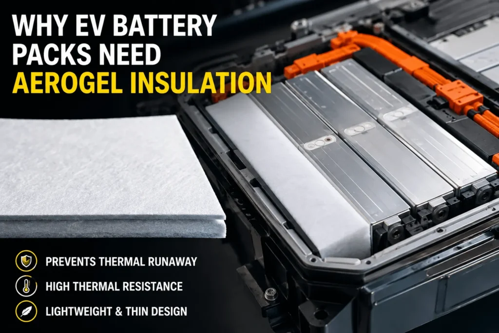
Why Do EV Battery Packs Need Aerogel Insulation Today?
Table of Contents
A battery pack can perform perfectly for thousands of miles—until one damaged or defective cell releases heat faster than the pack can remove it. When cell spacing is measured in millimeters, what keeps that local event from becoming a module-wide failure? That question is why aerogel insulation has moved from a specialist material to a critical design option for today’s EV battery packs.
EV battery packs need aerogel insulation because modern designs store more energy in less space, while thermal runaway can transfer intense heat from one cell to the next. A thin aerogel barrier adds high thermal resistance between cells and critical structures, slowing heat flow and helping the pack’s cooling, venting, warning, electrical-isolation, and containment systems prevent or delay hazardous propagation.
Engineering Takeaways
- Aerogel is needed when a pack must add high thermal resistance without sacrificing excessive cell spacing, mass, or volume.
- It is a passive barrier, not a coolant or extinguisher; it must work with cooling, venting, electrical isolation, warning, and structural containment.
- The qualified unit is the finished die-cut laminate under installed compression, followed by representative module and pack abuse testing.
- In 2026, stricter system-level safety expectations are increasing demand for architecture-specific, fully documented barrier components.
The Short Engineering Answer
Aerogel is needed today because EV battery safety has become a race between the rate at which a failing cell releases energy and the rate at which the surrounding pack can absorb, redirect, or isolate that energy. A conventional air gap may be too small, a polymer film may provide electrical insulation without enough thermal resistance, and active cooling may be optimized for normal driving rather than a sudden abuse event. Aerogel addresses the missing function: high thermal resistance in a thin, lightweight barrier.
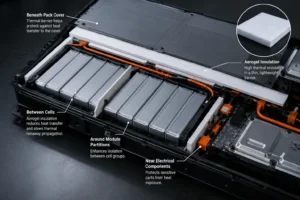
That function is particularly valuable between prismatic or pouch cells, around module partitions, beneath pack covers, and near vulnerable electrical or structural components. The barrier does not repair the initiating cell and it does not replace a battery management system. It changes the heat-transfer path so the neighboring cell, busbar, cover, or enclosure heats more slowly.
The word today matters. Pack architecture, charging rates, cell size, safety expectations, and vehicle integration have all changed. A barrier concept that was optional in a spacious module can become essential in a tightly integrated cell-to-pack design.
Why the Need Is Growing Now
- More energy is being packaged into less volume. Automakers continue to pursue range, cabin space, and lower pack mass. Larger cells, thinner module frames, reduced inactive material, and cell-to-pack or cell-to-chassis structures improve volumetric efficiency, but they can also reduce the passive distance available between a hot cell and its neighbor. When geometry offers less separation, the insulation layer must provide more thermal resistance per millimeter.
- Fast charging increases the importance of aging-aware safety design. Fast charging is not automatically unsafe, but high current, repeated cycling, temperature gradients, and cell aging can change the conditions under which faults develop. The newly effective Chinese standard GB 38031-2025 adds a fast-charge-cycle safety test for applicable batteries, illustrating how regulators are looking beyond a new pack’s initial condition. Barrier materials must therefore be assessed after compression, cycling, vibration, humidity, and thermal aging—not only when the part is new.
- Thermal propagation expectations are becoming stricter. UN Regulation No. 100 Revision 3 formalized thermal-propagation concepts and occupant-warning requirements for rechargeable energy storage systems. China’s GB 38031-2025, effective July 1, 2026, raises the thermal-diffusion requirement from a warning-centered approach to no fire and no explosion at pack or system level, while retaining warning and smoke-hazard provisions. These requirements apply to complete systems, not to one sheet of material, but they increase the value of well-engineered passive barriers.
- Pack architectures are more multifunctional. The same narrow space may need electrical isolation, thermal resistance, controlled pressure, vibration damping, vent clearance, flame resistance, and automated assembly. A bare insulation sheet rarely performs all of these functions. Aerogel increasingly appears as the thermal layer within a converted stack that also uses flame-retardant polycarbonate, silicone foam, film, adhesive, or mica.
- The cost of late safety redesign is high. A thermal barrier added after module tooling is frozen can force changes to cell spacing, cooling plates, end plates, covers, adhesives, and pack height. Early aerogel DFM and validation reduce the risk of discovering after abuse testing that a vent path bypasses the barrier or that assembly compression removed too much effective thickness.
How Aerogel Creates Thermal Resistance
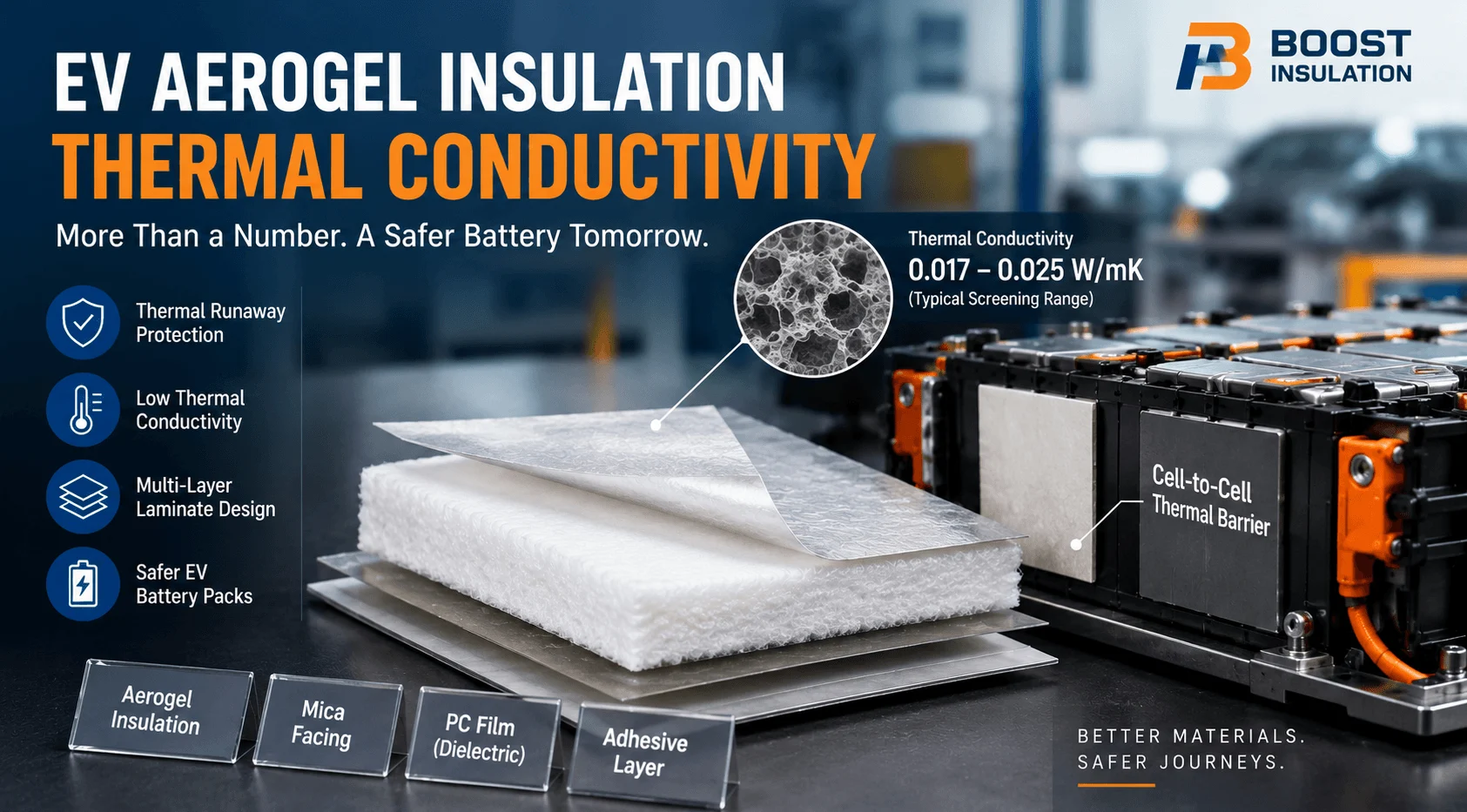
Silica aerogel contains a sparse solid skeleton and a very high volume of nanoscale pores. Heat has difficulty moving through the limited solid network, and the tiny pores restrict gas motion. In simplified terms, the barrier increases thermal resistance because it combines low through-thickness thermal conductivity with a defined installed thickness.
For a flat layer, thermal resistance increases with thickness and decreases as thermal conductivity rises. This explains why a thicker aerogel layer can delay heat transfer longer, but it does not mean that thickness alone determines performance. Compression changes retained thickness and density films and adhesives add new heat paths edge seals can become thermal bridges and radioactive heat transfer becomes more important at high temperatures.
Battery-grade aerogel is therefore usually a reinforced composite rather than a fragile laboratory monolith. Fiber reinforcement, scrims, PET or polyimide films, pressure-sensitive adhesive, release liners, and sealed edges make the material practical to handle and assemble. Each added layer improves manufacturability but can change the final part’s thermal, dielectric, mechanical, and flame behavior.
The correct engineering unit is the finished, installed laminate. A raw-core data sheet is useful for screening, but the module sees the entire construction under pressure, temperature, aging, and abuse.
What Happens During a Cell Failure
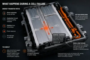
A cell entering thermal runaway can transfer energy to surrounding parts through several parallel paths: direct conduction across the cell face, conduction through metallic frames and cooling hardware, radiation from hot surfaces, flame exposure, and hot vent gas or particles. A barrier that blocks only one path may still allow propagation through another.
Aerogel primarily reduces through-thickness heat transfer across the protected face. By slowing the neighboring cell’s temperature rise, it can keep that cell below its own failure threshold during the most intense stage of the event. Even when propagation is not prevented indefinitely, added time can support warning, vehicle evacuation, electrical isolation, active cooling, pressure relief, and emergency response.
Experimental research supports this system-dependent view. Tests using different aerogel-felt thicknesses found that increasing thickness improved the delay of thermal-runaway propagation. Other module experiments reported that aerogel alone could postpone propagation, while a combined aerogel and liquid-cooling approach prevented propagation in the tested configuration. Studies on nickel-rich battery modules have likewise evaluated silica aerogel sheets as propagation-suppression barriers. None of these results creates a universal thickness rule; they show why cell energy, chemistry, state of charge, spacing, compression, trigger method, and cooling design must be tested together.
Hot gas bypass deserves special attention. A perfectly cut barrier between cell faces cannot protect the next cell if a vent jet travels around its top edge or through an unsealed cable opening. Vent direction, clearance, cover geometry, gas channels, and edge continuity must be designed with the aerogel—not after it.
Aerogel Is Not the Same as Active Cooling
During normal operation, an EV pack needs to move routine heat away from cells. Thermal interface pads, gels, gap fillers, cooling plates, and coolant circuits are selected to conduct heat toward a controlled sink. Aerogel does the opposite: it resists heat transfer across a boundary the designer wants to isolate.
Placing aerogel in the intended cooling path can increase cell temperature and worsen temperature uniformity. It belongs across unwanted lateral or vertical heat paths, while conductive materials remain in the planned cooling path. This distinction is fundamental when a pack combines an aerogel inter-cell barrier with a thermally conductive bottom interface.
The strongest architectures use both functions deliberately. Active cooling manages normal and moderately abnormal heat. Passive aerogel barriers limit rapid local transfer during an extreme event. Sensors, BMS logic, contactors, fuses, vents, structural shields, and fire-resistant covers complete the system.
Where Aerogel Insulation Is Used in EV Packs
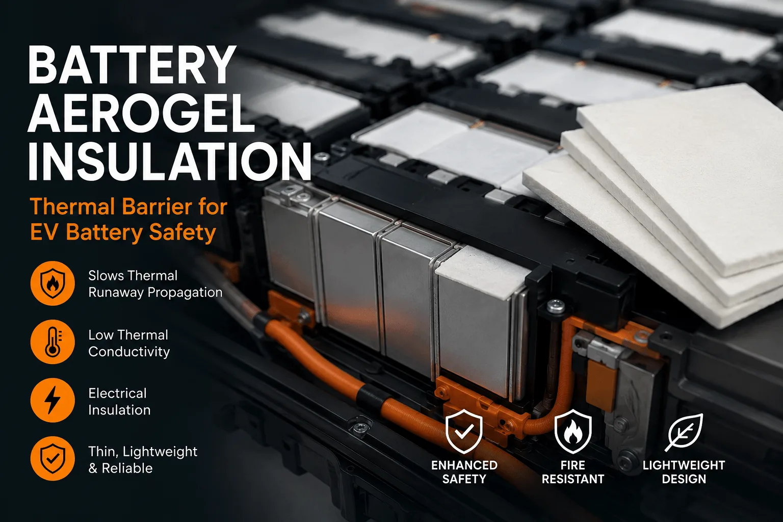
- Between prismatic cell faces. Thin die-cut pads can isolate broad cell surfaces while preserving packing density. The design must account for swelling, initial stack pressure, edge clearances, and vent locations.
- Between pouch cells or cell groups. Flexible laminates can provide thermal separation without sharp edges that could damage the pouch. Compression uniformity is critical because the cell stack changes over life.
- Around module partitions and end plates. Aerogel can slow heat reaching a structural wall, adjacent module, or pack-level component. A rigid PC or mica layer may be added when puncture resistance or higher hot-side integrity is required.
- Under pack covers and service panels. Larger barriers can protect the lid, passenger-side boundary, electronics, or service disconnect area from radiant and convective heat. Flatness, handling, fastener cutouts, and edge retention become major conversion issues.
- Near busbars and high-voltage components. Aerogel may protect against heat, but electrical insulation requirements should be assigned to a verified dielectric layer rather than assumed from the aerogel core alone.
- Around vent pathways. Shaped pads and shields can direct heat away from neighboring cells, yet they must not obstruct required pressure release. A vent-management drawing should be reviewed together with the insulation drawing.
Why Aerogel Instead of a Conventional Insulator?
The reason is not that aerogel replaces every alternative. It offers unusually high thermal resistance for a given thickness, which is valuable when the pack has little space. Other materials may be better for structure, electrical isolation, sealing, pressure control, or direct flame exposure.
Mica provides strong high-temperature and electrical performance, making it useful for covers, busbar shields, and fire barriers, but it can be more rigid or brittle in thin converted parts. Ceramic fiber can tolerate high temperatures but may require careful containment and thickness. Silicone foam is excellent for gap filling, sealing, vibration, and controlled compression, but its thermal resistance per millimeter and behavior under severe exposure must be matched to the program. Flame-retardant polycarbonate is rigid, puncture-resistant, and electrically insulating, but it is not a substitute for an inorganic high-temperature barrier.
Aerogel is most compelling when the primary problem is slowing heat through a very limited gap. The commercial answer is often a hybrid stack, not a winner-takes-all material choice.
How Polycarbonate and Silicone Foam Strengthen the Design
A flame-retardant polycarbonate sheet can provide dimensional stability, puncture resistance, a clean dielectric surface, and accurate locating features. It can protect a softer aerogel layer during handling or create a large structural insulation panel at an end plate. The PC grade, thickness, flame classification, temperature exposure, and dielectric requirements must be verified for the specific use.
Silicone foam can absorb tolerance, maintain controlled pressure, reduce vibration, and fill irregular gaps. It may help hold an aerogel barrier against the intended surface without relying on aggressive adhesive coverage. The foam’s compression-deflection curve, compression set, density, flame rating, and aging behavior determine whether it maintains the required force over vehicle life.
A practical cell-to-cell stack may therefore assign separate functions: aerogel for thermal resistance, PC film or sheet for dielectric and structural protection, and silicone foam for compliance. Separating functions can make qualification clearer and allow each layer to be optimized, but it also increases the need for laminate-level testing and change control.
| Material | Primary Function | Why It Helps | Key Risk | Typical Position |
| Aerogel | Thermal resistance | High insulation in a thin gap | Compression, edge bypass, dust | Between cells / hot boundaries |
| FR Polycarbonate | Electrical and structural | Rigid, clean and puncture resistant | Polymer temperature limits | End plates / frames / covers |
| Silicone Foam | Compliance and sealing | Controls tolerance, vibration and pressure | Compression set and aging | Gap and pressure layer |
| Mica | High-temperature shielding | Inorganic, dielectric and arc resistant | Brittleness and conversion | Lids / busbars / fire shields |
Key Specifications Buyers Should Define
- Safety objective: State whether the part must delay cell-to-cell propagation, protect a cover, shield a busbar, limit cold-side temperature, maintain electrical isolation, or support a pack-level no-propagation target.
- Cell and event conditions: Provide chemistry, format, capacity or energy, state of charge, trigger method, vent direction, maximum expected hot-side exposure, and the critical temperature of the protected component.
- Installed thickness and compression: Specify the nominal gap, tolerance stack, initial compression, cell swelling, end-of-life compression, and minimum retained thickness. Ordering by free thickness alone is not sufficient.
- Thermal performance: Request through-thickness conductivity or thermal-resistance data at relevant temperatures and pressures. Ask how films, adhesives, reinforcement, and edge seals affect the finished part.
- Hot-side integrity: Define whether the laminate must resist shrinkage, cracking, flame, hot particles, or vent-gas erosion. The surface facing the initiating cell may need a different layer from the cold side.
- Electrical performance: Define dielectric strength, insulation resistance, creepage and clearance interfaces, and post-aging requirements. Verify the complete stack rather than assuming that a silica-based core satisfies every electrical condition.
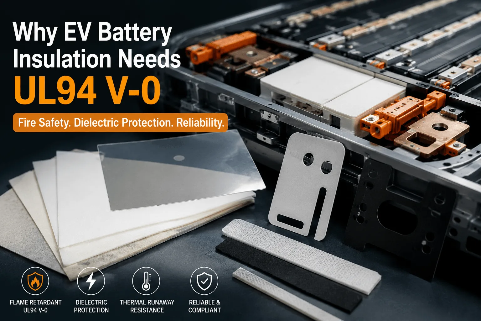
- Flame and material compliance: UL 94 V-0, VTM-0, or other material ratings may be required, but UL 94 is a controlled small-flame test and not a thermal-runaway test. Confirm the tested material, thickness, color, conditioning, and whether the rating applies to the raw layer or the finished laminate.
- Mechanical and environmental durability: Include tensile strength, edge durability, vibration, thermal cycling, humidity, chemical exposure, adhesive peel, dust limits, and storage life.
- Manufacturing controls: Define dimensional tolerance, flatness, edge-seal width, cutout quality, liner type, pull tabs, approved alternates, lot traceability, packaging, and change notification.
Why Precision Die Cutting Matters
Aerogel performance can be lost through poor conversion. An undersized part creates a direct heat path. A damaged edge releases dust or exposes the core. Excessive adhesive coverage creates a denser bridge. A narrow sealed border may delaminate after thermal cycling, while an overly wide border reduces the effective aerogel area.
DFM should review minimum web width, hole spacing, inside radii, edge-seal land, grain or reinforcement direction, adhesive pattern, release-liner split, pull-tab position, and nesting yield. For large parts, flatness and packaging may be as important as cutting tolerance. For cell-level parts, automated pick-and-place may require a stable carrier or liner that peels consistently.
Cleanliness also matters. Aerogel dust can interfere with adhesive bonding, visual inspection, or sensitive assembly areas. Reinforcement, encapsulation, dust extraction, part cleaning, protective packaging, and handling instructions should be agreed before production tooling.
A capable converter should treat the barrier as an engineered component with a controlled bill of materials, not as a commodity rectangle. That includes incoming material verification, in-process inspection, thickness checks, dimensional measurement, lot records, packaging controls, and formal approval for substitutions.
How to Validate the Barrier
Material-level validation screens the raw grades. Typical data include thermal conductivity, density, thickness, tensile behavior, dielectric properties, flame classification, and high-temperature response. This stage narrows options but cannot predict pack behavior by itself.
Converted-part validation qualifies the actual laminate. Test the selected core, films, adhesive, sealed edges, liner, cut geometry, orientation, and compression. Measure thickness distribution, peel strength, dimensional accuracy, electrical performance, dust, aging, and any hot-side exposure that can damage the construction.
Module-level testing evaluates the architecture. Use representative cells, state of charge, spacing, stack pressure, cooling, vent orientation, enclosure, sensors, and trigger method. Record temperatures, timing, voltage, gas or flame behavior, structural damage, and whether the next cell enters thermal runaway.
Pack or vehicle-level validation demonstrates compliance and occupant protection. UN R100, national standards, OEM specifications, and customer-specific tests apply to the complete system. Material certificates support the evidence chain, but they cannot replace the required abuse test.
Validation should include worst credible conditions, not only the nominal assembly. Consider minimum barrier thickness, maximum compression, aged adhesive, dimensional tolerance, high state of charge, blocked or redirected vents, coolant loss, and manufacturing variation.
Validation hierarchy: raw material data qualifies the grade, converted-part testing qualifies the laminate module and pack abuse testing qualifies the safety system.
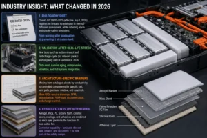
Industry Insight: What Changed in 2026
The most important change is philosophical: the industry is moving from warning after propagation begins toward preventing hazardous propagation at system level. China’s GB 38031-2025 became effective on July 1, 2026 and requires no fire and no explosion in the thermal-diffusion assessment, while also retaining alarm and smoke-safety provisions. This does not make aerogel mandatory, but it raises the value of every passive measure that can interrupt heat transfer.
A second change is validation after real-life stress. The new Chinese standard includes bottom-impact and fast-charge-cycle safety tests for relevant packs. International UNECE work in 2026 also continues to refine thermal-propagation provisions under the EV safety framework. For insulation suppliers, this means data must survive aging, compression, vibration, and system integration—not just a room-temperature coupon test.
A third change is the rise of architecture-specific barriers. The market is moving away from selecting one catalogue sheet by conductivity and toward developing a controlled component for a specific cell, vent path, pressure window, and assembly method. More RFQs now require drawings, DFM, laminate construction, test evidence, PPAP-style documentation, and change control.
A fourth change is hybridization. Aerogel, mica, PC, silicone foam, ceramic layers, coatings, and adhesives are increasingly combined so that thermal resistance, electrical isolation, structure, sealing, and assembly are assigned to the layer best suited to each function. The converter’s ability to laminate, die-cut, seal, inspect, and document the complete construction becomes part of the safety design.
Common Mistakes That Increase Risk
- Choosing the lowest conductivity number without confirming test method, temperature, pressure, or finished construction.
- Using free thickness as the specification while ignoring installed compression and end-of-life swelling.
- Treating a UL 94 rating as proof that the part will survive cell venting or stop thermal-runaway propagation.
- Adding the barrier after cell spacing, vent routing, and cooling hardware are already frozen.
- Leaving gaps around tabs, fasteners, busbars, or vents that allow hot gas and radiation to bypass the aerogel.
- Testing a raw aerogel sheet while production uses a different film, adhesive, seal width, or carrier.
- Allowing unapproved substitutions because two materials have similar room-temperature conductivity.
- Optimizing piece price while ignoring material yield, assembly labor, scrap, test failures, and redesign cost.
RFQ Checklist for a Custom Aerogel Part
- Cell format, chemistry, energy, state of charge, and module arrangement.
- 2D drawing and, where possible, the relevant 3D stack or section view.
- Nominal gap, tolerance stack, compression range, and cell-swelling allowance.
- Barrier objective, hot-side condition, cold-side limit, and required delay or no-propagation target.
- Vent position, gas direction, cooling-plate location, and metallic bypass paths.
- Required thickness, film, dielectric layer, adhesive pattern, liner, tabs, and edge seal.
- Flame, dielectric, aging, cleanliness, dimensional, and documentation requirements.
- Prototype quantity, annual volume, packaging method, validation schedule, and target SOP.
Frequently Asked Questions
Does every EV battery pack need aerogel insulation?
No. The need depends on cell chemistry, format, energy, spacing, cooling, venting, safety target, and the effectiveness of alternative barriers. Aerogel is especially attractive when high thermal resistance is required in a thin gap.
Can aerogel guarantee no thermal propagation?
No. A specific barrier can prevent or delay propagation in a validated configuration, but performance changes with cell energy, state of charge, thickness, compression, bypass paths, and abuse conditions.
Is thicker aerogel always better?
More retained thickness usually increases thermal resistance, but excessive thickness may disrupt cooling, stack pressure, pack height, cost, or cell expansion. The best thickness is the minimum that meets the tested system target with margin.
Can aerogel replace a cooling plate?
No. Aerogel resists unwanted heat transfer; the cooling plate removes routine heat. They perform different functions and may be used together.
Can aerogel provide electrical insulation?
Many aerogel composites are nonconductive, but the finished laminate must meet the project’s dielectric and insulation-resistance requirements. A separate PC, PET, PI, or mica layer may be used for controlled electrical performance.
Should the aerogel have adhesive backing?
Adhesive can simplify assembly, but it must be selected for surface energy, temperature, aging, flame behavior, peel force, and automated handling. Partial coverage may reduce thermal bridging compared with full coverage.
What is the difference between aerogel and silicone foam?
Aerogel is selected mainly for high thermal resistance per thickness. Silicone foam is selected mainly for sealing, compliance, vibration control, and pressure management. Hybrid use is common.
What should a supplier provide before sampling?
Request the material data sheet, bill of materials, thickness tolerance, test methods, flame documentation where applicable, traceability plan, drawing review, approved-alternate policy, and a proposed validation matrix.
Build the Barrier Before You Freeze the Pack
EV battery packs need aerogel insulation today because safety margins are being compressed by denser integration at the same time that system-level expectations are becoming more demanding. Aerogel offers a practical way to add thermal resistance without giving up excessive pack volume, but its value depends on how the complete component is designed, converted, installed, and tested.
The right supplier conversation starts with the failure scenario and the pack geometry—not with a request for the cheapest sheet. Share the cell format, available gap, compression range, vent location, thermal target, voltage requirement, layer preferences, drawing, prototype quantity, and annual demand. Boost Insulation can review aerogel, flame-retardant polycarbonate, silicone foam, mica, films, and adhesives as one manufacturable insulation stack, then support custom die-cut samples for your validation program.
| Need a Custom Aerogel, PC, or Silicone Foam Stack?
Send the cell format, module drawing, available gap, compression range, vent location, thermal target, dielectric requirement, prototype quantity, and annual volume. Boost Insulation can review the stack-up and prepare a manufacturable die-cut concept for validation. |
Technical Sources
- Boost Insulation. EV battery insulation, aerogel conversion, precision die-cutting, and quality-system information. Source
- Boost Insulation. Aerogel insulation and EV battery module insulation product information. Source
- United Nations Economic Commission for Europe. UN Regulation No. 100, Revision 3: rechargeable energy storage system and thermal-propagation requirements. Source
- State Administration for Market Regulation, China. GB 38031-2025, Electric Vehicles Traction Battery Safety Requirements; effective July 1, 2026. Source
- Fujian Provincial Department of Industry and Information Technology. Official industry explanation of the 2026 GB 38031-2025 thermal-diffusion, bottom-impact, and fast-charge-cycle changes. Source
- UL Solutions. Combustion tests for plastics: UL 94 V, VTM, 5V, and related test criteria. Source
- Liu Q. et al. Influence of Aerogel Felt with Different Thickness on Thermal Runaway Propagation of 18650 Lithium-ion Battery. Electrochemistry 90 (2022), 087003. DOI: 10.5796/electrochemistry.22-00048. Source
- Yang X. et al. An Experimental Study on Preventing Thermal Runaway Propagation in Lithium-Ion Battery Module Using Aerogel and Liquid Cooling Plate Together. Fire Technology 56 (2020), 2579-2602. DOI: 10.1007/s10694-020-00995-x. Source
- Tang J. et al. Suppressing Thermal Runaway Propagation of Nickel-Rich Lithium-Ion Battery Modules Using Silica Aerogel Sheets. Process Safety and Environmental Protection 179 (2023), 199-212. DOI: 10.1016/j.psep.2023.08.100. Source
- UNECE. 2026 working proposal on thermal-propagation provisions under Global Technical Regulation No. 20. Working document; not a statement of final adoption. Source
Related Posts:
How Is a Mica Insulation Sheet Used on Module End Plates?
How Does Flame Retardant Polycarbonate Prevent Fire?
What Affects the Price of Flame Retardant Polycarbonate?
What Density Is Best for Battery Aerogel Insulation?
What Is Battery Aerogel Insulation for EV Battery Packs?
Why Does EV Battery Insulation Need UL94 V-0?
 betty wong