
How Is a Mica Insulation Sheet Used on Module End Plates?
Table of Contents
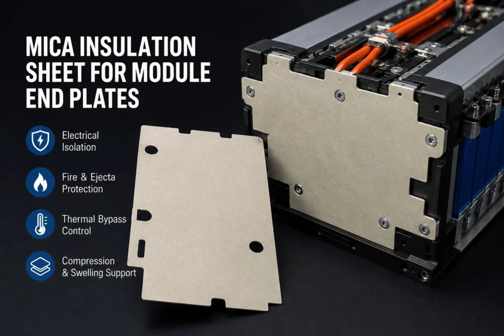
The end plate looks like a structural component, so why place a thin mica sheet on its cell-facing surface? Because the last cell in a module can transfer heat, voltage, pressure, flame, and conductive ejecta directly into a metal structure connected to side plates, fasteners, cooling hardware, and the pack enclosure. Without a proper barrier, the end plate can become both a thermal bypass and an electrical-fault path.
| A mica insulation sheet is typically installed between the end cell and the module end plate as a full-face or profiled dielectric and fire barrier. It isolates the cell case and terminals from the metal end plate, shields the structure from hot gas, flame, and conductive particles, and helps limit heat transfer along the end-plate path. The mica must be designed around vents, terminals, cooling contacts, tie rods, and compression loads. Where the module also needs swelling control or higher thermal resistance, mica is commonly combined with silicone foam, flame-retardant polycarbonate, or aerogel and validated as a complete module stack. |
Mica Insulation Sheet for Module End Plates: Quick Design Guide
| End-Plate Requirement | Mica Function | Typical Construction | Critical Check |
| Electrical isolation | Separates end cell, terminals, and busbars from metal | Mica or mica-PC laminate | Voltage, creepage, edges, humidity |
| Fire and ejecta protection | Shields plate from flame, gas, and conductive particles | Phlogopite or reinforced mica | Vent path, impingement, attachment |
| Thermal bypass control | Adds resistance between end cell and conductive structure | Mica plus aerogel where needed | End plate, bolts, rails, installed thickness |
| Compression and swelling | Maintains fire/dielectric surface in the load stack | Mica plus silicone foam | Pressure map, cycling, cracking, recovery |
How a Mica Insulation Sheet for Module End Plates Is Used
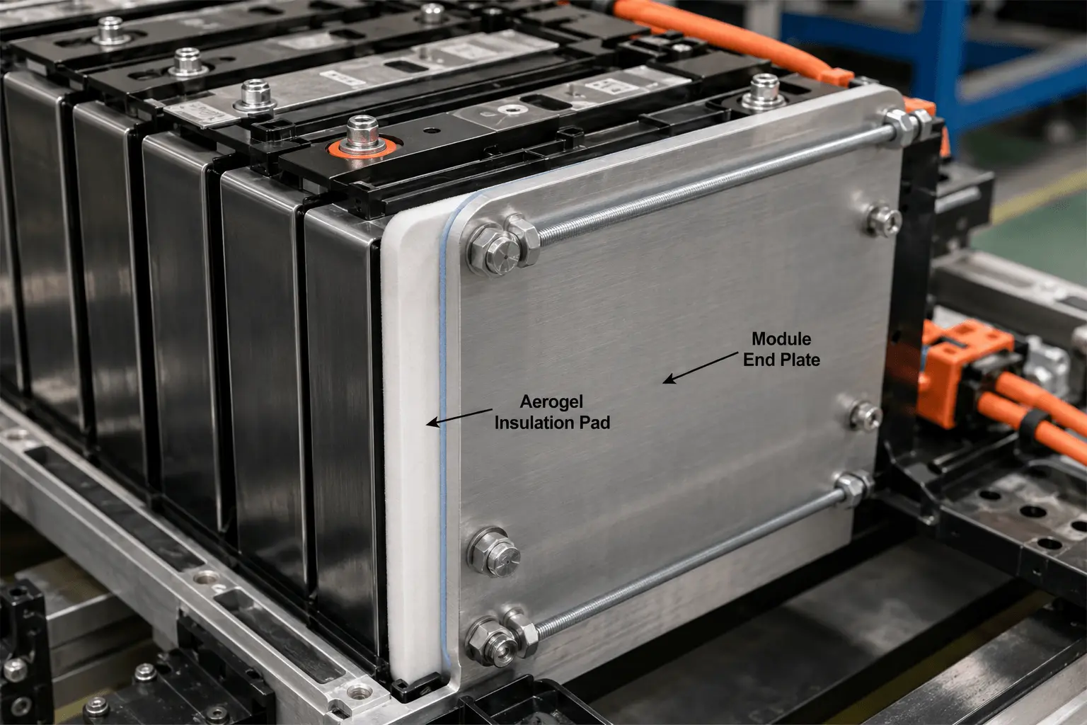
In a prismatic or pouch-cell module, the cells are normally arranged in a compressed stack. End plates close the stack at both ends and transfer clamping load through side plates, tie rods, bands, frames, or other retention structures. A die-cut mica sheet is placed on the inner, cell-facing side of one or both end plates so the last cell does not contact exposed metal directly.
The part may cover nearly the entire end-cell face, or it may be profiled around terminals, shoulders, safety vents, cooling interfaces, locating pins, fasteners, sensing components, and module rails. Some designs extend mica tabs over the upper edge or side of the end plate to protect a line-of-sight flame path. Others use a separate top shield rather than folding a rigid sheet.
The mica part can be mechanically trapped by the module preload, bonded with selective pressure-sensitive adhesive, laminated to a polycarbonate carrier, or combined with a silicone foam compression pad. The correct construction depends on whether the primary function is dielectric isolation, flame protection, thermal resistance, pressure distribution, or a combination.
Mica is not installed to carry the full structural clamp load by itself. The metal or composite end plate and retention system provide the mechanical constraint. The insulation layer must survive that load without cracking, excessive local thinning, edge extrusion, or loss of electrical coverage.
Why a Mica Insulation Sheet for Module End Plates Is Needed
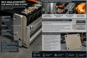
The end interface concentrates several risks. The end cell can swell against the plate, the cell can operate at a different electrical potential from the plate, and the end plate can conduct heat into side rails, fasteners, cooling structures, and the enclosure. During thermal runaway, the same interface can receive flame, hot gas, molten droplets, and conductive particles.
A mica sheet creates a high-temperature dielectric boundary between the cell and the structural plate. It can remain physically present after many polymer films soften or shrink, helping prevent the metal end plate from contacting an energized cell case, terminal region, or conductive ejecta.
Research on battery-pack thermal-runaway suppression has specifically identified the end-plate side as a heat-transfer path. In one tested design, additional thermal resistance was placed between the end cell and the module end plate to reduce conduction through that side of the module. The engineering lesson is broader than one material: the end plate should be treated as a thermal path, not only as a mechanical part.
The mica sheet also protects the end plate surface from direct flame and particles. If the end plate is aluminum, intense localized heating can spread rapidly into adjacent structural parts. Mica can distribute and delay this exposure, although severe designs may require aerogel, a thicker fire barrier, or a shaped vent shield behind or beside it.
What an EV Battery Module End Plate Actually Does
End plates maintain cell-stack geometry and help control compression. They react cell swelling, vibration, impact, and assembly preload. Their stiffness affects how evenly pressure is distributed across prismatic and pouch cells.
End plates can also support busbars, sensing harnesses, terminal covers, cooling manifolds, module mounting features, and electrical connectors. This integration makes the end region mechanically efficient, but it also places conductive and temperature-sensitive components close together.
A metal end plate is an efficient thermal conductor compared with mica, silicone foam, or aerogel. Once heated, it can transfer energy through tie rods, side plates, bolts, and pack structures. The insulation design must therefore consider both through-thickness heat transfer into the plate and in-plane heat spreading after the plate becomes hot.
The end plate does not necessarily remain electrically neutral under every fault. Conductive thermal-runaway ejecta can bridge cell cases, busbars, and structural metal. Recent research on practical high-voltage battery systems has identified case-to-case, case-to-busbar, and busbar-to-busbar arc paths. High-temperature insulating coverage around module structures is therefore increasingly important.
Where to Place the Mica Insulation Sheet on an End Plate
The default location is directly between the broad face of the end cell and the cell-facing face of the end plate. This placement interrupts direct metal contact and protects the largest facing area.
The sheet should extend to the real electrical and thermal boundary, not merely match the nominal active area of the cell. Cell shoulders, casing seams, terminal zones, welds, plastic insulators, side rails, and the edge of the end plate may become the dominant fault path.
A full-face profile is often the safest starting point for a flat prismatic cell. However, it must preserve cooling contact and safety-vent clearance. If the cell uses a top vent, the mica should normally stop below the vent or use a controlled opening. A separate mica or composite top shield can protect the end plate and busbar area without obstructing pressure relief.
For pouch cells, the sheet should avoid the pouch seal and tab roots and should provide a smooth, uniform surface. For cylindrical modules that use end frames rather than broad end plates, mica may be located as a row partition, terminal-side shield, or end-frame liner instead of a full rectangular cell-face part.
How Mica Provides Electrical Isolation at Module End Plates
A metal end plate may be grounded, connected to the enclosure, or electrically separated by the module architecture. In all cases, a mica layer can reduce the risk of a short between the end cell and the structure.
The electrical specification should define dielectric strength, insulation resistance, test voltage, dwell time, leakage-current limit, minimum production thickness, temperature, and humidity conditioning. ASTM D149 is commonly used for dielectric breakdown testing of solid electrical insulation, but the pack requirement must still be defined from the real voltage and geometry.
Creepage and clearance cannot be solved by the material certificate alone. A hole, cracked edge, metal burr, adhesive contamination, fastener, narrow web, or exposed terminal can shorten the effective path. The die-cut profile should create sufficient overlap and edge distance around high-voltage regions.
If the end plate includes bolts or inserts, the insulation may need reinforced holes, insulating washers, formed tabs, or a polycarbonate carrier. Mica provides high-temperature dielectric integrity, while the carrier can improve puncture resistance and prevent the layered sheet from cracking around hardware.
How Mica Limits the End-Plate Thermal Bypass
The end cell and end plate form a parallel heat path around intercell barriers. Even when aerogel or another separator protects the interfaces between cells, heat can travel from the last cell into the metal end plate and then through side plates, bolts, and other structures.
A mica sheet adds thermal resistance and preserves separation at high temperature. However, mica is not generally the lowest-conductivity insulation per millimeter. When delaying heat flow is the dominant objective, an aerogel layer behind the mica or a mica-aerogel laminate may provide a stronger end-interface barrier.
The completed thermal path includes the cell casing, contact resistance, mica, adhesive, foam, air gaps, end plate, fasteners, and structural rails. A low-conductivity sheet can be bypassed by one uncovered bolt or a compressed edge that contacts metal.
Instrument the center, corners, end-plate surface, side rail, tie rod, and adjacent module during thermal testing. The hottest path is often not located at the geometric center of the mica part.
How Mica Protects End Plates During Thermal Runaway
During thermal runaway, the end cell may eject flame and particles upward, sideways, or through a casing rupture. Mica can shield the end plate and nearby high-voltage hardware from direct exposure.
The material’s value is its ability to retain a physical and dielectric layer at temperatures that can degrade ordinary polymer films. It can reduce direct flame contact, slow hot-particle erosion, and keep conductive debris away from the metal plate.
The sheet should not be described as a universal propagation stopper. Hot gas can flow around its edge, flame can pass through an oversized terminal opening, and heat can travel through bolts or the cooling plate. The end-plate barrier is one part of vent routing, cell spacing, cooling, detection, and enclosure protection.
For a severe vent-facing interface, use application-relevant burner, hot-gas, particle, or cell-vent testing. Small-scale flammability classifications do not reproduce pressure, ejecta, heat flux, or the three-dimensional flow around an end plate.
How the Mica Sheet Interacts With Module Compression
Prismatic and pouch modules use compression to maintain cell contact, control swelling, and stabilize the stack. The end-plate insulation sits directly in this load path, so its stress-strain response affects the assembly.
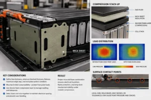
Rigid mica has limited compressibility. It can distribute load over a flat surface, but local end-plate ribs, weld beads, bolt bosses, adhesive overlaps, or cell tolerance can create point pressure and crack the sheet. A cracked part may still look installed while losing dielectric and flame coverage.
The drawing should define free thickness, minimum finished thickness, flatness, maximum edge step, and the end-plate surface condition. Pressure mapping and prototype stack measurements can identify nonuniform load.
Where significant swelling or tolerance must be absorbed, add a controlled silicone foam compression layer rather than expecting mica to act as a spring. The foam and mica should be selected together so the foam does not overbend the mica or reduce the required electrical spacing.
Mica Insulation Sheet for Module End Plates on Prismatic Cells
Prismatic modules are the most direct application because the last cell presents a broad, relatively flat surface to the end plate. A near-full-face die-cut mica sheet can provide consistent dielectric and flame coverage.
The profile should account for cell-case seams, top shoulders, terminal and busbar regions, vent keep-outs, base cooling contact, and module rails. The mica should not create a step that concentrates clamp pressure on the cell casing.
If the end cell vents upward, a separate top-edge mica part or mica-PC cover can protect the end plate, terminal area, and harness. Extending a rigid broad-face sheet over a sharp corner without a qualified bend radius can create cracks.
End-of-life swelling should be included in the compression calculation. The mica must retain coverage and not be crushed below the minimum validated thickness when the cell stack expands.
Mica Insulation Sheet for Module End Plates on Pouch Cells
Pouch cells are more sensitive to local pressure and surface defects. The end-interface construction should be smooth, compliant, and free from sharp cut edges, adhesive ridges, liner fragments, and exposed reinforcement.
A thin flexible mica laminate can provide high-temperature dielectric protection, while silicone foam controls stack pressure. In some designs, a smooth polymer film or thin polycarbonate layer is placed toward the pouch to prevent abrasion, with mica positioned toward the end plate or predicted hot side.
The mica profile should avoid pouch seals, tabs, and gas pockets. The active electrode area does not define the complete mechanical envelope, so the cell manufacturer’s dimensional and swelling data are required.
Test aged and swollen stacks. A design that distributes pressure evenly on new flat pouches may develop high local stress after hundreds of cycles and thermal expansion.
How Module End-Plate Mica Applies to Cylindrical Cells
Cylindrical modules may not use broad cell-face end plates in the same manner as prismatic stacks, but they still have terminal-side frames, row ends, compression structures, and module boundaries.
Mica can be used as an end-frame liner, row-end barrier, terminal shield, busbar insulator, or under-cover fire layer. The part often requires more complex cutouts because cell holders, vents, cooling channels, and busbars occupy the end region.
Open channels between cylinders can carry hot gas around a flat barrier. End-frame mica must therefore be coordinated with top shields, vent manifolds, and row partitions.
A mechanically reinforced mica laminate is often more suitable than unsupported thin mica paper because the part must retain its shape around holders and airflow paths.
Choosing Muscovite or Phlogopite for Module End Plates
Muscovite is commonly associated with strong dielectric performance and dimensional stability. It can be suitable for end-plate barriers where normal-service electrical insulation, precision cutting, and moderate high-temperature exposure dominate.
Phlogopite generally provides greater temperature capability and is often selected where the end cell or end plate can face direct flame or severe hot-gas exposure.
The mica species is not the only selection factor. Binder chemistry, reinforcement, thickness, density, flexibility, adhesive, and surface film can determine the final result. A high-temperature mineral with an unsuitable acrylic adhesive can fail earlier than a well-designed lower-temperature laminate.
Specify the exact approved grade and source. A substitution between muscovite and phlogopite or between suppliers should trigger engineering review and, where relevant, repeat electrical and abuse testing.
How Thick Should End-Plate Mica Insulation Be?
There is no universal end-plate thickness. Thin mica can provide local dielectric isolation; thicker sheet can improve burn-through time, stiffness, puncture resistance, and thermal resistance.
The correct thickness depends on pack voltage, end-plate geometry, cell energy, vent direction, available gap, unsupported span, fastener layout, compression pressure, and the required thermal-runaway result.
Specify minimum finished thickness rather than only a nominal value. Grinding, pressing, adhesive lamination, die cutting, local clamping, and tolerance can create thinner areas.
Prototype at least two thickness or laminate options when the design is new. Compare electrical margin, pressure distribution, cracking, cold-side temperature, mass, assembly time, and total converted-part cost.
Binder, Reinforcement, and Edge Construction
Commercial mica sheets contain a binder that holds mica paper or flakes together. Silicone binders are commonly selected for high-temperature flexibility, while epoxy systems can create stiffer boards.
Glass fabric or other reinforcement improves tensile strength, puncture resistance, and post-fire support. It can also increase stiffness, heat conduction, thickness, and edge-fray risk.
At an end plate, edge integrity is critical. A cracked terminal window or delaminated hole can expose metal and reduce creepage. Define allowable chipping, delamination width, loose particles, burrs, and exposed adhesive.
If the part uses sealed or film-covered edges, confirm that the seam does not become a thick pressure ridge. A wide polymer seam can reduce the active mica area and create a different thermal path.
Should the Mica Be Adhesive-Backed?
Adhesive backing can hold the mica on the end plate during subassembly, transportation, and cell-stack loading. It can also prevent the sheet from sliding before final compression.
Full-face adhesive is not always necessary. It adds a continuous polymer layer, increases contact, and can change heat transfer, flame behavior, mass, and cost. Selective perimeter or registration zones may provide sufficient fixation.
Adhesive should be kept away from vents, terminals, welds, cooling interfaces, and direct-flame edges unless the exact construction has been validated. Squeeze-out can contaminate electrical surfaces or create an unwanted bridge.
Test peel, shear, creep, humidity aging, thermal cycling, and liner release on the actual end-plate surface. Painted aluminum, bare aluminum, steel, e-coated metal, and polymer end plates have different bonding behavior.
Mica and Flame-Retardant Polycarbonate on End Plates
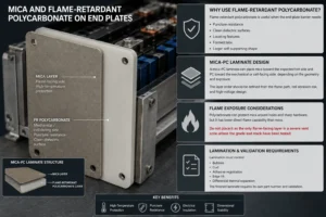
Flame-retardant polycarbonate is useful when the end-plate barrier needs puncture resistance, clean dielectric surfaces, locating features, formed tabs, or a larger self-supporting shape.
A mica-PC laminate can place mica toward the expected hot side and PC toward the mechanical or cell-facing side, depending on the geometry and exposure. The layer order should be defined from the flame path, cell abrasion risk, and high-voltage design.
Polycarbonate can protect mica around holes and sharp hardware, but it has lower direct-flame capability than mica. Do not place it as the only flame-facing layer in a severe vent zone unless the grade and stack have been tested.
Lamination must control bubbles, curl, adhesive registration, edge lift, and differential thermal expansion. The finished laminate requires its own part number and validation.
Mica and Silicone Foam on Module End Plates
Silicone foam is used to manage cell swelling, tolerance, vibration, and preload. Combining it with mica can create a multifunctional end-interface pad.
The mica layer provides the high-temperature dielectric and flame surface. The foam distributes pressure and absorbs end-of-life expansion. Industry composite solutions use this principle for thermal-propagation mitigation and cell-swelling management.
The compression curve should match the module’s load target. Foam that is too stiff can overload the last cell; foam that is too soft can allow stack movement or reduce clamp retention. The mica should not be forced into a sharp end-plate rib.
Test the stack after compression cycling and heat aging. Measure thickness recovery, pressure distribution, mica cracking, adhesive condition, and thermal performance.
Mica and Aerogel at the End-Plate Interface
Aerogel is valuable when the design needs greater thermal resistance between the end cell and the metal plate. Mica protects against flame, particles, and electrical contact, while aerogel slows heat transfer.
A practical stack can use mica on the hot or metal-facing side and aerogel as the insulating core. The layer order depends on vent direction, surface smoothness, compression, and the required dielectric surface.
Aerogel is compression-sensitive and may release particles if not encapsulated. Mica is comparatively rigid. The laminate should avoid hard edge steps and should maintain the validated installed aerogel thickness.
Test the complete stack under module preload. A strong room-temperature coupon result can disappear if the aerogel is crushed, the mica edge bridges the gap, or full-face adhesive creates a parallel heat path.
Vent, Terminal, and Cooling Keep-Out Design
The end-plate mica drawing should begin with three keep-out maps: safety venting, high-voltage terminals and busbars, and normal cooling interfaces.
The vent must open and discharge into a controlled route. The mica can shield the end plate and receiving surfaces but should not trap pressure. Use shaped openings, stand-off spacing, top shields, or deflectors where required.
Terminal openings should maintain dielectric overlap and prevent a straight conductive path from the terminal or busbar to the end plate. Reinforced edges or a PC carrier can improve durability around these cutouts.
Cooling contact should remain unobstructed where the cell is designed to transfer normal heat into a base or side cooling plate. Mica is a barrier, not a thermal interface material. Blocking the intended cooling path can increase routine cell temperature.
DFM for a Mica Insulation Sheet for Module End Plates
End-plate parts are often large, thin, and geometrically complex. They may include terminal windows, tie-rod holes, locating slots, asymmetric features, vent clearances, foam islands, and adhesive zones.
Sharp internal corners and narrow webs increase crack risk. Use practical radii, adequate hole-to-edge distance, reinforced critical zones, and sufficient material between adjacent cutouts.
Flatbed die cutting, rotary die cutting, CNC processing, and other methods may be considered according to thickness, rigidity, volume, and feature size. Tool sharpness, die clearance, support liner, cutting pressure, and dust extraction must be controlled.
The drawing should specify overall dimensions, critical datums, thickness, flatness, edge quality, delamination limits, adhesive registration, liner split, pull tabs, orientation, cleanliness, labeling, and packaging.
Prototype the actual laminate. A bare mica sheet may cut cleanly while the same geometry cracks after foam, PC, adhesive, or glass reinforcement is added.
How to Validate End-Plate Mica Insulation
Level 1 validates the material and laminate: thickness, areal mass, dielectric strength, insulation resistance, high-temperature shrinkage, flame response, tensile or flexural strength, moisture, and chemical compatibility.
Level 2 validates the die-cut component: dimensions, edge cracks, delamination, holes, flatness, puncture, adhesive peel, liner release, particle contamination, and packaging.
Level 3 validates the compressed end interface. Build the end cell, mica or composite pad, end plate, tie rods, and side structure. Measure pressure distribution, installed thickness, creep, swelling response, and electrical isolation.
Level 4 applies representative heat flux, flame, hot gas, particles, or a cell-level thermal-runaway trigger. Instrument the end cell, mica surfaces, end plate, bolts, side rails, busbars, cooling structures, and adjacent module.
Level 5 validates the complete module and pack. Confirm thermal propagation, warning, controlled venting, enclosure response, electrical isolation, and post-event condition. UN Regulation No. 100 addresses the complete rechargeable energy storage system or vehicle; a mica sheet certificate cannot establish compliance.
Common End-Plate Mica Design Mistakes
The first mistake is covering only the center of the end cell while leaving the shoulder, edge, bolt, or busbar path exposed.
The second mistake is expecting rigid mica to manage cell swelling. Use a defined compression layer or spring system when significant movement is expected.
The third mistake is blocking the cell vent or creating a pocket that redirects hot gas toward the end plate, harness, or neighboring cell.
The fourth mistake is using room-temperature dielectric data without checking edge cracks, moisture, thermal aging, and post-fire electrical separation.
The fifth mistake is assuming the end plate is not part of the thermal path. Metal side structures and fasteners can bypass excellent intercell insulation.
The sixth mistake is changing the mica grade, binder, reinforcement, adhesive, thickness, or converter after validation without formal engineering review.
Industry Insight: End Plates Are Becoming Multifunctional Safety Interfaces
Higher pack integration is changing the role of the end plate. It is no longer only a mechanical compression component; it can also support vent routing, busbars, sensors, cooling manifolds, electrical isolation, and module-to-pack mounting.
This integration increases the value of multifunctional insulation. Mica-PC laminates can combine high-temperature and structural dielectric functions. Mica-foam pads can combine fire protection and compression. Mica-aerogel stacks can control the end-plate heat bypass.
Current battery-safety research is also highlighting conductive ejecta and high-voltage arc paths in tightly integrated packs. Protecting the end cell, busbar, and metal end structure with high-temperature insulation is therefore becoming more important, particularly in 800 V and cell-to-pack architectures.
For sourcing teams, the differentiator is moving from raw-sheet price to converted-part capability: early DFM, rapid laminate prototypes, controlled edges, pressure-compatible stacks, automotive documentation, and repeatable high-volume production.
How to Specify a Mica Insulation Sheet for Module End Plates
Identify the cell format, chemistry, capacity, state of charge, end-cell dimensions, vent location, terminal and busbar geometry, cooling interface, end-plate material, surface finish, retention system, and compression range.
Specify mica type, binder, reinforcement, rigid or flexible construction, nominal and minimum thickness, dielectric strength, insulation resistance, temperature and flame exposure, moisture conditioning, and approved supplier.
The drawing should define protected coverage, vent and cooling keep-outs, terminal windows, edge overlap, holes, minimum webs, radii, adhesive zones, foam zones, liner split, pull tabs, flatness, edge quality, orientation, and packaging.
Add pressure and swelling requirements, validation tests, sampling, PPAP level, lot traceability, and change-control conditions. The specification must cover the complete production laminate rather than only the mica core.
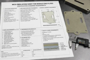
RFQ Checklist for Module End-Plate Mica Parts
Provide the cell and module drawing, end-plate CAD, pack voltage, module electrical configuration, vent direction, cooling method, installed gap, compression range, swelling allowance, and expected thermal-runaway exposure.
State the required electrical test voltage, insulation resistance, temperature or flame test, cold-side temperature target, burn-through criterion, pressure-distribution target, and module-level acceptance criterion.
Define the desired stack: mica alone, mica plus PC, mica plus silicone foam, mica plus aerogel, adhesive-backed construction, or an open material-selection request.
Include prototype quantity, annual volume, tooling expectations, packaging, traceability, PPAP level, production timing, and any current cracking, short-circuit, thermal-bypass, compression, or assembly problem.
How Boost Insulation Supports Module End-Plate Insulation
Boost Insulation’s current public website describes a China-based EV battery insulation and precision die-cut manufacturer certified to IATF 16949 and ISO 9001. The site promotes DFM support, in-house tooling, controlled-environment lamination and die cutting, rapid prototyping, APQP and PPAP support, and lot traceability.
Its public capabilities include mica, flame-retardant polycarbonate, aerogel, silicone sheets and foams, thermal materials, films, adhesives, CNC processing, slitting, lamination, and rotary die cutting. The site also states suitable custom components can be held to tight dimensional tolerances and prototype samples can be supplied within 48 hours.
For an end-plate project, engineering support can include thermal and electrical coverage review, mica grade selection, mica-PC or mica-foam lamination, aerogel integration, compression-stack analysis, adhesive zoning, edge reinforcement, die-cut DFM, prototype tooling, dimensional inspection, voltage testing, and validation-sample preparation.
A useful inquiry should include the end-cell and end-plate CAD, vent path, voltage, installed gap, pressure range, material restrictions, thermal-runaway test target, annual volume, and PPAP requirements.
| Need a custom module end-plate insulation stack?
Send Boost Insulation the end-cell and end-plate CAD together with the vent path, voltage, installed gap, compression range, swelling allowance, dielectric target, flame or thermal-runaway test, annual volume, and PPAP requirements. The engineering team can review mica, flame-retardant PC, silicone foam, aerogel, adhesives, and precision die-cut options. Visit boostinsulation.com to upload a drawing or request a quote |
Frequently Asked Questions
Why is mica placed between the end cell and the end plate?
It electrically isolates the end cell from metal, shields the end plate from flame and conductive particles, and adds resistance to the end-plate heat-transfer path.
Should mica cover the entire end cell?
Near-full coverage is a strong starting point for prismatic cells, but the part must preserve vents, terminals, busbars, cooling contacts, and required clearances. The final profile follows the real risk map.
Can mica control cell swelling at the end plate?
Mica has limited compressibility and should not be treated as the main swelling-management layer. Combine it with silicone foam, springs, or another controlled compression system when movement is significant.
Is mica or aerogel better at the module end plate?
Mica is stronger for flame, particles, dielectric protection, and high-temperature integrity. Aerogel generally provides greater thermal resistance. A combined stack is often effective when both functions are required.
Can mica be laminated to polycarbonate?
Yes. Polycarbonate can improve puncture resistance, clean surfaces, locating features, and edge durability. The layer order and finished laminate must be validated for flame and electrical exposure.
Should end-plate mica use full-face adhesive?
Not automatically. Selective adhesive may hold the part while reducing polymer content and thermal bridging. Adhesion must be tested on the actual end-plate coating and environment.
How thick should end-plate mica be?
There is no universal thickness. Select the minimum production thickness that meets dielectric, flame, mechanical, compression, and module-test targets with manufacturing margin.
What drawings are needed for a custom end-plate part?
Provide the end cell, end plate, busbar, vent, cooling, tie-rod, compression, and module assembly drawings, plus voltage, test criteria, volume, and PPAP requirements.
Technical References
- Boost Insulation. EV battery insulation, precision die cutting, DFM, 48-hour rapid prototyping, APQP, PPAP, and lot-traceability capabilities. Source
- Ye, Z. and Fu, X. Experimental and Simulation Investigation on Suppressing Thermal Runaway in Battery Pack. Scientific Reports, 2024. The study identifies the module end-plate side as a heat-transfer path and adds thermal resistance at that interface. Source
- Yu, Z. et al. Thermal Runaway-Induced Short-Circuit Arc in Highly Integrated Lithium-Ion Battery Systems: Mechanisms, Thresholds, and Mitigation Strategies. Communications Engineering, 2026. Source
- Michelini, E. et al. Experimental Investigation on Reversible Swelling and the Mechanical Behavior of Lithium-Ion Pouch Cells. Batteries, 2023. Source
- Logakannan, K. P. et al. Testing and Modeling of Vehicle Li-Ion Battery Modules with Prismatic Cells. Energies, 2023. Source
- Saint-Gobain Tape Solutions. EV Battery Composites: mica/foam barriers for thermal-propagation mitigation and cell-swelling management. Source
- ASTM International. ASTM D149-25, Standard Test Method for Dielectric Breakdown Voltage and Dielectric Strength of Solid Electrical Insulating Materials. Source
- IEC. IEC 60371-1 and IEC 60371-2, specifications and test methods for insulating materials based on mica. Source
- UNECE. UN Regulation No. 100, Revision 3, rechargeable electrical energy storage system requirements. Source
- UNECE. Proposal for the 05 Series of Amendments to UN Regulation No. 100, including improved thermal-propagation procedures. Source
Related Posts:
How Do You Choose a Flame Retardant PC Supplier?
What Makes Aerogel Effective Between Battery Cells?
How Does Aerogel Handle Cell Venting Heat in EV Packs?
How Is Aerogel Used Near EV Battery Module End Plates?
What Density Is Best for Battery Aerogel Insulation?
How Do You Choose Battery Aerogel Insulation for EVs?
 betty wong
