
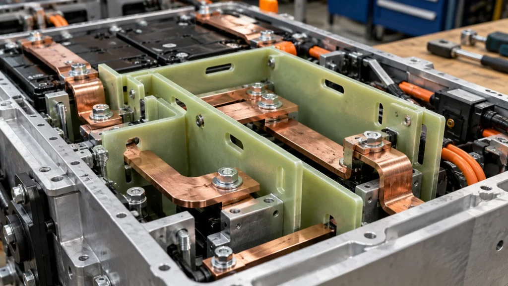
How Do You Design CNC-Machined FR4 Busbar Barriers?
Table of Contents
An FR4 busbar barrier can look like a straightforward plate until it reaches the assembly station. A mounting hole may shift the barrier toward an exposed terminal, a slot may leave a fragile bridge, and a nominally accurate outer profile may locate incorrectly against the actual busbar hardware. Even a sound starting laminate cannot correct a misplaced datum or damaged machined edge. For reliable EV battery insulation, design has to begin with the installed busbar assembly, not an isolated two-dimensional outline.
Engineers design CNC-machined FR4 busbar barriers by mapping the busbar layout, electrical isolation boundaries, nearby metal, mounting interfaces, and available assembly space. They then specify a suitable laminate grade and candidate thickness; design the outer profile, coverage, holes, slots, and cutouts; and select functional datums and tolerances. A CNC-focused design-for-manufacturing (DFM) review must address tool access, internal corners, narrow sections, workholding, drilling, edge quality, and cleaning. Finished parts require dimensional inspection and prototype fit checks, followed by application-specific electrical, mechanical, and environmental validation of the installed assembly.
Key Engineering Takeaways
- Translate the real busbar assembly and its electrical boundaries into measured barrier geometry.
- Design coverage, holes, slots, fasteners, and datums as functional interfaces, not decorative cuts.
- Allocate critical tolerances by installed fit; review cutter access, edge condition and cleanliness.
- Inspect the CNC part, then validate it in the representative electrical assembly.
What Is a CNC-Machined FR4 Busbar Barrier?
A CNC-machined FR4 busbar barrier is a rigid, custom-profiled glass-epoxy insulation component positioned around energized copper or aluminum conductors. Depending on the architecture, it may be a divider between busbars, a terminal-separation plate, a busbar-to-frame shield, or a local insert protecting a defined interface. Its mechanical role may range from holding its own position to supporting selected hardware, provided the actual load case is evaluated.
FR4 is a family of flame-retardant glass-reinforced epoxy laminates, not a single universal performance specification. Procurement must identify the required grade and supplier-supported properties; G10 should not automatically be treated as equivalent to FR4. A material datasheet describes tested laminate specimens. It does not certify the dielectric performance, flatness, edge condition, or assembled clearances of a routed battery component. For general FR4 applications, see Boost Insulation’s existing article on rigid FR4 battery insulation: https://boostinsulation.com/fr4-rigid-insulation-for-ev-battery-packs/.
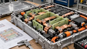
Start With the Busbar Assembly, Not a Blank FR4 Outline
Obtain an assembly layout showing busbar surfaces, terminals, enclosure, brackets, sensors, covers, fasteners and installation direction. Identify energized, grounded, floating and same-potential metal. Include dimensional variation and expected movement relevant to the isolation interfaces.
The design authority must specify the electrical architecture, working and transient conditions, creepage and clearance targets and validation requirements. IEC 60664-1:2020+A1:2025 supplies an insulation-coordination framework within its stated scope; EV-specific applicability must be reviewed. The task here is to turn approved requirements into measurable part geometry, not derive generic FR4 spacing values.
Table 1. Design inputs that should exist before the FR4 drawing is released
| Design input | Functional requirement | Drawing / DFM implication |
| Busbar / terminal layout | Identify conductive and mating features | Define coverage / openings |
| Potential map | Mark interfaces needing isolation | Control critical edges |
| Creepage / clearance | Preserve approved insulation paths | Control surfaces / air gaps |
| Enclosure geometry | Avoid interference | Define envelope / datums |
| Assembly sequence | Preserve installation access | Design cutouts / direction |
| Grade / thickness | Match required laminate duty | State material / tolerance |
| Hardware / loads | Accommodate mounting and movement | Place holes / remaining material |
| Environment | Address contamination and exposure | Define cleaning / validation |
Define the Barrier’s Function and Isolation Boundary
A rigid FR4 divider differs from a PC busbar protective cover (https://boostinsulation.com/why-use-pc-insulation-around-ev-battery-busbars/), and from a barrier facing grounded metal. A retained plate also differs from a bolted support. Specify the primary duty, then mark the locations where FR4 must prevent contact or preserve prescribed insulation paths.
Bulk dielectric separation, surface creepage and air clearance remain distinct. More FR4 thickness does not correct every surface route or protruding fastener. If the busbar architecture cannot provide the approved separation, revise the assembly. Electrical design ownership should be clear before the machining drawing is finalized.
Table 2. Barrier geometry and its electrical function
| Geometry feature | Electrical purpose | Risk | Verification |
| Edge overlap | Maintain intended barrier coverage | Exposed conductor at stack-up extreme | Installed coverage |
| Busbar window | Allow a required connection | Reduced separation | Clearance review |
| Fastener opening | Mount without interference | Metal approaches HV surface | Hardware envelope |
| Datum | Position the barrier | Shifted coverage | Datum-to-busbar fit |
| Slot / relief | Provide functional access | Altered path / weak section | DFM and insulation review |
| Perimeter | Fit the pack envelope | Interference or short overlap | Profile / assembly check |
How Do You Determine Barrier Coverage and Edge Extension?
Project the relevant busbar and terminal features onto the actual plane of the barrier, including bolt heads, conductor bends, tabs, and connection transitions. Determine where an FR4 overlap genuinely separates the intended conductors and where an opening is required for electrical connection or service. A plate may need localized projections near terminals rather than a uniformly oversized rectangle.
Next, add the effects of assembly placement, fastener play, busbar position variation, and plausible movement. The required edge extension follows the specified isolation boundary and dimensional stack-up; there is no universal number of millimeters that makes every barrier safe. An excessive extension can also obstruct ventilation, maintenance, vent paths, or fastener access. Review the coverage in the complete model and verify it on a physical prototype.
How Do You Design the Outer FR4 Profile?
Create the perimeter around the functional envelope. Maintain enough material to connect mounting tabs, isolating regions, and any unsupported projections. Avoid decorative notches or long fragile fingers unless they solve a defined packaging or assembly requirement. Identify regions where a CNC fixture must support the part and where a cutter must reach without damaging adjacent features.
The routing strategy can influence how small tabs, acute contours, and free edges behave during production and handling. Simplifying a perimeter may reduce setup changes and inspection burden, but it must not remove insulation coverage. Coordinate design revisions with electrical engineering so a seemingly harmless contour optimization does not alter the position of a critical edge near a conductor.
How Should Mounting and Locating Holes Be Designed?
Every hole needs a defined job: clearance for a bolt, accurate location on a pin, passage for a connector, or access for an assembly tool. Clearance holes and locating holes should not receive the same geometric controls by default. For a located barrier, identify the feature or feature pair that establishes position, and allow other holes the intended assembly freedom without overconstraining the laminate.
Review the complete installed fastener, not just the nominal shank: head, washer, insert, insulating sleeve, stand-off, bolt-tip protrusion, and tool access. A hole can reduce remaining material, concentrate stress, expose a new surface, or position conductive hardware closer to an energized busbar. The electrical impact depends on actual potentials and contact points. An isolated bolt is not automatically a short circuit, and a metal fastener passing through FR4 is not automatically electrically isolated.
For drawings, separate hole diameter, hole position, and edge-location tolerances. Control the ones relevant to alignment and electrical separation. Do not select a minimum diameter or hole-to-edge distance from a generic rule without checking the laminate grade, cutter, fixture, and load case.
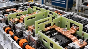
How Do Slots and Cutouts Change the Design?
A slot may locate the barrier, clear a terminal, permit adjustment, or affect a prescribed surface path. Those purposes are different. Check its actual ends, nearby metal, width and contamination conditions under the applicable insulation-coordination method; an arbitrary slot cannot be assumed to increase creepage.
Cutouts remove material and may leave fragile bridges. A large opening can increase deflection without changing nominal sheet thickness. Evaluate remaining ligaments, corners, part handling and workholding. Sometimes revising the opening or adding support is better than compensating with a thicker plate.
Table 3. Hole, slot and cutout review
| Feature | Electrical issue | Mechanical issue | CNC / DFM review |
| Clearance hole | Hardware potential / spacing | Bearing interface | Size, position, breakout |
| Locating hole | Barrier registration | Overconstraint | Datum, drill quality |
| Long slot | Surface path and terminals | Reduced web | Ends, cutter, fixture |
| Busbar window | Live edge / connector gap | Reduced section | Corner, toolpath |
| Large cutout | Exposed metal | Stiffness, handling | Fixture, remaining material |
| Narrow bridge | Damage near HV features | Fragile section | Cut, inspect, protect |
Why Do Internal Corner Radii and Narrow Sections Matter?
A conventional rotating CNC end mill cannot directly form a mathematically sharp internal corner. If mating hardware demands such a corner, either revise the mating geometry or evaluate another approved process and its cost, inspection, and edge consequences. The cutter diameter and the workholding plan determine what is practical, so do not assign an unverified universal internal radius in a public guide.
Internal corners are also locations where mechanical stress may concentrate. Very narrow bridges can be vulnerable during routing, depaneling, packaging, and assembly. Protect them from unsupported cutting forces and clarify acceptance criteria for chipping or local delamination. The engineering drawing should show the required geometry without implying that zero-radius corners or extremely small webs are automatically achievable.
How Do Fastener Interfaces Affect the Barrier Drawing?
Show the complete hardware stack in the assembly model. A washer that distributes clamping load may extend beyond a nominal hole and change the shortest air gap to an energized busbar. A metal sleeve or stand-off may connect parts at the same potential, or it may inadvertently bridge an intended isolation boundary. Insulating bushings and shoulder washers can help in a properly engineered joint, but their material, position, compression behavior, and electrical rating must also be evaluated.
Define mounting-hole envelopes, relevant cross-sections, and any required isolation accessories so manufacturing and assembly teams do not infer details from a single diameter callout. The dedicated question of direct conductive bypass deserves its own system-level analysis; this article addresses how to represent and control those interfaces in a manufacturable FR4 part.
Select Functional Datums Before Assigning Tolerances
A useful datum reflects real installation. If the barrier seats on a bracket and is located by a pin, those interfaces should govern the coordinate scheme—not a distant cosmetic edge. A two-hole locating scheme needs a clear definition of each hole’s role, allowance for mating-part variation, and avoidance of unintended overconstraint.
Trace electrically important edge locations through the mounting geometry to the actual conductor. Otherwise a nominally conforming FR4 part may still shift toward a terminal. Review stack-up from busbar support, enclosure and hardware together; the part drawing alone cannot guarantee installed separation.
Table 4. Datum and tolerance allocation
| Dimension / datum | Functional importance | Control strategy | Inspection |
| Locating interface | Installed orientation | Match assembly scheme | Simulated datum |
| Hole pattern | Bracket fit | Position from datums | Pattern check |
| HV-adjacent edge | Coverage / isolation | Critical relative location | Datum-to-edge |
| Busbar window | Connection / clearance | Size plus position | Window measurement |
| Sheet thickness | Stack and solid barrier | Grade / tolerance | Material check |
| Cosmetic perimeter | Handling / appearance | General tolerance | Profile sampling |
Which Dimensions Need Tight Control—and Which Do Not?
Electrical-critical features include barrier extensions near exposed conductors, fastener-to-conductor distances, terminal windows, and slot boundaries that form part of an approved insulation design. Assembly-critical features include locating holes, mating faces, mounting patterns, and thickness where it affects stack height. General perimeter segments with generous surrounding space usually do not merit the same controls.
Also distinguish material thickness tolerance from CNC profile and hole-position tolerance. They arise from different sources and may require different incoming checks. Where flatness matters, specify how it is measured and in what condition: free-state, restrained, or installed. Blanket tight tolerances raise inspection and manufacturing difficulty without necessarily improving the function. A risk-based scheme is more useful than a drawing where every dimension appears equally critical.
How Does Thickness Affect a CNC-Machined FR4 Barrier?
Select a candidate grade and thickness from the approved electrical, packaging, and mechanical requirements. Plate thickness influences solid dielectric path and board stiffness, but cannot substitute for creepage, clearance, or sound placement of conductive hardware. It also affects drilling engagement, routing strategy, unsupported-span deflection, weight, and fastener-stack design.
When a barrier is required to carry loads, evaluate its actual support conditions and allowable movement; do not equate a laminate’s nominal stiffness with primary structural suitability. Where severe thermal exposure dominates, compare mica and FR4 (https://boostinsulation.com/mica-insulation-sheet-vs-fr4-boards/) rather than simply increasing FR4 thickness. Treat thickness as one controlled design input and use the separate FR4 thickness-selection framework for a complete selection exercise.
How Do CNC Routing and Drilling Affect Finished FR4 Quality?
FR4’s glass reinforcement is abrasive to cutting tools, and its layered construction requires attention to support, tool condition, and cutting forces. Routing an exterior profile and machining small internal openings may require different strategies. Tool wear can affect edge finish and dimensional repeatability; poor workholding can permit local vibration or lifting. Exact feeds, speeds, cutter grades, and holding methods must be established by the fabricator for the selected laminate and geometry, not copied from a generic online chart.
Drilling deserves separate review. Hole location, entry and exit support, tool wear, and the condition of the laminate around the hole can affect both assembly fit and inspection results. Edge chips, exposed fibers, or local delamination should be evaluated against the actual part function and agreed acceptance criteria. An imperfection is not automatically a dielectric breakdown, but damage near a critical insulation boundary cannot be dismissed as cosmetic either.
Why Do Edge Condition and Cleaning Belong in the Drawing?
CNC machining changes the condition of the edge and hole wall compared with an uncut sheet. Drawings should identify critical surfaces, unacceptable defects, inspection expectations, and any deburring or handling requirements supported by the chosen process. Avoid broad statements such as “all edges must be perfect”; define what matters for fit, remaining section, contamination control, and the electrical boundary.
Cleaning is equally important. Glass/epoxy debris is not universally conductive, but metal chips from mixed operations, ionic residues, coolants, moisture, and dust accumulation can alter high-voltage surface conditions. Agree on post-machining cleaning, inspection, and packaging appropriate to the customer’s assembly. A clean part at shipment can still be contaminated later by the customer’s assembly process, so cleanliness controls must continue through installation.
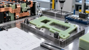
CNC / DFM Review: What Should the Supplier Challenge?
The best DFM review is not merely a promise that the file can be machined. It checks whether the required geometry can be produced repeatedly while preserving the features that matter electrically and mechanically. Engineering changes should be reviewed against the busbar assembly before the drawing revision is released.
Table 5. CNC-machined FR4 barrier DFM checklist
| Design feature | Manufacturing concern | Possible consequence | DFM question |
| External contour | Tool entry, fixture access and handling | Inconsistent edge or fragile tab | Can the profile be held and cut reliably? |
| Mounting holes | Drill entry / exit and position | Fit error, edge damage | Which holes are function-critical? |
| Locating holes | Pattern and datum relationship | Mislocated barrier | How will the pattern be inspected? |
| Narrow slot | Cutter access and retained material | Chipping or unsupported web | Can geometry be simplified? |
| Large internal window | Toolpath and cutout retention | Edge damage or plate distortion | How is the workpiece supported? |
| Inside corner | Rotating cutter radius | Unmachinable sharp vertex | Is a designed corner relief acceptable? |
| Thin bridge | Machining / handling stress | Local crack or broken finger | Can section or support change? |
| Critical electrical edge | Edge consistency and location | Lost coverage margin | How is edge placement verified? |
| Thickness / flatness | Incoming laminate variation | Stack-up or installation issue | What condition is measured? |
| Cleanliness | Composite and possible metal debris | Surface contamination | What cleaning and packaging is agreed? |
How Should Finished FR4 Barriers Be Inspected?
Inspection begins with the correct drawing revision, material identification, and agreed laminate specification. Check thickness and any flatness requirement, then measure locating features, hole patterns, terminal windows, critical edges, and slots against the stated datums. Use an inspection method suitable for the feature and tolerance; visual assessment alone may not establish critical position, and a profile measurement alone may not reveal local delamination.
Separate an acceptance checklist for manufactured geometry from the assembly’s electrical validation requirements. The supplier can document dimensions and surface condition according to the drawing. The system design owner should then verify installed electrical separation and any specified withstand or insulation-resistance tests. Dimensional acceptance of the loose plate does not establish vehicle-level safety compliance.
How Do You Validate a Prototype in the Real Busbar Assembly?
Begin with part inspection and then assemble representative busbars, brackets, fasteners and adjacent metal. Confirm installation sequence, tool access, actual FR4 location, barrier coverage and relevant creepage / clearance geometry. Review the installed condition against relevant tolerance extremes and movement envelopes.
Perform the electrical, mechanical and environmental evaluations specified for the subsystem: these may include withstand, insulation resistance, vibration, thermal cycling and humidity. The design authority sets methods and acceptance limits. Any required modifications must be revision-controlled and reassessed for DFM.
Table 6. Prototype-to-release evidence
| Stage | Check | Reason | Evidence |
| Laminate receipt | Grade / thickness | Material identity | Material record |
| CNC first article | Holes, datums, slots, edges | Verify manufacture | Dimensions |
| Cleaning | Debris / condition | Assembly cleanliness | Inspection record |
| Prototype fit | Busbar and hardware assembly | Verify installed geometry | Fit report |
| Electrical review | Specified insulation paths | System function | Design / test record |
| Mechanical / environment | Loads and exposure | Retained geometry | Test report |
| Release | Approved revision | Control production | Signed drawing |
What Must Be Specified on the Production Drawing?
A useful RFQ drawing states the material grade and nominal thickness, shows a fully dimensioned profile and critical features, and defines a functional datum system. It distinguishes general machining tolerances from electrically important relationships to busbar openings, mounting holes, and live-adjacent edges. Where the assembly governs a feature’s acceptance, provide the reference assembly or cross-section and a concise functional note.
Include edge/defect criteria, cleaning and packaging expectations, inspection requirements, drawing revision, and any approved alternative manufacturing method. Do not use unsupported universal notes for minimum slot widths or hole-to-edge distances. When the design is still evolving, issue a clearly identified prototype drawing rather than allowing the supplier to infer that an incomplete file is production released.
Common CNC-Machined FR4 Busbar Barrier Design Mistakes
- Isolated 2D design: Obtain the full assembly to identify real interference and isolation paths.
- Undefined potentials: Mark energized, grounded, floating and same-potential metal.
- Datasheet-only approval: Test the finished part and assembly where required.
- Arbitrary edge overlap: Base coverage on conductor geometry and stack-up.
- Omitted terminal hardware: Include studs, washers, heads and tabs.
- Holes without fastener stacks: Model every installed component and tool envelope.
- Unreviewed slots: Check insulation geometry and remaining material.
- Oversized cutouts: Verify stiffness and handling strength around windows.
- Sharp internal CAD corners: Specify feasible cutter-compatible reliefs.
- Cosmetic datums: Locate parts from actual mounting interfaces.
- Uniformly tight tolerances: Prioritize function-critical dimensions.
- Ignored sheet variation: Check thickness, flatness and stack-up.
- Unspecified edge damage: Set location-dependent chip and delamination limits.
- Uncontrolled debris: Define cleaning, segregation and packaging.
- Loose-part-only approval: Verify installed fit, clearance and required testing.
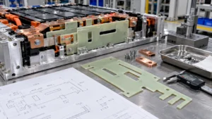
Six Industry Insights for FR4 Busbar Barrier Design
Insight 1 — Convert electrical requirements to geometry. Approved isolation targets must appear as identifiable conductor-to-edge, opening or surface relationships on the drawing.
Insight 2 — Functional datums beat blanket precision. Tight perimeter tolerances cannot compensate for location from the wrong face or hole; inspect what positions the barrier.
Insight 3 — Cutouts change three systems. A hole or slot alters electrical geometry, mechanical section and CNC feasibility, so review these together.
Insight 4 — Machinable is not necessarily robust. Thin fingers may cut successfully in one sample yet chip in production or assembly; evaluate the process chain.
Insight 5 — Edge and cleanliness criteria must be functional. Specify which defects and residues are unacceptable at critical electrical or locating interfaces.
Insight 6 — Assemblies reveal hidden variation. Real washers, fastener access, bracket position and busbar tolerances often expose risks invisible in isolated 2D part drawings.
Engineering Design Checklist for CNC-Machined FR4 Busbar Barriers
Use this checklist before authorizing a production drawing:
- Application and electrical boundary: pack/module location; busbar assembly model; conductive potential map; working and transient voltages; intended isolation paths; approved creepage/clearance targets; nearby grounded metal.
- Material and packaging: FR4 grade and supplier; candidate thickness and thickness tolerance; environmental range; available envelope; flatness and support condition; any severe thermal or fault-event exposure requiring a different barrier architecture.
- Coverage and profile: busbar-edge coverage; terminal and connector envelopes; necessary extensions; assembly access; outer perimeter; mounting tabs; remaining sections and vulnerable protrusions.
- Features: locating scheme; hole sizes and positions; fastener heads, washers, inserts and bushings; slots; cutouts; busbar pass-throughs; internal radii; narrow ligaments; tool access.
- Drawing controls: functional datums; electrical-critical dimensions; assembly-critical dimensions; general profile tolerances; thickness/flatness criteria; revision and inspection method.
- Production and release: CNC drilling/routing review; edge chipping and delamination criteria; cleaning; inspection evidence; prototype installation; tolerance stack-up; electrical, mechanical and environmental validation plan.
RFQ Checklist: What to Send a CNC FR4 Supplier
An actionable quotation package should contain a 2D PDF plus DXF/DWG where available, a 3D CAD part and busbar assembly, the installation location, and a clear description of the barrier’s function. Specify the chosen FR4 grade and thickness—or provide operating, electrical, and mechanical requirements if material selection is not finalized.
Include the overall profile, hole pattern, locating features, slots, cutouts, internal-corner requirements, datum system, critical tolerances, fastener and washer/bushing details, adjacent metal geometry, and relevant electrical separation targets. Also identify environmental conditions, edge condition, cleanliness, inspection expectations, prototype quantity, annual volume, and required validation responsibilities. An RFQ reading only “custom FR4 board” cannot support a defensible DFM review or accurate comparison of supplier proposals.
How Boost Insulation Can Support a Custom Barrier Project
Boost Insulation describes design-for-manufacturing review and precision CNC processing within its EV battery module insulation offering. For a CNC-machined FR4 busbar barrier inquiry, the useful first discussion is the customer’s busbar assembly, desired material specification, geometry, manufacturing constraints, and inspection expectations—not a promise that any FR4 plate will meet system voltage or safety requirements. See its EV battery module insulation capability overview: https://boostinsulation.com/products/ev-battery-module-insulation/.
A practical collaboration path is send the busbar assembly and preliminary FR4 drawing → review material and geometry → discuss CNC/DFM issues → make prototype parts → complete customer-controlled fit and electrical validation → release the approved production drawing. The final insulation-coordination targets, vehicle-level compliance, and system validation remain the responsibility of the designated design authority. Project teams can initiate a drawing-based inquiry through https://boostinsulation.com/contact/.
Frequently Asked Questions
1. How do you design a CNC-machined FR4 busbar barrier?
Start with the actual busbar assembly and identify every conductor, enclosure surface and mounting feature relevant to isolation. Define approved electrical boundaries, then develop the FR4 profile, coverage, holes, slots, and cutouts. Choose functional datums, assign critical tolerances, and review CNC access, edges and workholding. After machining, inspect dimensions and cleanliness and validate the prototype in the installed high-voltage assembly—not simply on a flat bench.
2. What information is needed before creating an FR4 barrier drawing?
The designer needs busbar and adjacent-metal geometry, conductor potentials, electrical isolation requirements, installation direction, fastener details, available space, and the barrier’s intended function. A candidate FR4 grade and thickness, environmental conditions, assembly stack-up, and verification requirements are also important. Missing information should be identified as an open design input rather than silently replaced by a generic creepage, clearance, material property, or hole-size assumption.
3. How should mounting holes be positioned in an FR4 busbar barrier?
Position holes from the functional assembly locating scheme, then check the installed hardware envelope against nearby conductors and insulating surfaces. Separate holes that locate the plate from those intended only for fastener clearance. Evaluate the remaining laminate, hole-edge condition, washer footprint, and assembly tolerances. The correct diameter, edge distance, and position tolerance depend on the fastener design, material, mechanical loads, and electrical architecture.
4. Can slots and cutouts affect FR4 busbar insulation?
Yes. Slots and cutouts remove material, change local stiffness, and may change the geometry of surface or air insulation paths. Their electrical effect depends on the applicable insulation-coordination rules, actual conductor positions, contamination conditions, and installed assembly. They also create CNC corner and handling requirements. Approve a slot for a defined function and verify its effect rather than assuming it always improves insulation simply by making the path look longer.
5. Why do internal corner radii matter in CNC-machined FR4?
A conventional rotating router leaves a radius at an internal corner, so an infinitely sharp CAD vertex is not a realistic standard machining requirement. Corner geometry also influences the remaining section, tool access, and stress concentration. A manufacturable radius or relief should be agreed with the mating-part designer. Its size is tooling- and geometry-dependent, not a universal rule applicable to every laminate thickness or busbar barrier.
6. Which FR4 barrier dimensions need tight tolerances?
Prioritize dimensions that control the installed isolation boundary and physical fit: locating patterns, hole-to-conductor relationships, terminal windows, and electrically important edges. Material thickness or flatness may also be critical when they affect a stack or separation. Cosmetic perimeter features can often follow general tolerances. Set limits using the complete assembly tolerance analysis and the supplier’s validated capabilities rather than imposing one tight value on the entire drawing.
7. How does CNC machining affect FR4 edge quality?
Routing and drilling expose the glass-epoxy laminate and can introduce chipping, rough fibers, or local delamination if the process and workholding are unsuitable. Tool wear, geometry, and support affect the results. Defects must be judged by their location and severity: not every rough edge causes electrical failure, but damage near critical features deserves review. Specify finished-edge acceptance and cleaning expectations, then inspect the parts against those requirements.
8. How should engineers validate a finished FR4 busbar barrier?
First confirm material identification, thickness, locating features, holes, slots, critical distances, edge condition, and cleanliness. Install the part with representative busbars, brackets, fasteners, and adjacent metal to verify fit and insulation geometry. Then perform application-specific electrical and mechanical tests, plus environmental evaluation where required. Dimensional compliance alone is insufficient; the relevant system engineer must approve the assembled insulation design and acceptance criteria.
Conclusion: Design for the Installed Barrier, Not Just the Machined Shape
CNC-machined FR4 busbar barriers succeed when electrical requirements become explicit geometry, the drawing locates that geometry from functional datums, and machining produces inspectable features without unacceptable damage. Profiles, holes, slots, fasteners, thickness, tolerance stack-up, edges, and cleanliness all influence the installed result. FR4’s datasheet is an input; it cannot substitute for part-level quality or assembly validation.
Send your busbar assembly and FR4 part drawing to Boost Insulation for a geometry and manufacturability review. Include the specified electrical isolation boundaries, grade or material requirements, thickness, holes, slots, cutouts, datums, critical tolerances, edge and cleanliness criteria, prototype quantity, and annual demand. The practical next step is a DFM-informed prototype that your engineering team can inspect and validate in the real assembly.
Related Posts:
Why Does Mica Insulation Survive High Heat in EV Batteries?

What is UL94 V0? Guide to Flame Retardant PC Film Testing
What Is Flame Retardant Polycarbonate and Why Does It Matter?
Should EV Battery Aerogel Pads Wrap or Split at Corners?
What Are EV Battery Module Solutions and How Do They Work?
Why EV Battery Modules Need Specialized Insulation?
 betty wong
