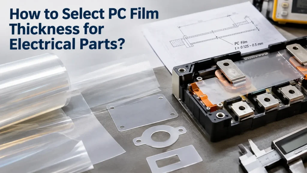
How to Select PC Film Thickness for Electrical Parts?
Table of Contents
A design engineer specifying a barrier must choose a PC film gauge that maintains separation, fits the package, and resists handling, heat, and flame exposure. A catalog choice or simple dielectric calculation does not resolve the full design problem.
⚑ QUICK ANSWER
What Is PC Film Thickness and Why Does It Matter for Electrical Parts?
PC film thickness is the gauge of a thermoplastic sheet, expressed in micrometers or millimeters. In electrical parts, film can serve as a dielectric barrier, spacer, separator, or cover. Gauge affects insulation path, stiffness, puncture resistance, handling, and converting.
Thickness alone does not define insulation performance. A finished part can fail because of damaged edges, contamination, poor fit, inadequate clearance, adhesive incompatibility, or unrepresentative testing. Specify PC film as part of the complete material-and-application system.
How Do Engineers Select PC Film Thickness for Electrical Insulation?
Start with the function the film must perform—not with a preferred catalog thickness. Identify whether it provides basic, supplementary, reinforced, or another defined insulation function under the applicable product safety framework. Establish working and transient stresses, operating environment, altitude where relevant, and the required solid-insulation performance.
Then compare candidate grades using current datasheets and certification records. Check minimum actual thickness, not only nominal gauge. Review mechanical support, temperature, flame behavior, adhesive construction, and die-cut geometry. The final selection should be validated against application-specific acceptance criteria.
Table 1 — PC Film Thickness Selection Factors
| Selection Factor | Engineering Requirement | Thickness Implication | Verification Method |
| Insulation function | Define the barrier’s role in the product | Sets design basis | Product safety review |
| Electrical stress | Identify working, transient, and test stresses | Affects solid insulation | Applicable standard and testing |
| Material grade | Confirm exact PC formulation and color | Grade properties vary | Current datasheet and certification |
| Minimum thickness | Define a lower limit if functionally required | Nominal may hide low gauge | Supplier tolerance data |
| Temperature | Define continuous and peak exposure | Aging may constrain grade selection | Thermal data and conditioned tests |
| Mechanical loading | Define bending, compression, puncture, and abrasion | Affects stiffness | Assembly evaluation |
| Flame requirement | Identify class and use thickness | Rating is grade/gauge-specific | Current certification record |
| Manufacturing | Define holes, slots, edges, and laminate | Geometry can limit gauge | Supplier DFM review |
Industry Insight 1 — Thicker PC Film Is Not Automatically Better
- Engineering observation: More thickness can improve some forms of puncture resistance and stiffness, but it increases stack height, material use, and bending resistance.
- Why it matters: A thicker film may interfere with fit, closure, or installation and can transfer load to adjacent parts.
- Practical recommendation: Compare electrical, mechanical, packaging, and converting consequences. Select the thinnest candidate that is validated for the application—not simply the thinnest available or the thickest that fits.
How Does PC Film Thickness Affect Electrical Insulation Performance?
More thickness increases the solid-insulation path, but allowable voltage does not rise proportionally. Performance also depends on grade, defects, electrodes, conditioning, temperature, aging, and installation.
Review bulk and surface risks separately. Strong through-thickness properties do not prevent tracking, contamination, edge flashover, or inadequate air spacing. Depending on the application, review dielectric strength, insulation resistance, CTI, arc resistance, or dielectric loss.
What Is the Difference Between Dielectric Strength and Breakdown Voltage?
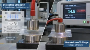
Dielectric strength is an electric-field value derived from a breakdown test, commonly expressed as voltage per unit thickness. Breakdown voltage is the voltage at which a particular specimen fails under defined conditions. Neither is automatically the continuous working-voltage rating of a finished assembly.
ASTM D149-25 covers test methods for dielectric breakdown voltage and dielectric strength of solid insulating materials at commercial power frequencies. ASTM cautions that test results seldom determine actual application behavior directly and should be evaluated with functional or other material tests. IEC 60243-1:2013 provides short-time electric-strength test methods at power frequencies.
Table 2 — Electrical Insulation Properties and Design Interpretation
| Property | What It Measures | Common Misinterpretation | Engineering Consideration |
| Dielectric strength | Breakdown field under a specified test | Treating it as continuous working voltage | Check method and conditions |
| Breakdown voltage | Voltage at failure for a specimen | Calling it safe voltage | Check test setup |
| Insulation resistance | Resistance to leakage current | Assuming withstand capability | Define voltage, time, and electrode arrangement |
| Dielectric constant | Relative permittivity | Treating it as insulation strength | Check capacitance needs |
| Dissipation factor | Dielectric energy loss | Ignoring frequency dependence | Check frequency |
| CTI | Resistance to tracking under a defined test | Treating it as through-thickness strength | Check surface and creepage |
| Arc resistance | Response to arcing under a specified test | Assuming it predicts every arc fault | Use if relevant |
A manufacturer datasheet illustrates the importance of test conditions. A 2020 LEXAN FR65 film datasheet reports dielectric strength for a 10 mil (0.25 mm) specimen tested in oil at 23°C using a short-time ASTM D149-97a Method A procedure. That is a material test result under a stated setup—not a working-voltage rating for a finished electrical assembly.
Industry Insight 2 — Dielectric Strength Is Not a Working-Voltage Calculator
- Engineering observation: Short-time breakdown tests characterize a specimen under controlled laboratory conditions.
- Why it matters: A simple operating-voltage divided by dielectric-strength calculation can omit transients, field concentration, aging, surface paths, and product-standard requirements.
- Practical recommendation: Use dielectric data to screen materials, then establish the design through the applicable product standard, safety analysis, and representative finished-part testing.
Can PC Film Thickness Be Calculated Directly from Operating Voltage?
No single voltage-to-thickness equation establishes a universally safe PC film gauge. A simplified field calculation may screen candidates, but it cannot replace insulation coordination or product-level verification because it omits field concentration, defects, manufacturing damage, environment, and the required insulation category.
IEC 60664-1:2020+AMD1:2025 addresses insulation coordination within its stated low-voltage equipment scope, including clearance, creepage, and solid-insulation criteria. Clearance is the path through air; creepage is the path along an insulating surface. Increasing film thickness does not automatically correct inadequate spacing.
Industry Insight 3 — Electrical Insulation Is a System-Level Design Problem
- Engineering observation: Electrical safety depends on solid insulation, air gaps, surface paths, interfaces, mounting, and environment.
- Why it matters: A thicker film cannot eliminate a contaminated surface path or insufficient air gap around a barrier edge.
- Practical recommendation: Review the complete insulation system and document barrier position, edge coverage, adjacent conductors, mounting, and spacing.
How Do Operating Temperature and Environmental Conditions Affect Thickness Selection?
Define continuous and peak temperature, thermal cycling, humidity, UV, cleaners, oils, and application chemicals. These exposures can affect dimensional stability, surface condition, retention, and long-term electrical performance.
Do not treat glass-transition temperature, Vicat softening temperature, or heat-deflection temperature as a continuous-use rating; they describe different test responses. Review grade-specific thermal data and any applicable RTI or end-use evaluation. Check chemical compatibility under the actual concentration, temperature, exposure time, and mechanical stress.
How Do Mechanical Requirements Influence PC Film Thickness?
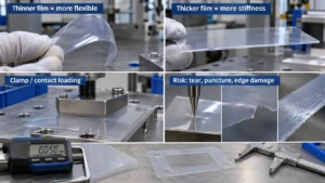
Mechanical requirements may set a practical lower limit even when a thin film appears adequate from electrical screening. The part may be handled, bent, clamped, compressed, vibrated, or exposed to abrasion. Evaluate the real support condition and the risk of puncture, tearing, creep, or edge damage.
Thickness changes flexibility. For an ideal isotropic plate, flexural rigidity is proportional to thickness cubed, so a modest gauge increase can make film substantially stiffer. Actual behavior also depends on grade, geometry, support, and temperature.
Table 3 — Thickness Trade-Off Matrix
| Thickness Consideration | Potential Benefit | Potential Limitation | Design Decision |
| Increased gauge | More physical separation and stiffness | More stack height and material use | Confirm assembly envelope |
| Reduced gauge | Better flexibility and lower profile | Greater sensitivity to handling damage | Validate puncture and robustness |
| Tight bend radius | Supports compact packaging if grade permits | Stress whitening, cracking, or spring-back | Review grade and bend method |
| Fastener contact | More material may resist local deformation | Clamp load can still cause damage or creep | Define contact and edge protection |
| Vibration | Stiffer barrier may hold shape | Load can transfer to mounting points | Evaluate retention and support |
Industry Insight 4 — Mechanical Geometry Can Change the Practical Thickness Requirement
- Engineering observation: A film that passes electrical screening can still tear at a slot, wrinkle during installation, or be damaged by a fastener.
- Why it matters: Mechanical damage can reduce the effective barrier or expose an unintended conductive path.
- Practical recommendation: Evaluate the real geometry, including cutouts, edges, bends, mounting pressure, and handling sequence.
How Do Flame-Retardant Requirements Affect PC Film Grade and Thickness Selection?
Flame-retardant performance is specific to the material and test specimen. UL 94 is a small-scale flammability test standard for polymeric materials used in parts of devices and appliances. UL describes separate classifications for materials and thin films; VTM classifications are used for thin materials that generally cannot support themselves in the horizontal test position. A VTM rating is not equivalent to the corresponding V rating.
Check the exact material designation, color, minimum thickness, and certification scope. Do not assume a grade rated V-0 at one thickness retains that rating at every thinner gauge. A current UL Product iQ record for specific LEXAN PC film/sheet grades lists different minimum-thickness entries for VTM-0 and V-0 classifications. This illustrates grade-specific listing conditions, not a universal PC thickness rule.
Table 4 — Application-Based PC Film Selection
| Electrical Application | Functional Requirement | Thickness Selection Driver | Validation Requirement |
| PCB or control-board barrier | Separate conductive features | Spacing, mounting, local heat, geometry | Product-standard review and electrical tests |
| Battery-module barrier | Dielectric separation in a constrained assembly | Electrical stress, edge coverage, abuse, flame requirement | Finished-part electrical and environmental validation |
| Power-electronics separator | Separation near heat-generating components | Thermal exposure, electrical stress, support | Thermal aging and electrical tests |
| Internal enclosure insulator | Prevent contact with conductive features | Fasteners, vibration, flame requirement, space | Fit, abrasion, and end-product evaluation |
| Terminal or lead cover | Cover a conductor while tolerating handling | Flexibility, puncture, bend radius, retention | Handling and dielectric verification |
| Die-cut insulating spacer | Maintain separation or position | Thickness tolerance, compression, cut geometry | Dimensional and assembly validation |
A UL 94 rating is not an electrical insulation certification. It does not establish dielectric withstand, tracking resistance, long-term electrical reliability, or complete end-product compliance.
Industry Insight 5 — Flame-Retardant Performance Must Be Verified at the Required Thickness
- Engineering observation: Flame classifications are associated with specific materials and test conditions, including thickness.
- Why it matters: A thinner film, different color, or different formulation may fall outside the certification scope.
- Practical recommendation: Obtain the current UL file for the exact grade, color, and minimum use thickness. Verify whether the application requires V, VTM, or another classification.
How Do Thickness Tolerances Affect Electrical Insulation Design?
Nominal thickness is the designated gauge; minimum actual thickness is the lowest permitted value under the agreed measurement method. If performance depends on a minimum barrier, a nominal value alone can leave acceptance ambiguous.
State nominal thickness, tolerance, minimum where required, measurement method, conditioning, and whether the value applies to base film or laminate. For coated or adhesive-backed constructions, contact pressure can affect measurement.
Link tolerance to function. A cover may accept a broad range, while a spacer or solid-insulation barrier may need tighter control. Identify critical characteristics and measurement method.
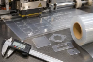
How Does PC Film Thickness Affect Precision Die Cutting?
Thickness influences cutting force, part stiffness, stripping, dimensional stability, and handling. Thin film may be more susceptible to stretching, static attraction, wrinkling, or distortion during web handling. Thicker film may require different tooling or process settings and can change the quality of small holes, narrow webs, and internal corners.
The converting process must match the exact film grade and geometry. Tooling method, support liner, adhesive stack, web tension, and part size all affect the result. A supplier should review the drawing and material construction before confirming feature feasibility or dimensional capability.
SABIC’s film technical manual describes die-cutting of thermoplastic films and notes that web tension can produce dimensional changes during roll-to-roll processing. It also discusses how part geometry and film thickness influence cutting outcomes. This is a process reference, not a universal capability specification for every converter or current grade. [8]
Table 5 — PC Film Thickness and Die-Cutting DFM
| Design Feature | Manufacturing Concern | Thickness-Related Risk | Supplier Review |
| Small holes | Feature definition and slug removal | Distortion or higher cutting load | Confirm feature feasibility |
| Narrow webs | Part integrity and handling | Tearing or stretching | Review minimum web and support |
| Sharp corners | Local stress and edge quality | Tear initiation | Review corner radius and tool strategy |
| Long narrow slots | Dimensional stability | Film movement during converting | Confirm registration |
| Large thin panels | Flatness and handling | Wrinkling, static, deformation | Review carrier and handling |
| Adhesive lamination | Bondline and liner control | Finished stack differs from base film | Define layer sequence |
| Tight tolerances | Tooling, movement, inspection | Gauge and web tension may affect geometry | Confirm capability and method |
Industry Insight 6 — DFM Should Be Completed Before Thickness Is Frozen
- Engineering observation: A gauge selected without reviewing holes, slots, narrow webs, adhesive, and handling may be difficult to convert consistently.
- Why it matters: A theoretically suitable film can produce unstable dimensions or damaged features after cutting and part removal.
- Practical recommendation: Review candidate gauges using the actual drawing and layer stack-up. Confirm geometry, edge requirements, tolerances, and inspection before production release.
Should Engineers Select PC Film Thickness Before or After DFM Review?
Thickness selection and DFM should be iterative. Engineering defines function and candidate grades; the supplier reviews availability, geometry, converting method, and dimensional capability. Resolve concerns before freezing the drawing.
The supplier identifies process constraints and quotation assumptions but should not change the insulation function. Approve any substitution or gauge change that affects safety or performance.
DFM Checklist for Custom Die-Cut PC Film Insulation Parts
- Exact PC grade identified.
- Nominal thickness and tolerance specified.
- Minimum actual thickness stated where required.
- Film surface and color identified.
- Bending and forming requirements defined.
- Holes, slots, and cutouts reviewed.
- Narrow webs and sharp corners reviewed.
- Critical dimensions and tolerances identified.
- Adhesive and liner construction specified.
- Orientation and surface-side requirements stated.
- Edge and particle requirements defined.
- Supplier confirms cutting feasibility.
- Prototype inspection criteria agreed.
How Should Engineers Evaluate Adhesive-Backed PC Film Construction?
For adhesive-backed PC film, distinguish base-film thickness from total laminate thickness. Adhesive, carrier, protective film, and release liner may affect bondline variation, dielectric behavior, flammability, chemical compatibility, and retention. A liner removed during installation is not a permanent insulation layer.
Specify layer order, material designations, adhesive coverage, liner type, exposed surfaces, and whether finished thickness includes removable layers. Verify the complete construction against temperature, humidity, chemical, and electrical requirements.
Industry Insight 7 — Finished-Part Performance Is Not Base-Film Performance
- Engineering observation: A base-film datasheet does not necessarily characterize the adhesive-backed or die-cut component.
- Why it matters: Added layers and converting can change the insulation path, edge condition, thickness, and adhesion.
- Practical recommendation: Validate the production-intent construction, including adhesive and liner where relevant.
How Does PC Film Thickness Selection Differ Across Electrical Applications?
Do not assume one gauge suits every part. Battery barriers may be driven by voltage stress, edge coverage, abuse, and flame requirements. Control-board spacers may depend on spacing and heat; terminal covers on flexibility and retention; enclosure insulators on fasteners, vibration, and impact. The application determines the relevant properties and tests.
How Should PC Film Thickness Be Specified on an Engineering Drawing?
Identify the exact material grade, nominal thickness, tolerance, minimum thickness if required, surface or color, and applicable certification condition. For a laminate, specify the full stack-up and which layers remain in the finished assembly. Define critical dimensions, edge requirements, orientation, and inspection method.
Avoid a note such as ‘0.25 mm PC, UL94 V-0′ unless the exact grade and certification record support that thickness. Reference the approved material designation and current certification record; separate product requirements from supplier process controls.
How Can Engineers Validate the Selected PC Film Thickness?
Validate the production-intent material and finished part against design requirements. Begin with material identity and thickness inspection, then select electrical, mechanical, thermal, environmental, and flame checks from the product standard and risk assessment. ASTM D149 and IEC 60243-1 are electric-strength references; IEC 60664-1 addresses insulation coordination within its scope; UL 94 addresses flammability, not complete electrical approval.
A risk-based plan may include thickness verification, visual inspection, dielectric withstand or breakdown testing, insulation resistance where relevant, thermal or humidity conditioning, dimensional inspection, puncture or abrasion checks, flame-classification verification, and assembly-level testing.
Define conditioning, electrodes, waveform, ramp or dwell time, environment, failure criteria, sample count, and acceptance limits from the applicable standard and product specification.
Industry Insight 8 — The Best Thickness Is a Validated Design Window
- Engineering observation: Datasheets and calculations narrow candidates but cannot reproduce every service condition.
- Why it matters: Material variation, tolerances, geometry, aging, and converting can change results.
- Practical recommendation: Freeze the gauge only after finished-part validation.
PC Film Thickness Selection Workflow
- Define application location.
- State insulation function.
- Record voltage and electrical stresses.
- Identify transients.
- Confirm safety requirements.
- Select PC grades.
- Review available gauges.
- Interpret dielectric data and test conditions.
- Define nominal gauge.
- Set tolerance and minimum thickness if required.
- Review temperature and aging.
- Review loading, bending, handling.
- Assess humidity, chemicals, UV, and aging.
- Confirm flame class at use thickness.
- Define adhesive and laminate stack.
- Complete supplier DFM review.
- Prototype and validate.
- Approve material, drawing, inspection, and controls.
Preliminary screening identifies candidates; final approval requires evidence that the finished component meets product requirements.
Hypothetical Engineering Example: Selecting PC Film Thickness for an Electrical Insulation Barrier
Hypothetical Engineering Example
An electronics manufacturer needs a die-cut PC barrier between conductive subassemblies. Package space is limited; the part must survive assembly handling and meet a flame requirement.
Define and screen: Document insulation function, electrical stresses, applicable product standard, and adjacent conductors. Compare grades using current dielectric, thermal, mechanical, and certification data. Do not convert dielectric strength directly into working voltage.
Compare and review: Check gauge options, tolerance, minimum actual thickness, stiffness, puncture resistance, fit, and adhesive stack. Ask the supplier to review holes, narrow webs, edge geometry, liner removal, and inspection.
Prototype and validate: Inspect production-intent samples for thickness, fit, edge quality, and handling. Select electrical and environmental tests from identified failure modes.
Datasheets identify candidate grades, reported properties, gauge options, and material-specific certification. Supplier confirmation is needed for availability, tolerances, laminate options, cutting feasibility, and inspection. Application testing must establish finished-part behavior and compliance.
This hypothetical example does not recommend a universal gauge. Approve thickness only after actual requirements and test results are reviewed.
Common PC Film Thickness Selection Mistakes
- Voltage-only sizing → Misses transients → Define full electrical stresses.
- Dielectric strength used as working voltage → Misuses test data → Apply product standards.
- Thicker assumed safer → Creates fit risks → Evaluate system trade-offs.
- Minimum gauge ignored → Film may be thinner → Specify a functional minimum.
- Temperature ignored → Aging risk → Review grade-specific thermal data.
- Chemicals or humidity ignored → Degradation risk → Check compatibility.
- PC grades treated alike → Properties differ → Specify exact grade.
- UL rating transferred across gauges → Scope mismatch → Check certification.
- Compression or abrasion ignored → Damage risk → Test actual mounting.
- Creepage and clearance ignored → Spacing risk → Review full insulation system.
- Adhesive or liner omitted → Stack-up unclear → Specify all layers.
- Gauge frozen before DFM → Feature risk → Review actual drawing.
- Unrealistic tolerances assigned → Inspection risk → Agree measurable limits.
- Base and laminate thickness confused → Stack-up error → Define measured layers.
- One datasheet value used → Failure modes missed → Review relevant properties.
- Product standard ignored → Compliance gap → Identify standard early.
- Finished-part tests skipped → Converting defects missed → Validate samples.
- Grade and tolerance omitted → Substitution risk → Control material designation.
- Supplier feasibility assumed → Process risk → Obtain DFM confirmation.
- Production released early → Unverified assumptions → Approve sample and revision.
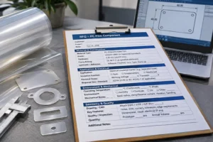
What Information Should Be Included in a PC Film RFQ?
A useful RFQ gives the supplier enough information to identify the material, understand the electrical function, review geometry, and define quotation assumptions. A nominal thickness or screenshot alone is not enough for a meaningful manufacturing review.
Table 6 — PC Film Material Specification and RFQ
| Required Information | Customer Input | Supplier Confirmation | Technical Risk |
| Application | Part function and installation location | Application understanding | Wrong material assumptions |
| Electrical requirement | Insulation function and relevant stresses | Data availability and review scope | Misuse of dielectric data |
| PC grade | Exact grade or approved-equivalent criteria | Grade availability | Unverified substitution |
| Thickness | Nominal, tolerance, minimum if needed | Available gauge and tolerance | Underspecified barrier |
| Flame requirement | Classification and required use thickness | Certification scope | Rating not valid at gauge |
| Environment | Temperature, humidity, chemicals, UV | Compatibility questions | Premature degradation |
| Laminate | Adhesive, facing, carrier, liner | Layer compatibility | Stack-up mismatch |
| CAD / drawing | Accepted CAD and approved PDF | Geometry review | Quotation ambiguity |
| Quality | Inspection method and acceptance criteria | Measurement feasibility | Disputed acceptance |
| Quantity | Prototype and annual volume | Quotation basis | Incomplete commercial scope |
RFQ Checklist for Custom PC Film Electrical Insulation Parts
Customer should provide:
- Electrical application and insulation function.
- Operating conditions and relevant electrical stresses.
- Applicable safety and flame-retardant requirements.
- Preferred PC grade or approved-equivalent criteria.
- Nominal thickness, tolerance, and minimum where required.
- CAD drawing and approved PDF.
- Adhesive and laminate construction.
- Critical dimensions and inspection requirements.
- Prototype quantity and annual production forecast.
Supplier should confirm:
- Material grade and availability.
- Current datasheet and certification scope.
- Thickness options and tolerances.
- DFM and die-cutting feasibility.
- Lamination compatibility.
- Dimensional capability and inspection method.
- Prototype plan and validation responsibilities.
- Open engineering questions and quotation assumptions.
How Can Boost Insulation Support Custom PC Film Insulation Components?
Boost Insulation’s flame-retardant polycarbonate page describes PC sheets and films, material-grade and thickness review, DFM support, and custom cutting, forming, and laminating with adhesives or protective films. It invites customers to submit designs for manufacturability review and quotation.
A dedicated ‘UL94 V0 PC Films‘ page is also published, but its visible specification content does not expose grade-specific thickness ranges or dielectric values. Request the current material designation, datasheet, tolerance, and certification record before approving a grade.
For an RFQ, provide the application, insulation function, operating conditions, flame requirement, candidate gauge, drawing, and tolerances. Confirm grade, thickness, process route, and prototype scope.
Suggested Boost Insulation Resources
- Flame Retardant Polycarbonate — PC material and DFM information.
- UL94 V0 PC Films — dedicated product page; request grade-specific documentation.
- About Boost Insulation — precision die-cutting and functional-material overview.
- What’s the Difference Between FR-PC and Standard PC? — related flame-retardant PC background.
- How to Choose EV Battery Cell Insulation Pads — broader battery insulation context.
- Contact Boost Insulation — submit a project inquiry.
Industry Insight 9 — The Best RFQ Minimizes Engineering Assumptions
- Engineering observation: A drawing without a grade, tolerance, flame requirement, or test basis forces the supplier to make assumptions.
- Why it matters: Those assumptions can create quotation exclusions or prototype mismatches.
- Practical recommendation: Submit the material requirement, finished-part drawing, application conditions, and acceptance criteria together. Ask the supplier to list any remaining assumptions in the quotation.
Request a PC Film Thickness and DFM Review for Custom Electrical Insulation Parts
PC film thickness must balance electrical performance, mechanical protection, thermal exposure, flame requirements, dimensional control, and manufacturability. Final approval requires exact grade documentation and finished-part validation.
Prepare the application, insulation function, operating conditions, safety requirements, preferred grade, candidate gauge, CAD/PDF drawings, laminate construction, critical tolerances, and prototype and annual volumes.
Workflow: Electrical Requirements + Material Specification + CAD Drawing → Thickness and DFM Review → Prototype Quotation → Application-Specific Validation → Material Approval.
Submit the requirements and drawing package through Boost Insulation Contact.
Frequently Asked Questions
1. How do I choose the right PC film thickness for electrical insulation?
Define the insulation function, electrical stresses, product standard, and environment. Compare exact PC grades using current dielectric, thermal, mechanical, and flame documentation. Check nominal and minimum thickness, tolerance, and laminate construction. Confirm manufacturability and validate the finished part. before production release
2. Does thicker polycarbonate film provide better electrical insulation?
Greater thickness increases the solid dielectric path, but does not automatically make the design safer. Performance also depends on grade, defects, surface condition, temperature, aging, and spacing. Thicker film may be harder to fit or convert. Select from requirements and validation.
3. Can I calculate PC film thickness from dielectric strength?
A simplified calculation may screen candidates, but cannot establish safe working thickness. Dielectric strength is measured under specified test conditions, not as a continuous service-voltage rating. Consider transients, field concentration, insulation coordination, aging, environment, and product requirements. in the final assembly
4. What is the difference between dielectric strength and breakdown voltage?
Breakdown voltage is the voltage at which a specimen fails under defined conditions. Dielectric strength expresses the breakdown field, often normalized by thickness. Both depend on method, electrodes, conditioning, temperature, and medium. Neither is automatically the allowable operating voltage. in the actual product
5. Does PC film thickness affect UL 94 flame-retardant classification?
Yes. UL 94 classifications apply to specific materials and test conditions, including thickness. A grade may have different minimum thicknesses for VTM and V categories. VTM is not equivalent to V. Verify the current record for exact grade, color, and use thickness.
6. How does PC film thickness affect precision die cutting?
Thickness affects cutting force, stiffness, web handling, stripping, edge quality, and stability. Thin films may stretch or wrinkle; thicker films may need different tooling or settings. Ask the supplier to review the drawing, grade, laminate, and tolerances. for the selected application
7. What thickness tolerance should be specified for PC insulation film?
Specify nominal thickness and a tolerance supported by the selected grade and supplier. If performance depends on a lower bound, define minimum actual thickness and a measurement method. State whether it applies to base film or laminate. Confirm availability and inspection capability.
8. What information should I send to a supplier for custom die-cut PC film insulation parts?
Provide application, insulation function, operating conditions, safety requirements, PC grade, thickness, flame requirement, and environment. Include CAD, approved PDF, laminate construction, critical dimensions, tolerances, inspection criteria, prototype quantity, and annual forecast. Request DFM and certification confirmation. and quotation assumptions for quotation
Related Posts:
Which Aerogel Grade Is Best for High-Voltage EV Cells?
How Much Delay Can an Aerogel Barrier Provide in EV Packs?
Why EV Battery Modules Need Specialized Insulation?
How Does Flame Retardant Polycarbonate Compare to FR ABS Plastic?
Which Insulation Material Is Best Under EV Pack Covers?
How Is a Mica Insulation Sheet Used on Module End Plates?
 root