
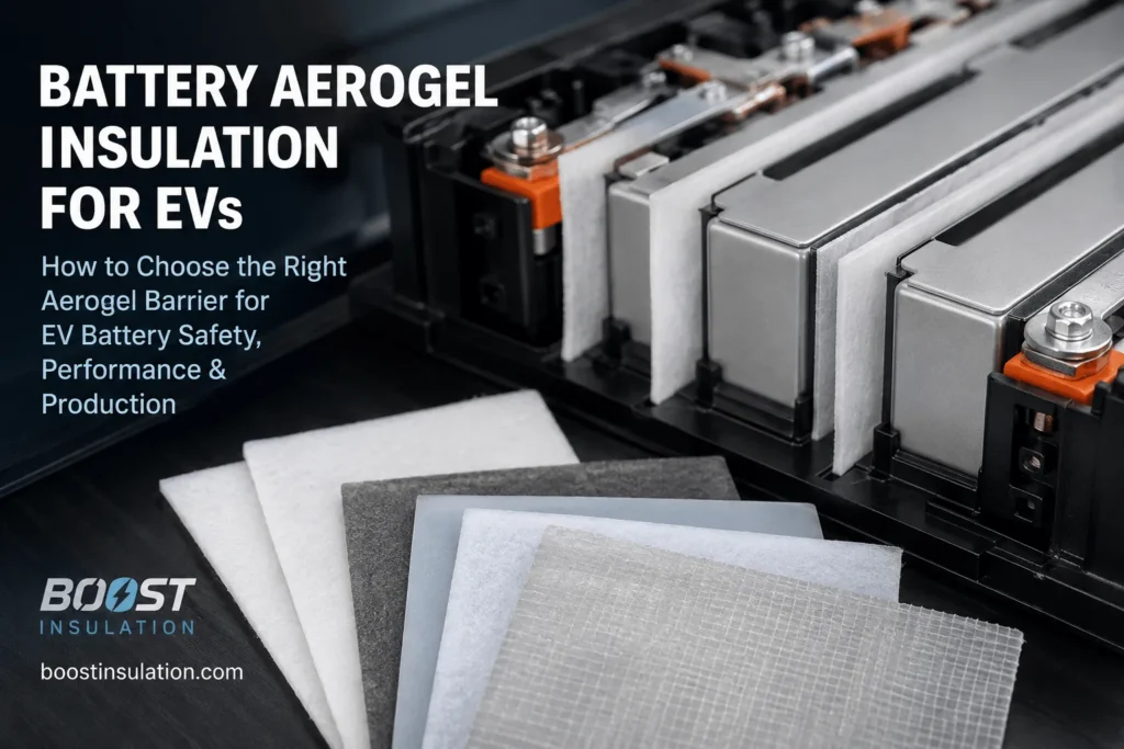
How Do You Choose Battery Aerogel Insulation for EVs?
Table of Contents
A thin white pad may look like the simplest component in an EV battery module, but selecting the wrong one can create a serious design problem: too little thermal resistance, excessive stack pressure, damaged cell surfaces, blocked venting, or a barrier that performs well in a datasheet and poorly in the assembled pack. So how do you choose aerogel insulation that protects the next cell without compromising cooling, compression, electrical safety, or mass production?
| Featured Snippet Answer: Choose battery aerogel insulation for EVs by first defining the required safety function and module-level test target, then matching the aerogel grade, installed thickness, compression range, high-temperature integrity, dielectric properties, encapsulation, adhesive, and die-cut geometry to the cell format and vent path. Validate the finished converted part under representative compression and thermal-runaway conditions; do not select it from room-temperature conductivity alone. |
Battery Aerogel Insulation for EVs: Selection at a Glance
| Selection Area | What to Define | What to Validate |
| Safety function | Delay, no propagation, temperature limit, dielectric or flame protection | Module and pack pass criteria |
| Installed geometry | Cell format, coverage, vents, thickness, compression, edge design | Representative assembly and aging |
| Finished construction | Aerogel, film, reinforcement, adhesive, liner, PC, foam, or mica | Complete converted-part performance |
| Supplier capability | DFM, cleanliness, traceability, PPAP, prototypes, and change control | Repeatable volume production |
How to Choose Battery Aerogel Insulation for EVs
The correct selection process begins with the battery architecture, not with a generic aerogel datasheet. Aerogel is used because its porous structure can provide high thermal resistance in a limited space, but the finished intercell part may also need to manage electrical isolation, swelling, vibration, vent exposure, dust, adhesive placement, assembly speed, and long-term compression.
A responsible engineering specification therefore connects material properties to a measurable system outcome. The outcome may be a minimum delay before adjacent-cell thermal runaway, no propagation during a defined observation period, a maximum protected-cell surface temperature, or protection of a module wall, busbar, cooling line, or pack cover.
No supplier can provide one universal grade that is correct for every EV platform. Cell chemistry, state of charge, cell capacity, format, vent direction, facing area, stack pressure, cooling strategy, electrical configuration, enclosure design, and abuse-test method all change the required barrier.
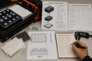
Battery Aerogel Insulation for EVs Starts With the Safety Goal
Before discussing thickness or price, define what the aerogel must do. Four functions are commonly confused: normal thermal management, cell-to-cell propagation control, electrical insulation, and flame or jet protection.
Normal thermal management removes routine operating heat through thermal pads, gels, cooling plates, refrigerant channels, and heat spreaders. Aerogel performs the opposite function: it resists unwanted heat flow. It should not be placed across an intended cell-to-cold-plate cooling path unless the pack design specifically requires local isolation.
Cell-to-cell propagation control aims to slow or prevent energy transfer from a failing cell to its neighbor. Electrical insulation prevents contact between conductive surfaces and maintains dielectric separation. Direct flame or vent-jet protection may require a high-temperature facing, mica, ceramic fabric, or a dedicated shield in addition to aerogel.
Translate the safety goal into a testable statement. For example: “No adjacent-cell thermal runaway for 300 seconds after confirmed trigger-cell runaway,” or “The protected cell surface remains below the project-defined threshold during the module test.” This is more useful than writing “use 2 mm aerogel” without a performance basis.
Match Battery Aerogel Insulation for EVs to Cell Format
Prismatic cells typically present a large flat heat-transfer surface. Near-full-face aerogel barriers are a strong starting point because they interrupt conduction and radiation across the dominant interface. The profile must avoid terminals, welds, sensing features, safety vents, cooling contacts, module rails, and required creepage distances.
Pouch cells also use broad-face barriers, but their flexible packaging and swelling behavior make pressure uniformity critical. The aerogel should avoid hard steps, thick film overlaps, adhesive ridges, and poorly positioned pull tabs. A compliant silicone foam layer may be added to manage stack variation, but it must not over compress the aerogel.
Cylindrical modules often need row barriers, group partitions, sleeves, or module-boundary shields rather than one rectangular pad between every pair of cans. Open channels between cylinders can carry hot gases and flame, while busbars and cell holders can bypass the insulation. Vent direction and top-cover protection may dominate the design.
Cell-to-pack and cell-to-chassis architectures reduce traditional module boundaries. They can increase the value of thin, high-performance barriers, but they also create long structural heat paths through trays, cooling plates, cross-members, and adhesives. Selection must be coordinated earlier in the platform design.
Choose Battery Aerogel Insulation for EVs by Thermal Performance
Thermal conductivity is an important screening property, but a single room-temperature number is not enough. Ask how the value was measured, at what mean temperature, in which direction, at what density, at what pressure, and whether the reported value belongs to the bare aerogel core or the complete laminate.
Through-plane performance is usually the main concern for a flat intercell pad. Elevated-temperature behavior matters because thermal-runaway exposure is far beyond normal pack operating temperature. Radiation can become increasingly important at high temperature, and the surface film, adhesive, or reinforcement may control performance before the aerogel core reaches its limit.
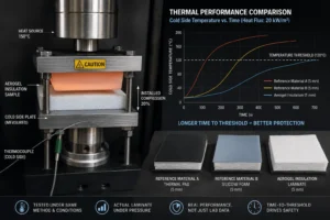
Compare materials under the same test method and conditions. A lower nominal conductivity measured on a thick, uncompressed laboratory specimen may not outperform a slightly higher value measured on the actual converted laminate under installed pressure.
Request cold-side temperature curves or heat-flux test results when possible. These show how quickly the protected surface heats and whether the barrier maintains its structure. For a project decision, time-to-threshold data is often more useful than one conductivity number.
Battery Aerogel Insulation for EVs Needs the Right Thickness
Thickness normally increases thermal resistance and can increase propagation delay. Published battery experiments using different aerogel-felt thicknesses have shown that thicker barriers can materially delay downstream-cell thermal runaway. Those results demonstrate the trend, not a universal thickness rule for EV modules.
The correct design value is installed thickness after assembly, not free-state thickness from the incoming-material certificate. Module preload, cell tolerance, aerogel tolerance, frame tolerance, temperature, aging, and end-of-life swelling can change the final value.
Define a compression window. A nominal pad may be acceptable at beginning of life but become too thin as cells swell. Excessive compression can increase solid contact, reduce the thermal path length, damage the porous structure, and create adhesive squeeze-out. Insufficient compression can allow gaps, wrinkles, or movement.
Thickness should be selected through an iterative process: screen candidate materials, test the finished laminate under representative pressure, prototype the module stack, measure pressure and temperature distribution, and confirm performance in abuse testing. The minimum validated thickness with manufacturing margin is usually a better commercial target than the maximum thickness that fits.
Evaluate Compression and Mechanical Durability
Battery aerogel parts must survive years of vibration, thermal cycling, humidity, and cell dimensional change before they are ever exposed to a thermal event. Mechanical weakness is therefore a safety and manufacturing issue, not merely a handling inconvenience.
Request compressive stress-strain data, compression set, thickness recovery, tensile strength, flex durability, edge integrity, and aging results. For pouch and prismatic stacks, understand the pressure range at beginning of life and end of life. For cylindrical modules, review how the barrier is supported so that it cannot sag into cooling or vent channels.
A reinforced carrier felt, scrim, film, or rigid protective layer can improve dimensional stability. However, reinforcement also changes thermal performance, thickness, flame behavior, cost, and cutting response. The qualification unit should be the exact multilayer construction intended for production.
Inspect prototype parts after assembly trials. Look for crushed edges, local thinning, folds, liner fragments, exposed powder, adhesive transfer, surface marks on the cell, and movement after vibration. These defects frequently reveal risks that coupon testing cannot show.
Choose Battery Aerogel Insulation for EVs by Heat Resistance
A high service-temperature claim should be separated into several questions. Does the aerogel core remain stable? Does the carrier shrink? Does the encapsulation film melt or retract? Does the adhesive soften, flow, ignite, or release the part? Does the edge seal open and allow hot gas to enter the laminate?
Ask for high-temperature dimensional stability, mass loss, shrinkage, cold-side temperature, and post-exposure integrity. If the part faces direct flame or a vent jet, use an impingement test or a representative cell test rather than relying only on a hot-plate test.
The hot-side surface may require mica, coated glass fabric, ceramic paper, PI film, or another high-temperature facing. Aerogel can then provide the principal thermal resistance behind the protective layer. The facing should distribute local heat and particle impact without becoming a conductive bridge.
Do not confuse a short-term peak-temperature claim with continuous service capability. A material may survive a brief high-temperature event but be unsuitable for long-term operation at that temperature. The supplier should state the basis and duration of every temperature rating.
Check Electrical Insulation and Flame Classification
Some aerogel laminates can contribute electrical insulation, but not every aerogel product should be treated as a certified dielectric barrier. The construction may contain conductive additives, foil layers, carbon-based opacifiers, exposed fibers, surface contamination, or thin regions that affect electrical performance.
When electrical isolation is required, specify dielectric strength, insulation resistance, dielectric breakdown after aging, moisture conditioning, and performance at the minimum installed thickness. Evaluate cut edges, holes, adhesive zones, and metal contact points—not only the center of the sheet.
Flame classifications should also be interpreted carefully. UL 94 V-0 and VTM-0 are small-scale material classifications performed under defined specimen conditions. The rating depends on the material, thickness, orientation, and test method. VTM-0 is not equivalent to V-0, and neither rating proves resistance to a battery jet flame or pack-level non-propagation.
Verify the exact grade, thickness, color, film, adhesive, and supplier documentation. A certificate for the aerogel core does not automatically cover the converted multilayer part. If flame performance is a project requirement, test or document the finished construction at the relevant thickness.
Select Encapsulation for Battery Aerogel Insulation for EVs
Encapsulation can reduce particulate release, improve handling, protect the core from abrasion, and create a cleaner dielectric surface. Common constructions use PET, PI, coated glass fabric, scrim, or custom multilayer facings depending on temperature, flexibility, electrical, and flame requirements.
The film should be selected for the actual location. PET may support routine handling and dielectric functions in moderate exposure areas. PI or higher-temperature facings may be more appropriate near vent zones. Mica or ceramic-facing layers may be required for direct flame impingement.
Review film shrinkage, puncture resistance, folding behavior, chemical compatibility, and adhesion to the aerogel. A film that retracts during heat exposure can uncover the core or create an edge opening. A brittle facing can crack during die cutting or assembly.
Define the edge construction. Exposed edges may release dust, absorb contamination, or allow hot gas into the laminate. A sealed edge improves handling, but an overly wide polymer seam may reduce the active aerogel area or create a heat bridge. Edge-seal material, width, overlap, and orientation should be controlled on the drawing.
Choose Adhesive Without Creating a Thermal Bridge
Adhesive backing can improve assembly speed, positioning, and automation, but it changes the thermal and mechanical stack. Full-face pressure-sensitive adhesive creates a continuous polymer layer and increases contact over the entire barrier. Depending on the formulation, it may alter thermal resistance, compression, flame behavior, and long-term adhesion.
Use adhesive only where it is needed. Perimeter strips, small registration zones, or one-sided selective adhesive can hold the part while leaving more active aerogel area. The best pattern depends on the assembly sequence, cell surface, vibration, compression, and contamination requirements.
Specify peel strength after heat aging, humidity, electrolyte exposure, and compression cycling when relevant. Review liner release force, pull-tab design, adhesive squeeze-out, and repositionability. An adhesive that bonds strongly in a room-temperature peel test may fail on a low-surface-energy cell coating or after long-term heat exposure.
Keep adhesive away from vents, terminals, welds, cooling contacts, and high-temperature edges unless the exact construction has been validated. The finished die-cut part—not the adhesive datasheet alone—should be tested.
Design Battery Aerogel Insulation for EVs Around Vents
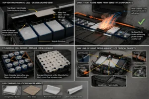
A pressure-relief vent must remain functional. Aerogel should protect the surface receiving the heat without blocking the outlet. For a top-venting prismatic cell, the broad-face intercell barrier often stops below the vent while a separate top shield or vent guide controls the plume.
Hot gas, flame, electrolyte droplets, and particles can travel around a flat barrier much faster than heat conducts through it. Map line-of-sight paths to the neighboring cell shoulder, terminals, busbar, plastic holder, lid, and electronics. Add shaped extensions, local mica, flame-resistant covers, or vent channels where needed.
Cylindrical-cell arrays require special attention to the open channels between cans. Gas can travel through the triangular voids even when contact points are insulated. Row partitions and under-lid protection may provide more value than small contact patches.
The vent path should direct products toward a space or relief feature that can tolerate pressure, heat, particles, and possible ignition. A barrier should never create a dead end that redirects the event toward another cell.
Control Metallic and Structural Heat Bypasses
A cell-to-cell aerogel pad may perform well while the module still propagates through a metal bridge. Busbars, side plates, end plates, cooling plates, bolts, welds, cell cans, and structural frames can carry energy around the barrier.
Use thermal mapping and instrumentation to identify the real bypass. Flame-retardant polycarbonate insulation can separate metal surfaces and provide puncture-resistant dielectric coverage. Mica can protect locations exposed to intense flame or arcs. Insulated fasteners, slots, geometric breaks, coatings, or lower-conductivity structural components may be required.
Cooling plates deserve particular attention. They are designed to spread and remove normal heat, but during thermal runaway they may also distribute energy. The correct response may be active coolant flow, local isolation, segmented plate design, or a combination of passive and active measures.
Do not assume that adding more aerogel at the broad face will fix a dominant metal path. The system should be redesigned where the energy actually travels.
Combine Aerogel With PC Insulation, Silicone Foam, and Mica
No single material performs every battery function efficiently. Aerogel offers high thermal resistance in a thin envelope. Flame-retardant polycarbonate provides structural dielectric isolation, puncture resistance, clean surfaces, and shaped tabs around high-voltage components. Silicone foam manages gap variation, vibration, swelling, and preload. Mica provides high-temperature electrical and flame protection.
A hybrid intercell stack may use aerogel as the thermal core, a thin dielectric film or PC layer as mechanical protection, and silicone foam in selected pressure-management zones. At vent corridors, module boundaries, or under the pack cover, mica or a flame-resistant facing may be added.
Layer order matters. The jet-facing side may need the most heat-resistant surface. The cell-facing side may need compliance and smoothness. The structure-facing side may need puncture resistance and dielectric stability.
Every added layer creates tolerance, cost, adhesive interfaces, and possible heat paths. Use the simplest stack that meets the validated functions. Test the assembled multilayer part at the intended pressure.
DFM for Die-Cut Battery Aerogel Insulation for EVs
A production aerogel barrier is a converted component, not a rectangular material sample. The converter needs the cell outline, active face, vent keep-out, terminal and weld geometry, frame features, cooling interface, assembly direction, compression range, and protected surfaces.
Critical drawing requirements include overall profile, installed thickness, thickness tolerance, edge-seal width, vent clearance, top-edge height, adhesive zones, liner split, pull tabs, cutout radii, locating holes, minimum web width, flatness, cleanliness, packaging orientation, and special-characteristic markings.
Aerogel can be crushed, torn, or contaminated during slitting and die cutting. Tool clearance, blade condition, cutting pressure, support liner, web tension, dust extraction, handling, and inspection need process control. Broken encapsulation or exposed powder can affect handling, cleanliness, dielectric performance, and effective coverage.
Prototype tooling should support rapid design iteration. Flatbed, digital, rotary, or progressive die cutting may be selected according to geometry, material construction, volume, and tolerance. Production feasibility should be reviewed before the module test so that the validated design can be manufactured consistently.
Validate Battery Aerogel Insulation for EVs at Five Levels
Level 1- is material and laminate screening. Measure thickness, density or areal weight, thermal conductivity, high-temperature shrinkage, compression behavior, dielectric properties, flame response, adhesive peel, dust, moisture, and chemical compatibility.
Level 2- is thermal coupon testing. Test the complete stack under representative compression with a hot plate, heat-flux source, radiant exposure, or burner. Compare cold-side temperature, time to threshold, film damage, edge penetration, and residual integrity.
Level 3- is interface or two-cell testing. Reproduce cell geometry, pressure, vent direction, busbars, cooling contacts, and edge conditions. Instrument the broad face, shoulder, terminals, barrier edge, and likely bypass paths.
Level 4- is module propagation testing. Trigger the selected cell using the project-defined method and worst credible state of charge. Record trigger-cell runaway, adjacent-cell temperature and voltage, venting, flame, gas, pressure, electrical isolation, warning signals, and propagation time.
Level 5- is pack or vehicle validation. Confirm the full warning strategy, enclosure response, controlled venting, external hazard criteria, electrical safety, and post-event condition. UN Regulation No. 100 evaluates thermal-propagation safety at the REESS or vehicle level; a material certificate alone cannot establish compliance.
Repeat relevant tests after aging, vibration, humidity, compression cycling, chemical exposure, and production-process changes. The barrier must perform at end of life, not only when newly manufactured.
Audit the Battery Aerogel Insulation Supplier
A qualified supplier should provide more than a price and a conductivity value. Review material traceability, incoming inspection, controlled storage, lamination capability, die-cut process controls, dust management, dimensional measurement, dielectric and flame-test capability, aging equipment, non conformance handling, and change control.
Automotive programs should also review IATF 16949 or applicable quality-system evidence, APQP support, PPAP capability, control plans, process flow, PFMEA, measurement-system analysis, capability studies, lot traceability, packaging validation, and engineering-change notification.
Ask which data belongs to the core material and which belongs to the finished part. Confirm the exact manufacturer, grade, thickness, density, film, adhesive, liner, and reinforcement. Require approval before substitutions.
Evaluate response speed and engineering depth. A useful converter should identify missing drawing information, flag vent and compression risks, recommend material alternatives, build prototypes quickly, and support failure analysis after testing.
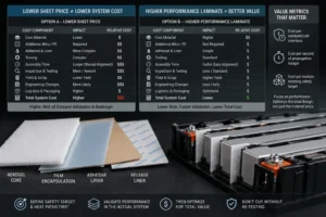
Compare Cost by Validated Function, Not Price per Square Meter
The lowest sheet price is not always the lowest system cost. A cheaper material may require additional mica, thicker PC, more complex adhesive, manual alignment, extra inspection, or repeated module testing. A higher-performance laminate may reduce thickness, part count, assembly time, or pack mass.
Compare total converted-part cost: core material, films, adhesive, liner, tooling, yield, die-cut cycle time, inspection, cleaning, packaging, scrap, logistics, and quality documentation. Include the cost of engineering changes and delayed validation.
Use a value metric linked to performance, such as cost per validated cell interface, cost per second of propagation margin, or cost per module meeting the acceptance criterion. These metrics encourage the team to optimize the full design instead of purchasing a material in isolation.
Design-to-cost should occur after the major heat paths and safety target are understood. Removing edge coverage, reducing thickness, or changing adhesive without repeat testing can create a false saving.
Industry Insight: Battery Aerogel Insulation for EVs Is Becoming Multifunctional
The market is moving away from fragile standalone aerogel felt toward reinforced, encapsulated, and multifunctional barriers. Current research combines aerogel with stronger fiber networks, radiation-blocking additives, flame-resistant facings, phase-change materials, pressure-management layers, and structural dielectric films.
This trend reflects the demands of modern EV packs. Higher integration, fast charging, large-format cells, and cell-to-pack architectures create less space for safety components while increasing the consequences of propagation. The barrier must remain thin, mechanically stable, electrically safe, clean, and compatible with automated assembly.
Recent research also shows why conservative engineering is necessary. Aerogel can strongly delay or suppress thermal propagation in many tested configurations, yet conventional aerogel alone may not reliably prevent propagation in every severe large-format module. Vent routing, metal heat paths, electrical connection, cell energy, and hybrid protection remain critical.
For buyers, the competitive advantage is no longer simply access to an aerogel roll. It is access to a supplier that can convert the material into a controlled, traceable, test-ready part and improve it quickly after prototype feedback.
RFQ Checklist for Battery Aerogel Insulation for EVs
Send the cell chemistry, cell format, capacity, dimensions, nominal and worst-case state of charge, vent location, expected vent direction, module layout, electrical connection, cooling method, available gap, target installed thickness, compression range, and end-of-life swelling allowance.
Define the performance target: required propagation delay, no-propagation observation period, protected-cell temperature limit, dielectric requirement, flame requirement, vent or flame exposure, and planned test method.
Provide a 2D PDF or CAD file with critical dimensions, tolerances, keep-out zones, adhesive areas, pull tabs, liner split, edge sealing, orientation, identification, cleanliness, packaging, and annual volume.
Request the supplier’s thermal, mechanical, electrical, flame, aging, chemical, adhesive, traceability, inspection, and change-control documentation. Agree on the prototype and validation plan before freezing tooling.
How Boost Insulation Supports Battery Aerogel Insulation for EVs
Boost Insulation supports EV and energy-storage projects with aerogel, flame-retardant polycarbonate, silicone foam, mica, dielectric films, pressure-sensitive adhesives, lamination, slitting, precision die cutting, and custom assembly.
Engineering support can include material screening, multilayer stack design, vent keep-out review, compression analysis, adhesive zoning, edge encapsulation, pull-tab and liner design, DFM, rapid prototypes, dimensional inspection, withstand-voltage testing, flame screening, aging tests, packaging, APQP, PPAP, and lot traceability.
For a productive review, upload the cell or module drawing and include the installed gap, compression range, vent direction, safety target, material restrictions, validation method, annual volume, and any current assembly or test failure. The objective is to recommend a manufacturable part for testing—not to make an unsupported pack-level guarantee.
| Need help selecting and converting an EV aerogel barrier?
Send Boost Insulation your cell or module drawing, installed gap, compression range, vent location, safety target, material restrictions, validation method, and expected annual volume. The engineering team can review aerogel, PC insulation, silicone foam, mica, films, adhesives, and precision die-cut options. Visit boostinsulation.com to upload a drawing or request a quote |
Frequently Asked Questions
What is the best aerogel thickness for EV battery cells?
There is no universal thickness. Select the minimum installed thickness that meets the module target with margin under worst-case compression, cell energy, state of charge, venting, and production tolerances.
Should aerogel be placed between every battery cell?
Prismatic and pouch modules often use a barrier at each interface, but cylindrical packs may use row, group, or module partitions. The correct layout follows the dominant propagation paths and must be validated.
Can aerogel also provide electrical insulation?
Some laminates can contribute dielectric isolation, but the exact finished construction must be tested. Do not assume every aerogel core or composite is electrically insulating.
Does UL94 V-0 prove that aerogel prevents thermal propagation?
No. UL94 V-0 is a small-scale material flammability classification at a specified thickness. It does not prove jet-flame resistance, propagation delay, or EV pack compliance.
Should battery aerogel use full-face adhesive?
Not automatically. Full-face adhesive can simplify assembly but may change thermal resistance, compression, and flame behavior. Selective adhesive is often evaluated to reduce thermal bridging.
Is aerogel better than mica between battery cells?
Aerogel usually offers higher thermal resistance in a thin, compliant layer. Mica offers rigid high-temperature electrical and flame protection. Many systems use aerogel between cells and mica near vents, covers, or direct flame zones.
Can silicone foam replace battery aerogel?
Silicone foam is valuable for gap filling, swelling, vibration, and preload management, but it generally performs a different function. Aerogel and silicone foam are often combined rather than treated as direct substitutes.
What information is needed for a custom die-cut sample?
Provide the drawing, cell format, installed thickness, compression range, vent location, adhesive pattern, encapsulation requirement, safety target, test plan, packaging, and expected annual volume.
Technical References
- United Nations Economic Commission for Europe. UN Regulation No. 100, Revision 3: electric power train and rechargeable energy storage system requirements. Source
- UL Solutions. Combustion (Fire) Tests for Plastics: UL 94 V, VTM, HB, and 5V classifications and test-method limitations. Source
- Liu, Q. et al. “Influence of Aerogel Felt with Different Thickness on Thermal Runaway Propagation of 18650 Lithium-ion Battery.” Electrochemistry, 2022. Source
- Wong, S. K. et al. “Mitigating Thermal Runaway Propagation in High Specific Energy Lithium-Ion Battery Modules Using Nanofiber Aerogel.” Energy, 2024. Source
- Hou, X. et al. “Thermal Insulation and Fireproof Aerogel Composites for Automotive Batteries.” Gels, 2025. Source
- Liu, Z. et al. “Achieving No-Propagation of Battery Thermal Runaway Using Advanced Thermal Barriers.” Applied Thermal Engineering, 2025. Source
- Boost Insulation. EV battery insulation, aerogel, flame-retardant polycarbonate, thermal management, die-cutting, and rapid-prototype capabilities. Source
Related Posts:
Why Choose a China Factory for Die-Cut Insulation?
How Does Aerogel Handle Cell Venting Heat in EV Packs?
How Does Flame Retardant Polycarbonate Compare to FR ABS Plastic?
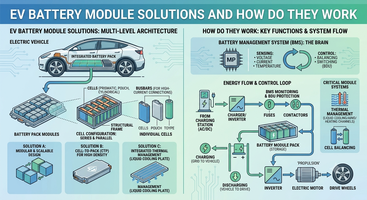
What Are EV Battery Module Solutions and How Do They Work?
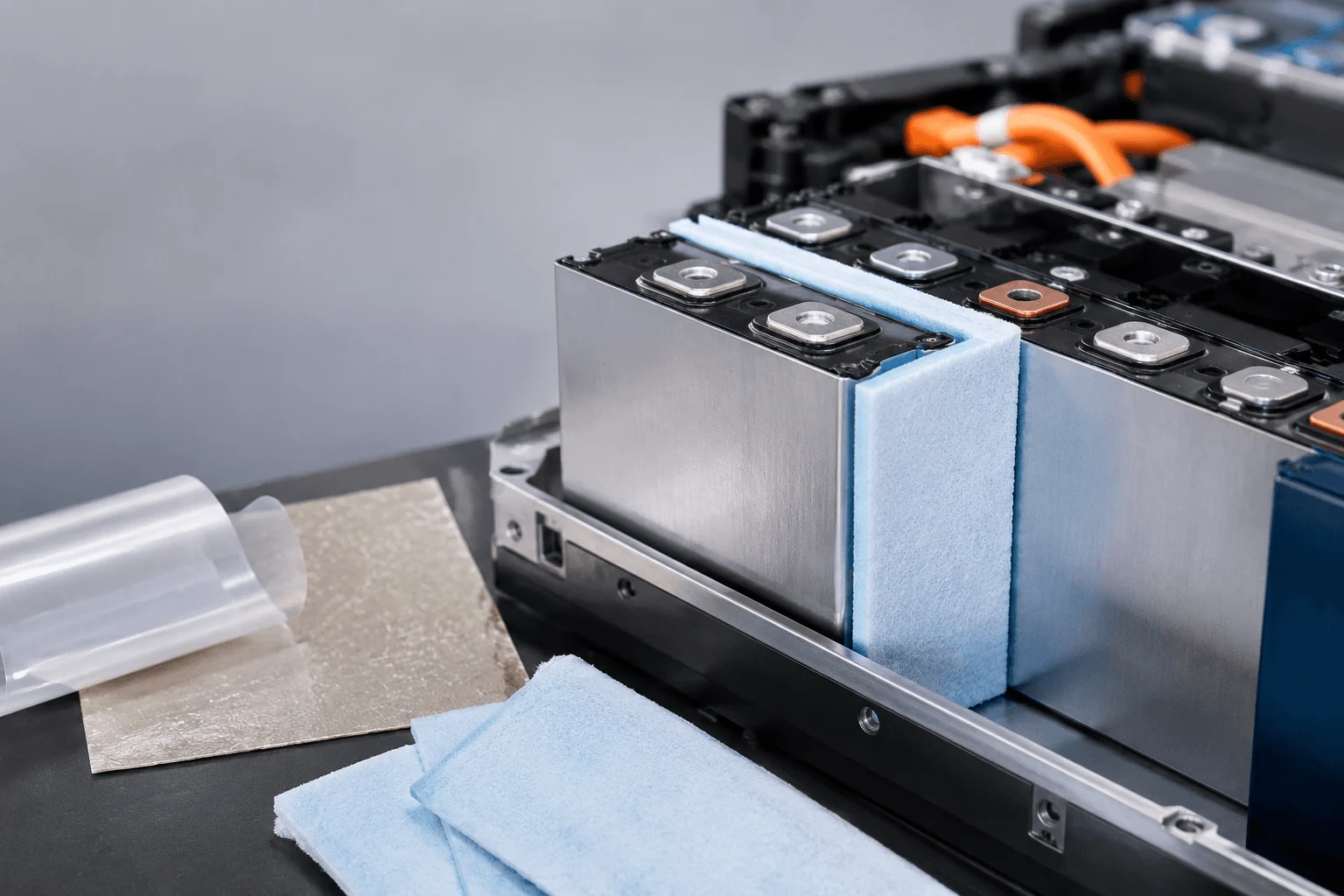
How Do You Select Aerogel Thickness Between Cells?
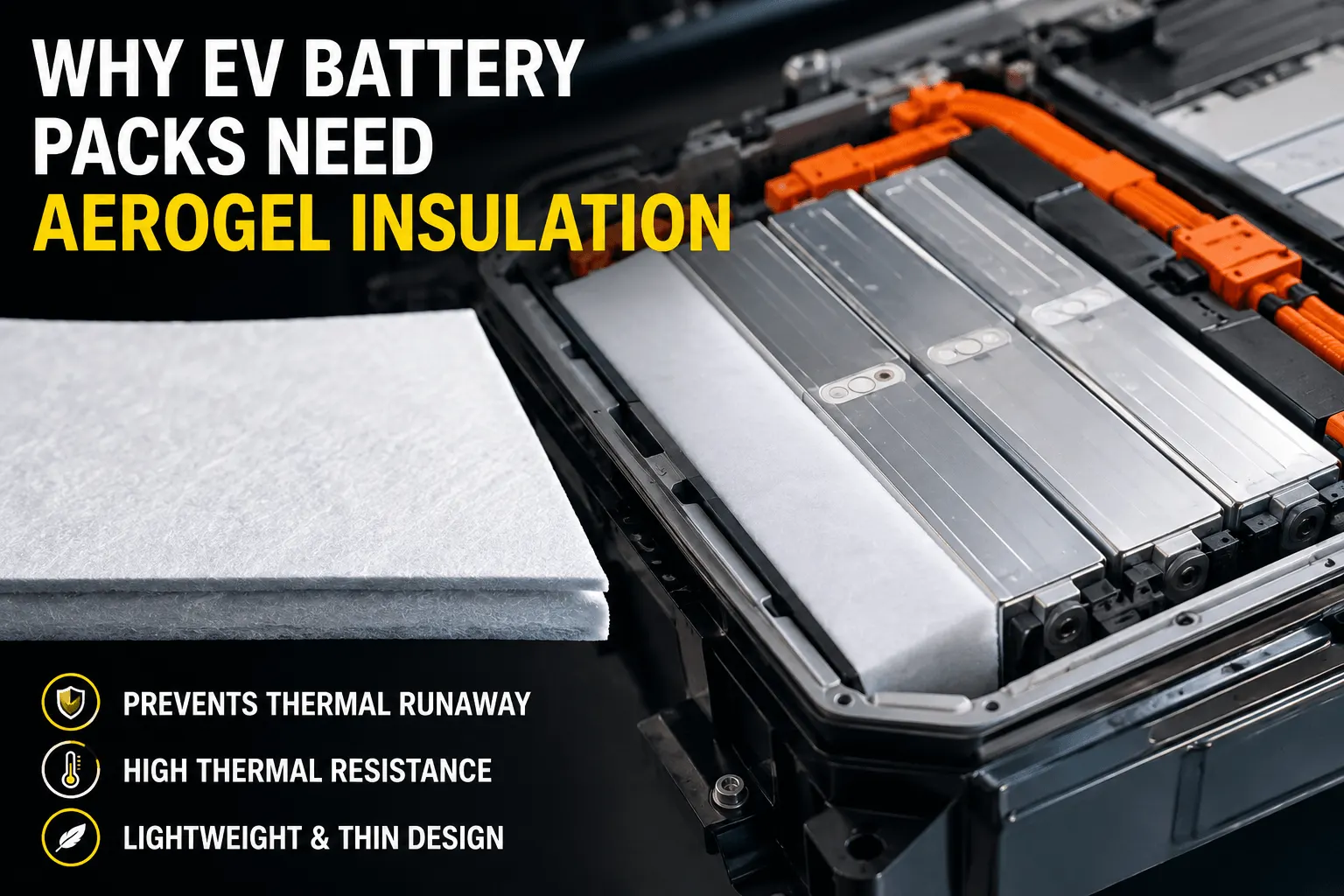
Why Do EV Battery Packs Need Aerogel Insulation Today?
 betty wong