
How Do You Test Bend Damage in Ceramic-Fiber Aerogel?
Table of Contents
An aerogel pad may fit a curved battery enclosure when first installed yet retain damage that is difficult to see. Temporary bending during handling, routing around a corner, or fitting a cutout can disturb a fragile composite even when ceramic fibers help support it. Cracks, loose particles, creases, and local thickness changes matter because the pad must protect a defined thermal path after assembly—not merely survive movement from one workstation to another. Engineers therefore need a controlled bend-damage test and an explicit way to decide whether the finished component remains acceptable.
To test bend damage in ceramic-fiber aerogel, identify the actual material grade and finished geometry, condition representative specimens, and record the undamaged condition. Bend specimens using a documented fixture with defined radius, angle, direction, loading rate, temperature, and cycle count. Afterward, examine both faces and the edges for cracks, splitting, distortion, and fiber or particle release; measure local thickness under a consistent measurement load. Compare results with unbent controls. Where the damage could affect thermal function, qualify the relevant thermal response separately. Acceptance criteria must follow the battery installation and its engineering requirements, not a universal advertised bend radius.
Why Does Bend Damage Matter in EV Battery Aerogel Pads?
Ceramic-fiber-reinforced aerogel may be specified as an intercell insulation layer, local partition, or shaped thermal shield. A flat material coupon is not necessarily the geometry delivered to an automotive assembly line. A converter may cut notches, slots, and narrow bridges; installers may temporarily curve the pad to clear tabs, fasteners, or a module wall. The test should reflect actual assembly or service loads.
Boost’s existing discussion of aerogel between battery cells addresses insulation selection; this article addresses what to inspect after the material has actually been bent.
What Happens Inside Ceramic-Fiber Aerogel During Bending?
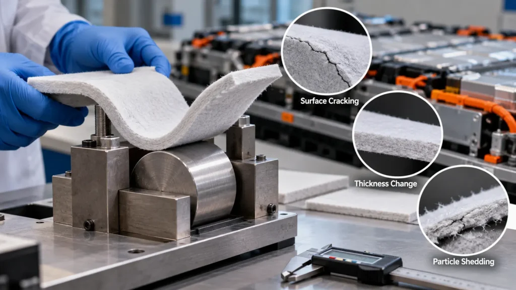
Many reinforced aerogel felts combine a porous insulating phase with a fibrous supporting network. The precise matrix, ceramic fiber composition, facing, and binder depend on the grade. During bending, the outer surface generally experiences extension while the inner surface experiences compression; local contact with a mandrel may add through-thickness compression and friction. A compressible felt does not necessarily behave like a uniform elastic sheet.
Candidate changes include cracks within the aerogel phase, disruption at fiber-to-matrix interfaces, local powder release, wrinkling or compression on the inner face, and tearing around an existing notch. These are potential mechanisms, not verified outcomes for every product. Fiber reinforcement may improve handling integrity without eliminating cracking. ### Which damage modes deserve separate records?
Table 1 — Bend Damage Mechanisms in Ceramic-Fiber Aerogel
| Potential Damage | Possible Cause | Inspection Method | Functional Concern |
| Surface cracking | Outer-face tensile deformation | Photographs under controlled lighting | Local continuity and subsequent handling |
| Internal composite damage | Fiber–aerogel interface movement | Agreed microscopy or other suitable examination | Damage not visible at the surface |
| Edge splitting | Bend near a cut or unsupported margin | Two-sided edge inspection | Coverage loss and loose fragments |
| Fiber or particle shedding | Matrix disruption or edge abrasion | Controlled collection and particle review | Cleanliness and material loss |
| Permanent crease or thinning | Inner-face compression or local restraint | Thickness and shape mapping | Reduced installed insulating path |
| Facing separation | Different bending response between layers | Interface inspection, where applicable | Changed positioning and durability |
How Should Engineers Define the Test Objective?
A meaningful protocol begins with an engineering decision, not with a machine setting. Material screening compares candidate grades under identical conditions. Manufacturing qualification examines cutting, packing, lifting, and installation. Finished-part validation tests the actual holes, edges, facings, and mounting constraints. Repeated-bend testing is appropriate only when repeated handling or service motion is credible. Each purpose calls for an appropriately representative specimen and a statement of what passing the test will—and will not—demonstrate.
How Should Bend-Test Specimens Be Prepared?
Record supplier, controlled grade designation, lot, thickness, construction, and any reinforcement direction that is documented. Mark the side facing the inner curvature, note whether a coating or protective film is present, and photograph initial surfaces and edges. Use defined specimen dimensions, cutting procedures, conditioning environments, handling methods, and inspection lighting. Establish unbent controls from the same material lot where feasible. If the objective concerns a laminated part, do not remove its adhesive or facing simply to make the test easier.
How Do You Select Bend Radius, Angle, and Direction?
Define which radius is meant. Mandrel diameter is twice its mandrel radius; neither should automatically be called the centerline radius of the specimen. A felt of finite thickness also has an inner curvature and an outer curvature. Local compression, springback, facing stiffness, friction, and fixture geometry complicate the relationship. Draw or photograph the fixture and indicate the measurement reference on the test sheet. Where a radius-to-thickness ratio is reported, treat it as a descriptive geometric variable—not an unverified safety threshold.
The angle, contact length, clamp positions, bending direction, loading speed, dwell time, and release procedure also need definition. If reinforcement orientation or surface facings create directional behavior, test the relevant orientation rather than assuming symmetry. A controlled bend around a battery corner should reproduce the actual constrained path, not just the easiest path for a flexible strip.
There is no universal safe minimum bend radius for ceramic-fiber aerogel. Any candidate radius requires material-grade, thickness, construction, and application-specific evidence.
Table 2 — Bend-Test Setup and Documentation
| Test Variable | Required Definition | Engineering Importance | Reported Evidence |
| Grade and thickness | Controlled grade, actual thickness, lot | Composite responses vary | Identification and measurement record |
| Fixture geometry | Mandrel dimensions, supports, restraints | Changes actual curvature and contact | Drawing or calibrated photograph |
| Bend direction and angle | Face orientation and angular travel | Changes local tensile zone | Orientation mark and setting |
| Loading history | Rate, cycles, dwell, release | Distinguishes installation and fatigue effects | Equipment log or operator record |
| Environment | Conditioning and test temperature | Can change response | Environmental log |
| Inspection timing | Immediate and specified post-bend checks | Damage and relaxation may evolve | Timestamped observations |
Does single-bend testing differ from repeated bending?
Yes. One-time installation testing should reproduce the worst credible bend needed to position the part, including temporary handling restraints. Repeated bending tests ask whether defined recurring motion produces progressive cracking, shedding, or shape changes. A cycle must specify its angular endpoints, radius, rate, and any dwell. Evaluate both directions when the product can be reversed during installation; evaluate one direction when production fixtures prevent reversal.
Table 3 — Selecting the Representative Bend Scenario
| Test Scenario | Representative Loading | Main Inspection Target | Qualification Limitation |
| Single installation bend | One specified path into fixture | Initial cracks and local creases | Does not establish fatigue life |
| Repeated handling | Defined load–unload sequence | Progressive debris and edge splits | Does not recreate vehicle loads by itself |
| Aged-material bend | Bend after prescribed conditioning | Sensitivity to condition changes | Not a thermal-runaway test |
| Installed part | Production shape under actual restraints | Coverage, interface fit, localized damage | Requires separate system-function evidence |
How Should Temperature and Conditioning Be Controlled?
Define storage before the test, initial temperature, humidity if material-relevant, thermal history, and when the specimen is inspected. Testing as-delivered room-temperature material, bending after an aging treatment, and bending while hot answer distinct questions. Exposure to elevated temperature can also affect facings or adhesives differently from the aerogel core; the scope of any comparison must name the complete construction.
How Do You Inspect Surface Cracks and Edge Damage?
Photograph the part before testing with a consistent background and scale. After bending, inspect the outer and inner surfaces, side edges, inside corners, slots, narrow bridges, and adhesive or facing boundaries. Standardize lighting, inspection distance, magnification where relevant, and the orientation of photographs. Record location and extent rather than simply checking a box labeled “damage.” Where justified, use optical magnification or a validated nondestructive technique to investigate damage that surface inspection cannot resolve.
A crack indication by itself does not quantify lost thermal resistance. Nor does the absence of a visible crack prove there is no internal disturbance. The acceptance document should connect a specified observation to a function or explicitly require additional evidence. For critical damage, preserve the specimen to permit review against an unbent control and a production drawing.
How Do You Evaluate Fiber and Particle Shedding?
Particle and fiber shedding merit a separate controlled assessment because a part can look continuous yet release debris during bending or unpacking. The test may use a clean collection surface, controlled handling, a documented collection step, selected microscopy, or a mass difference when appropriate. Define the background contamination level and prevent material losses during transfer. Record whether debris originated at the original cut edge, a newly cracked surface, or an adhesive interface.
Mass change alone does not describe particle number, size, composition, or electrical implications. A wiping procedure without consistent pressure and stroke count is difficult to compare.
Industry Insight 1 — A flexible sample can still fail a cleanliness requirement. Engineering teams sometimes focus on cracks because they are easy to photograph. A verified shedding protocol can reveal a different kind of assembly risk: contamination during insertion or handling. The action is to specify particle collection and inspection separately from mechanical pass/fail.
How Should Post-Bend Thickness and Shape Be Measured?
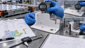
Thickness is central to the installed thermal path, but soft felt can produce different readings under different probe forces. Record the instrument, contact area, measurement load, conditioning, and marked positions. Compare the same positions before and after bending where practical, including creases, inside corners, narrow strips, and locations near holes. A local decrease may matter more than the average thickness across an undamaged area.
Distinguish free-state thickness from thickness under the actual assembly compression. After a component is straightened for measurement, flattening can alter its contact state; report that procedure explicitly. For a mounted curved part, evaluate actual installed clearances and coverage where measurement access permits. Do not assign a pass percentage without an accepted drawing or functional basis.
Table 4 — Post-Bend Inspection and Measurement
| Inspection Item | Possible Finding | Measurement Approach | Acceptance Basis |
| Outer and inner faces | Crack, crease, surface change | Controlled images and defect map | Project-defined location and severity |
| Cut edges and notches | Split, loose fiber, fragment | Edge microscopy or visual inspection | Drawing and cleanliness requirements |
| Local thickness | Thinning or irregular depression | Defined-contact-force thickness map | Installed gap and thermal function |
| Shape and fit | Permanent curl or loss of coverage | Overlay, fixture, or dimensional check | Assembly tolerance and retention |
| Particle release | Collected fibers or dust | Defined collection and characterization | Application cleanliness limit |
| Laminate interfaces | Peeling or local separation | Interface inspection if applicable | Validated construction acceptance |
Industry Insight 2 — Measurement pressure can hide a thickness problem. A heavily loaded gauge may compress both good and damaged zones toward similar values, while inconsistent operator contact creates artificial variation. A controlled measurement definition makes the post-bend comparison meaningful for design and supplier quality.
Can Bending Change Thermal Insulation Performance?
Potentially, but the mechanism and magnitude must be demonstrated. A crack can affect local contact, coverage, or continuous insulation thickness; an installed gap can establish a bypass path. An apparent surface line may also have little measurable consequence in a specific configuration. Aerogel’s reported conductivity as an undamaged flat material does not resolve either question.
Thermal conductivity describes a material result under defined conditions, while an installed barrier adds shape, compression, seams, supports, facings, and adjacent conductive structures. Keep those distinct when interpreting damage. Boost’s existing thermal-conductivity guide addresses material and installed thermal resistance; this bend-specific assessment asks whether the geometry or material condition changed enough to require fresh evidence.
How Should Thermal Performance Be Re-Tested After Bending?
First, identify the actual requirement. If the decision concerns comparable flat material, choose a suitable test method and compare damaged and unbent controls of the same grade, construction, conditioning, thickness state, and measurement direction. ASTM C518 measures steady-state thermal transmission using a heat flow meter with flat slab specimens; ISO 8301 addresses steady-state thermal resistance and related properties using a heat flow meter for flat specimens. Neither is a universal test of the heat-transfer performance of an installed curved component. The specimen and method must satisfy their applicability conditions.
A curved, permanently creased, or fragmented specimen may not fit a flat-plate apparatus without being changed by the preparation itself. Flattening such a specimen can mask the geometry responsible for heat leakage. If the critical concern is the actual fitted corner, plan a representative component-level arrangement measuring relevant hot-side, protected-side, or heat-flow response under agreed conditions. Report contact pressure, orientation, fixture losses, source temperature or heat flux, exposure duration, and any uncertainty relevant to the comparison.
Do not treat a room-temperature conductivity test as proof of thermal-runaway performance. The latter requires a separate, representative validation plan addressing high heat, transient exposure, adjacent materials, and routes around the part. Existing Boost discussion of grade verification provides broader supplier context; this article concerns the evidence needed specifically after bending.
Table 5 — Thermal Function Evidence After Bend Exposure
| Test Level | What It Can Show | Important Controls | What It Cannot Prove |
| Flat material coupon | Comparative steady-state resistance | Thickness, mean temperature, compression | Installed curved-joint behavior |
| Damaged material coupon | Condition change when method remains suitable | Control lot, sample preparation, repeatability | Thermal-runaway protection by itself |
| Curved component fixture | Heat path and gaps in representative geometry | Contact, facing, restraints, heat source | Full pack response |
| Module / pack validation | Behavior in specified assembly and abuse scenario | Cells, vents, SOC, interfaces, instrumentation | Universal performance in every battery |
Industry Insight 3 — Appearance cannot stand in for thermal evidence. A defect should trigger a defined investigation rather than an automatic, unsupported claim of conductivity loss. Match the test level to the affected heat path; where curvature and edge gaps control performance, coupon data is not enough.
How Do Cutouts, Narrow Sections, and Facings Change the Result?
A die-cut slot interrupts the supporting fiber network and may place a corner in the highest bending region. Narrow bridges can fold differently from a broad sheet, particularly when a machine grip or operator touches them. Map the bending path onto the part drawing and identify notches, holes, sharp internal corners, and unsupported perimeter strips. The flat sample that passes material screening may still be inappropriate for a finished component with these features.
Adhesive and carrier layers also matter. A facing may distribute strain or restrict movement; adhesive can locally constrain curvature and introduce a peel interface. A laminated construction should therefore be tested as delivered when the qualification concerns the finished part. For broader context, Boost’s aerogel-grade selection article describes material selection factors distinct from damage testing.
Industry Insight 4 — The finished drawing is a test variable. Move from an ideal strip to an actual die-cut profile before production release. The implications are practical: critical cutouts may require a different bend path, fixture design, or protective packaging even when the base material grade has not changed.
How Should an Installed Aerogel Pad Be Evaluated?
Set the finished pad into a representative housing or module fixture using the intended orientation, mating surfaces, restraint, and assembly sequence. Check for incomplete coverage, lifted edges, excessive contact compression, new cracks, loose material, and the possibility that neighboring hardware abrades the barrier. Record what can and cannot be accessed for inspection. ## How Do You Establish Defensible Bend-Damage Acceptance Criteria?
Use the chain application requirement → controlled loading → measured attribute → acceptance rule → supporting evidence. Define which cracks, edge splits, particles, local thickness changes, and shape deviations are important, and why. If a cosmetic observation does not change assembly or protection, the team may choose an approved visual limit. If a defect might interrupt barrier coverage or contaminate a sensitive region, require measurement or further validation. A verified failure is different from a plausible concern.
Acceptance thresholds must come from the actual design, test repeatability, material grade, and validated functional relationship. There is no universal acceptable crack length, shedding count, bend radius, or percentage of retained thickness.
Industry Insight 5 — Pass/fail language must be linked to measurable evidence. A supplier instruction that says “no damage” is often too vague for repeatable production release. Define the observation technique and actual acceptance boundary; otherwise, two inspectors can reach different decisions about the same pad.
Example: Qualifying an Aerogel Pad Around a Battery Corner
Hypothetical engineering example; no customer test results are implied. A battery design uses a custom ceramic-fiber aerogel pad with a clearance slot and a curved installation region. The engineering team supplies the material-grade reference, controlled component drawing, target installation sequence, mating geometry, handling restrictions, and required thermal barrier function. A test engineer prepares unbent controls and production-shaped prototypes from identifiable material lots.
The prototypes are bent around a documented fixture representative of the intended assembly and inspected before, immediately after, and at the specified post-test interval. Images record both faces and the slot corner. The team checks the cut edge for debris, maps local thickness, and confirms fit and thermal-barrier coverage in a matching assembly fixture. If observed damage could affect function, thermal testing is selected at a suitable specimen or component level. The engineering decision is qualified, not qualified, or additional evidence required—based on the customer-approved criteria, not a fabricated universal radius or defect limit.
What Should a Supplier Bend-Test Report Include?
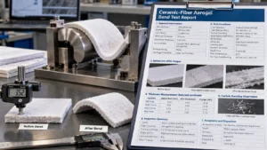
A practical report identifies the material manufacturer and grade, batch or lot, nominal and measured thickness, construction, specimen shape, surface facing, cut-edge condition, and pre-test conditioning. It describes test objective, written method and revision, fixture geometry, definition of bend radius, angle, direction, rate, number of cycles, dwell or recovery interval, and temperature. It includes before-and-after images, inspection locations, local thickness measurements, shedding observations, any post-bend functional testing, deviations, acceptance limits, and engineering disposition.
These are recommended customer–supplier reporting fields, not claims that a single published standard requires all of them. If a method has been adapted from an existing fabric-stiffness or plastics-flexure test, disclose exactly what changed. ASTM D1388 measures stiffness properties of fabrics; ASTM D790 covers flexural properties of plastics and insulating materials in specified bar geometries. Neither may be invoked automatically as a certification of bend-damage resistance for a compressible ceramic-fiber aerogel felt.
Table 6 — Supplier Evidence and RFQ Matrix
| Requirement | Customer Input | Supplier Evidence | Acceptance Question |
| Approved material | Grade, thickness, facing | Datasheet and lot identity | Is construction traceable? |
| Finished geometry | Drawing and bend path | Prototype profile and inspection | Are critical cutouts represented? |
| Bend protocol | Fixture, direction, cycles | Method revision and load record | Was deformation representative? |
| Damage inspection | Crack, edge, particle targets | Photos, measurements, collection | Are findings within agreed criteria? |
| Thermal function | Protected region and requirement | Appropriate test report if needed | Does evidence address the actual heat path? |
| Release control | Approval and change requirements | Signed disposition and revision | Can future lots be compared? |
Industry Insight 6 — A supplier report should support a decision, not only display photographs. Make the link between the grade, exact component revision, mechanical exposure, measured outcomes, and approved limits explicit. This provides a baseline if the fiber carrier, facing, cutting route, or packaging later changes.
Common Mistakes When Testing Aerogel Bend Damage
The following mistakes frequently reduce interpretability; each has an engineering control rather than a one-size-fits-all solution.
- Calling material “flexible” without conditions: define curvature and handling history so claims can be compared.
- Omitting grade identification: link every sample to the approved composite construction.
- Ignoring thickness: record measured thickness because bending strain and fixture contact depend on geometry.
- Confusing mandrel diameter and bend radius: mark the radius reference directly on the fixture drawing.
- Omitting bend direction: mark the face and relevant material orientation before testing.
- Ignoring fixture restraint: document clamp and contact conditions so local compression is understood.
- Changing conditioning between specimens: stabilize and log comparable states before interpreting differences.
- Selecting arbitrary cycles: match the count and motion to the expected handling or service history.
- Testing raw sheet only: add production-shaped prototypes when notches and edges matter.
- Ignoring narrow bridges: examine the actual regions where strain concentrates.
- Inspecting only the outer face: include the inner face, edges, and exposed laminate interfaces.
- Ignoring particle release: collect and characterize debris using an agreed procedure.
- Measuring thickness with inconsistent pressure: define instrument contact conditions and positions.
- Assuming no visible crack means no damage: qualify hidden or functional concerns when relevant.
- Using one bend test to claim pack safety: keep component integrity separate from system thermal validation.
Engineering Checklist for Ceramic-Fiber Aerogel Bend Testing
Use this checklist to prepare a controlled test plan and supplier review, not as a substitute for application-specific acceptance limits.
- Application and traceability: battery location, protected surface, supplier, approved grade and revision, material lot, component drawing, specimen identification.
- Construction and dimensions: reinforcement description when supplied, nominal and measured thickness, dimensions, critical cutouts, edge quality, facing, adhesive, orientation.
- Conditioning and fixture: pre-test environment, temperature history, mandrel dimensions, defined bend radius, angle, direction, speed, clamps, contact surfaces.
- Load history: one-time versus repeated bending, cycles, dwell, release and inspection timing, any pre-aging treatment.
- Evidence capture: before-and-after images, crack and edge maps, fiber and particle collection, local thickness under defined measurement load, shape and fit checks.
- Functional review: need for thermal re-test, suitable method, control specimens, actual component or installed fixture, customer-specific acceptance criteria.
- Release controls: report, uncertainty or limitations, departures from procedure, disposition, engineering approval and supplier-change triggers.
RFQ Checklist for Custom Ceramic-Fiber Aerogel Pads
Send an application description and a PDF drawing with DXF or DWG profiles when available. Include a 3D assembly model where curvature is difficult to show in two dimensions. Identify the expected installation path, available space, nominal thickness, candidate material grade, bend direction, sensitive cutouts, narrow sections, facing or adhesive requirements, and handling method. Specify the required thermal function, cleanliness conditions, bend-test objective, proposed acceptance criteria, prototype quantity, planned annual demand, and documentation requirements. If the bend radius is not defined, provide actual assembly geometry so a proposed fixture can be evaluated rather than requesting an unsupported universal minimum radius.
How Boost Insulation Supports Custom Aerogel Components
Boost Insulation’s published content describes battery aerogel material options and conversion considerations in applications where thickness, coverage, films, and cut geometry matter. Any offered die-cutting, facing, lamination, inspection, or test documentation should be confirmed for the actual grade and quotation scope.
Material procurement and precision converting are not equivalent to independently certified bend testing or battery-pack thermal propagation validation. The material manufacturer, component supplier, specialized laboratory if used, and OEM engineering team should agree which party provides each evidence package. For a custom design, an early material and manufacturability review can reduce sample iterations without replacing customer qualification.
Frequently Asked Questions
1. How do you test bend damage in ceramic-fiber aerogel?
Condition and identify representative material or finished-pad specimens, document their initial thickness and visible condition, then bend them using a fixture with defined radius, angle, orientation, speed, and loading history. Inspect the inner and outer faces and cut edges after release. Record cracking, splitting, particle release, creasing, dimensional changes, and any interface damage. Compare with unbent controls, and request thermal or installed-component verification when the findings could affect the required barrier function.
2. Can ceramic-fiber aerogel crack when bent?
Yes, a reinforced aerogel composite may develop local cracks or other damage when its grade, thickness, construction, or imposed geometry exceeds its demonstrated handling capability. Fiber reinforcement supports the composite but does not eliminate the possibility of disruption in the insulating phase or at cutouts. Whether a particular crack is unacceptable depends on its location, extent, material architecture, and actual application requirement. A controlled assessment is preferable to assumptions.
3. What bend radius is safe for ceramic-fiber aerogel felt?
There is no universal safe bend radius for all ceramic-fiber aerogel felts. The acceptable value depends on grade, thickness, fiber construction, surface facing, bend direction, fixture contact, and whether the part is bent once or repeatedly. Define the radius reference clearly, then evaluate representative finished components across the installation geometry. The resulting approved condition should be documented as specific to the tested part and application, not applied automatically to different grades or thicknesses.
4. Does ceramic-fiber reinforcement prevent aerogel cracking?
Not necessarily. A reinforcing fiber network may improve handling and help hold the composite together, but actual behavior depends on the grade, pore structure, fiber arrangement, binder or surface construction, and deformation conditions. Reinforcement can coexist with microcracking, dust release, or permanent creasing. Engineers should establish which changes occur under the planned bend exposure and whether they affect the part’s thermal, dimensional, or cleanliness requirements. A statement of reinforcement alone is not a qualification result.
5. How do engineers inspect aerogel after bending?
Start with repeatable before-and-after photographs of both bend surfaces, the perimeter, notches, and other critical features. Examine cracks, edge splits, creases, local shape changes, and any separation at facings or adhesive interfaces. Measure thickness with a defined probe force and record the locations. If particle shedding or hidden damage matters, use a suitable documented collection or inspection method. Link every observation to a specimen identifier and the drawing’s agreed acceptance criteria.
6. Can bending cause ceramic-fiber aerogel to shed particles?
It can, depending on the composite grade and the local deformation, especially where the insulating matrix or cut edges are disrupted. A controlled test should distinguish fiber release, loose aerogel dust, handling contamination, and debris already present before loading. Mass loss may support comparison but cannot determine particle size or composition by itself. Electrical or assembly cleanliness requirements should drive the collection method and acceptance limits; occupational exposure considerations require separate appropriate assessment.
7. Does bending change the thermal performance of aerogel insulation?
Bending may change thickness, create gaps, disturb interfaces, or cause cracking that warrants thermal evaluation, but a measurable conductivity change should not be assumed without testing. A superficial crack is not automatically a demonstrated thermal failure, and an intact-looking surface is not proof of unchanged performance. Use comparable controls and an applicable method when measuring material thermal properties. For curved or constrained parts, evaluate the actual barrier geometry and relevant heat path separately.
8. Should engineers test flat aerogel sheets or finished battery pads?
Both can be useful for different decisions. Flat specimens help compare material grades under consistent conditions, while finished die-cut pads reproduce holes, slots, narrow bridges, adhesives, surface facings, and actual edge conditions. If assembly curvature or restraint drives the risk, test the installed geometry as well. A passing material coupon cannot automatically qualify the converted component or battery module. The test plan should identify which evidence supports each approval step and which remains outstanding.
Request a DFM Review for Custom Ceramic-Fiber Aerogel Pads
If you are developing an aerogel barrier for an EV battery, share your material-grade information, PDF/DXF/DWG drawing, installed curvature or 3D assembly, critical cutouts, thickness, facings, handling sequence, expected bend exposure, cleanliness requirements, thermal validation targets, and desired prototype volume. Boost Insulation can discuss available material and component options and clarify the required manufacturing evidence for your project. Send aerogel drawing + bend geometry + acceptance requirements → material/DFM review → prototype request.
Related Posts:
How Does Silicone Foam Work With Aerogel Barriers?

Which Aerogel Grade Is Best for High-Voltage EV Cells?

Why Choose a China Factory for Die-Cut Insulation?

Where Is Aerogel Used Inside Modern EV Battery Packs?
What Makes Flame Retardant Polycarbonate Ideal For Batteries?

How Can Buyers Verify Aerogel Grades for EV Battery Use?
 root
